Impact of Engine Layouts on Aircraft Characteristics

ThePolishAviator

ACCESS: Restricted
Joined
29 January 2021
Messages
6
Reaction score
6
The A-engine configuration surly didn't help looking backwards and also not in looking along the symmetry axis forward. The improvement was in looking slightly downwards and sideways in frontal direction.

Here you find an intresting video on how bullet prooved glas can even enhance the vision:

View: https://www.youtube.com/watch?v=uCGsyjt5ANU&ab_channel=I%2FJG27_Nemesis
1719867525837.png
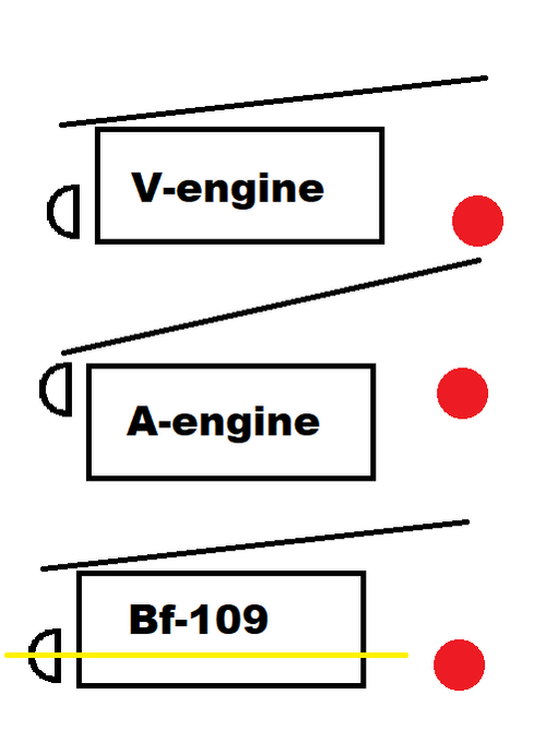
I have made a very professional paint diagram of what I meant.

The red dot is the aircraft center of gravity, the half-circle is the propeller, the sloped line represents the pilots vision and the yellow line is the Bf-109s cannon.

Because the luftwaffe wanted the cannon to fire through the propeller spinner instead of being synchronized and since the propeller has to be in line with the CG the designers had to sacrifice the potential vision benefit of the A-engine by mounting it much higher and running the cannon between the cylinders.

And when it comes to the advantage in looking at the slightly downwards, sideways direction that is not the case in the Bf-109 either. The designers chose to mount guns in the cowling making the Me-109 about the same when it comes to visibility as it's peers (if not putting it behind due to the struts holding canopy glass together.
 
I think we shold make a seperate thread about it, we're getting very off topic...
 
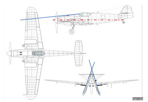
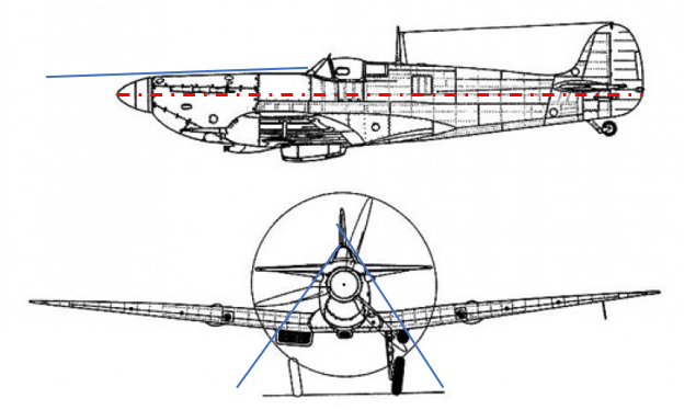
It is a nice drawing, but from looking at true drawings of the Me109 and Spitfire I would say, it’s not the case. Please not the blue “downward angle” that I’ve drawn (Me 109: 6°; Spitfire 2°) and the inclination of the “looking down angle to the side” (Me 70°; Spit 55°).

Also note, that the exhaust flames disturbed night vision in the Spitfire significantly.

1719936387839.png 1719936420931.png
 
Last edited:
If we look at the evolution of automobile engines and airplane engines, we will see that the inverted V engines made by MB and Junkers were the odd-ones-out.

Automobile engines started with their crankshafts on the bottom because that provides the shortest route to the drive axle. Later automobile engines just added cylinders until they reached 8-cylinder, straight, in-lines.
The next step was adding a second bank of cylinders to make upright V-engines (see the Rolls-Royce Merlin upright, V-12 engine installed in Spitfire). Spitfire engine cowlings are widest at the top, which interferes with vision.

A parallel development was the upright V engines designed by Hispano-Suiza (license-built by Klimov in the USSR) that were still upright Vs. but added auto-cannons nestled between the two banks of cylinders. HS needed the propeller speed reduction unit to raise the thrust line above the crankcase and allow the cannon to fire through the hollow propeller shaft.
HS built their first motor-cannons during World War 1 and installed them on a few SPAD fighters. During WW2, HS motor-cannons were installed on a few French fighters (e.g. Moraine-Saulnier) and most of the Yakovlev fighters.
Installing a motor-cannon interfers with all the intake plumbing in the valley between the Vs, so was only done by a few engine manufacturers (Hispano-Suiza and Klimov).

Germany was the odd-man-out with the inverted V engines built by Mercedes-Benz and Junkers. Inverted V engines start with a high-mounted crankshaft, but negate that by installing a PSRU that lowers the thrust line allowing a motor-cannon to be installed in the "valley" between the cylinder banks, but BELOW the crankshaft. Mounting the thrust line below the crankshaft forces landing gear legs to be longer. Inverted V engines only have an advantage in slant visibility along the sides of the nose. An extreme example is the triangular fuselage of the Me.262 jet.

An obscure example is the inverted V air-cooled engines built by Ranger during the 1940s. When Ranger installed a 520 horsepower, V-770, inverted V-12 engine in the Bell XP-77 light fighter, they installed a PSRU that RAISED the thrust line above the crankcase and allowed installation of a 20mm auto-cannon ABOVE the crankcase. This high thrust line allowed for short landing gear and a triangular engine cowling for better visibility alongside the nose.
 
There is not one perfect solution for all applications, e.g. radial engines were highly sucssessfull as aircraft engines, but not in the automotive or marine enviroment.

Inverted aero engines were not uncommon before WW2, the Menasco engines were also inverted and I believe there is still a decentdant of them in production in the Czech Republic.
 
I would say it does match the pilots point of view, please take a look on the first posting of this thread.
 
The amount of refraction is very angular and glass thickness sensitive so the 109 is a very different to the 190. Therefore you can’t assume the same viewing angle applies to both. Also steep angle come with other real world drawbacks such as sunlight glint and ghosting. There’s an informative explanation of this in an Avro Arrow documentary where they show the effects of different angles and thickness’s.
 
Hi,

View attachment 733418
I have made a very professional paint diagram of what I meant.

It's a good illustrative diagram, but the relative location of the propeller to the crankcase is more appropriate for early direct-drive engines, while the WW2-era fighter engines had a reduction gear in front of the crankshaft that displaced the propeller shaft towards the longitudinal axis of engine, in upright and inverted engines alike. I believe that was actually a requirement for the installation of an engine cannon, as the cannon couldn't fire through the crankshaft, as it would have to do on a direct-drive engine, but it could be made to fire through the displaced propeller hub which had a centreline running between the cylinder banks.

The German preference for inverted engines seems to go back at least to the 1921 textbook by H. Dechamps and K. Kutzbach, "Prüfung, Wertung und Weiterentwicklung von Flugmotoren", where it was suggested as a future design objective. So when the RLM specified an inverted layout for military engines in the 1930s, they were not actually coming up with something new at all ... :)

Regards,

Henning (HoHun)
 
Note that the pilot sits quite close to the windscreen. Something unlikely to be maintained for more than a minute. Even less likely during manoevring.
 
I respectfully disagree. Moving from an upright posture to a reclining posture lowers the head.
 
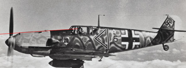
he is bent forward, so in an upright position, his eyes would be definately higher. Please feel free to find a better picture...
 
Last edited:
Hi Arjen,

Note that the pilot sits quite close to the windscreen. Something unlikely to be maintained for more than a minute. Even less likely during manoevring.

I find it really difficult to assess cockpit visibility from pictures alone.

Here's a page from a US manual that shows forward visiblity of different US fighters:


It would be quite interesting to see similar graphs for more aircraft types, of course.

Note that there might actually be a difference between the shooting view and the "search view", in which the pilot's eye doesn't need to be aligned with the sightline of the gunsight.

Regards,

Henning (HoHun)
 
I find it really difficult to assess cockpit visibility from pictures alone.
So do I.
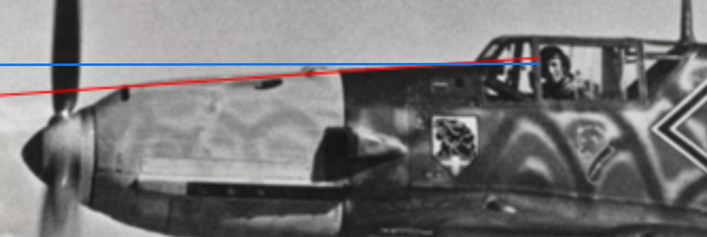
I noticed the red line ended at the pilot's hairline (the edge of his flying cap, to be precise), so I added a blue line that runs from the pilot's eyes through the lower edge of the windscreen. Make of it what you will.
Line of sight.png
 
Hi Arjen,

So do I.
I noticed the red line ended at the pilot's hairline (the edge of his flying cap, to be precise), so I added a blue line that runs from the pilot's eyes through the lower edge of the windscreen. Make of it what you will.
View attachment 733896

For the sighting view, you can use the gunsight - which in the photograph is visible as a box protuding into the cockpit below the windscreen - as a clue. However, it would probably be better to use a technical drawing for this, as relying on a single photograph isn't very accurate due to perspective and distortion issues, and photogrammetry requires multiple (somewhat) coordinated pictures (and is fairly complicated to begin with).

For the Me 262, I've seen drawings in which the lower limit of the sightline was explicitely indicated, but I haven't seen anything like that for the Me 109. In the Me 262 drawing, the difference between an armour glass windscreen and a non-armoured perspex windscreen was one degree extra depression for the sightline, if I remember correctly, but of course the Me 262's windscreen is flatter than the Me 109's, so the effect wouldn't be as pronounced there. (But still present, so one couldn't simply draw a straight line through the technical drawing and get accurate results.)

Here's a thread in a German forum demonstrating how the effect or the armour glass can be calculated if the relevant geometric dimensions are known:


Regards,

Henning (HoHun)
 

Similar threads

Please donate to support the forum.

Back
Top Bottom