Impact of Engine Layouts on Aircraft Characteristics

ThePolishAviator

ACCESS: Restricted
Joined
29 January 2021
Messages
17
Reaction score
16
The A-engine configuration surly didn't help looking backwards and also not in looking along the symmetry axis forward. The improvement was in looking slightly downwards and sideways in frontal direction.

Here you find an intresting video on how bullet prooved glas can even enhance the vision:

View: https://www.youtube.com/watch?v=uCGsyjt5ANU&ab_channel=I%2FJG27_Nemesis
1719867525837.png
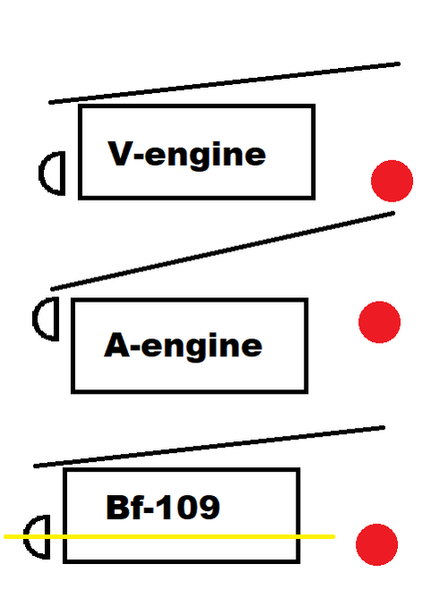
I have made a very professional paint diagram of what I meant.

The red dot is the aircraft center of gravity, the half-circle is the propeller, the sloped line represents the pilots vision and the yellow line is the Bf-109s cannon.

Because the luftwaffe wanted the cannon to fire through the propeller spinner instead of being synchronized and since the propeller has to be in line with the CG the designers had to sacrifice the potential vision benefit of the A-engine by mounting it much higher and running the cannon between the cylinders.

And when it comes to the advantage in looking at the slightly downwards, sideways direction that is not the case in the Bf-109 either. The designers chose to mount guns in the cowling making the Me-109 about the same when it comes to visibility as it's peers (if not putting it behind due to the struts holding canopy glass together.
 
I think we shold make a seperate thread about it, we're getting very off topic...
 
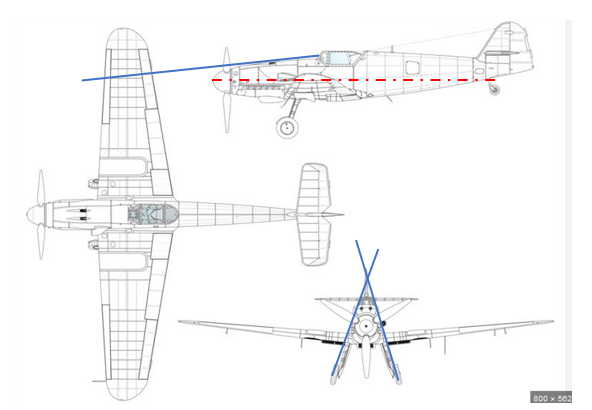
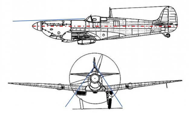
It is a nice drawing, but from looking at true drawings of the Me109 and Spitfire I would say, it’s not the case. Please not the blue “downward angle” that I’ve drawn (Me 109: 6°; Spitfire 2°) and the inclination of the “looking down angle to the side” (Me 70°; Spit 55°).

Also note, that the exhaust flames disturbed night vision in the Spitfire significantly.

1719936387839.png 1719936420931.png
 
Last edited:
If we look at the evolution of automobile engines and airplane engines, we will see that the inverted V engines made by MB and Junkers were the odd-ones-out.

Automobile engines started with their crankshafts on the bottom because that provides the shortest route to the drive axle. Later automobile engines just added cylinders until they reached 8-cylinder, straight, in-lines.
The next step was adding a second bank of cylinders to make upright V-engines (see the Rolls-Royce Merlin upright, V-12 engine installed in Spitfire). Spitfire engine cowlings are widest at the top, which interferes with vision.

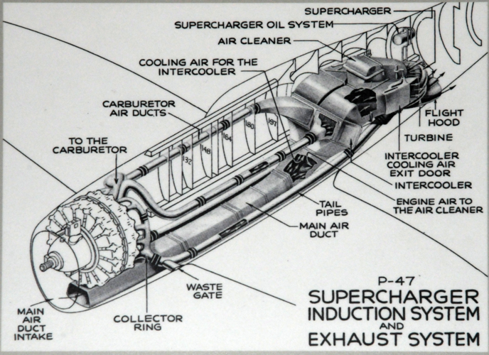
A parallel development was the upright V engines designed by Hispano-Suiza (license-built by Klimov in the USSR) that were still upright Vs. but added auto-cannons nestled between the two banks of cylinders. HS needed the propeller speed reduction unit to raise the thrust line above the crankcase and allow the cannon to fire through the hollow propeller shaft.
HS built their first motor-cannons during World War 1 and installed them on a few SPAD fighters. During WW2, HS motor-cannons were installed on a few French fighters (e.g. Moraine-Saulnier) and most of the Yakovlev fighters.
Installing a motor-cannon interfers with all the intake plumbing in the valley between the Vs, so was only done by a few engine manufacturers (Hispano-Suiza and Klimov).

Germany was the odd-man-out with the inverted V engines built by Mercedes-Benz and Junkers. Inverted V engines start with a high-mounted crankshaft, but negate that by installing a PSRU that lowers the thrust line allowing a motor-cannon to be installed in the "valley" between the cylinder banks, but BELOW the crankshaft. Mounting the thrust line below the crankshaft forces landing gear legs to be longer. Inverted V engines only have an advantage in slant visibility along the sides of the nose. An extreme example is the triangular fuselage of the Me.262 jet.

An obscure example is the inverted V air-cooled engines built by Ranger during the 1940s. When Ranger installed a 520 horsepower, V-770, inverted V-12 engine in the Bell XP-77 light fighter, they installed a PSRU that RAISED the thrust line above the crankcase and allowed installation of a 20mm auto-cannon ABOVE the crankcase. This high thrust line allowed for short landing gear and a triangular engine cowling for better visibility alongside the nose.
 
There is not one perfect solution for all applications, e.g. radial engines were highly sucssessfull as aircraft engines, but not in the automotive or marine enviroment.

Inverted aero engines were not uncommon before WW2, the Menasco engines were also inverted and I believe there is still a decentdant of them in production in the Czech Republic.
 
I would say it does match the pilots point of view, please take a look on the first posting of this thread.
 
The amount of refraction is very angular and glass thickness sensitive so the 109 is a very different to the 190. Therefore you can’t assume the same viewing angle applies to both. Also steep angle come with other real world drawbacks such as sunlight glint and ghosting. There’s an informative explanation of this in an Avro Arrow documentary where they show the effects of different angles and thickness’s.
 
Hi,

View attachment 733418
I have made a very professional paint diagram of what I meant.

It's a good illustrative diagram, but the relative location of the propeller to the crankcase is more appropriate for early direct-drive engines, while the WW2-era fighter engines had a reduction gear in front of the crankshaft that displaced the propeller shaft towards the longitudinal axis of engine, in upright and inverted engines alike. I believe that was actually a requirement for the installation of an engine cannon, as the cannon couldn't fire through the crankshaft, as it would have to do on a direct-drive engine, but it could be made to fire through the displaced propeller hub which had a centreline running between the cylinder banks.

The German preference for inverted engines seems to go back at least to the 1921 textbook by H. Dechamps and K. Kutzbach, "Prüfung, Wertung und Weiterentwicklung von Flugmotoren", where it was suggested as a future design objective. So when the RLM specified an inverted layout for military engines in the 1930s, they were not actually coming up with something new at all ... :)

Regards,

Henning (HoHun)
 
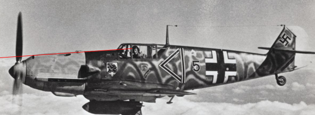
Note that the pilot sits quite close to the windscreen. Something unlikely to be maintained for more than a minute. Even less likely during manoevring.
 
I respectfully disagree. Moving from an upright posture to a reclining posture lowers the head.
 
he is bent forward, so in an upright position, his eyes would be definately higher. Please feel free to find a better picture...
 
Last edited:
Hi Arjen,

Note that the pilot sits quite close to the windscreen. Something unlikely to be maintained for more than a minute. Even less likely during manoevring.

I find it really difficult to assess cockpit visibility from pictures alone.

Here's a page from a US manual that shows forward visiblity of different US fighters:


It would be quite interesting to see similar graphs for more aircraft types, of course.

Note that there might actually be a difference between the shooting view and the "search view", in which the pilot's eye doesn't need to be aligned with the sightline of the gunsight.

Regards,

Henning (HoHun)
 
I find it really difficult to assess cockpit visibility from pictures alone.
So do I.
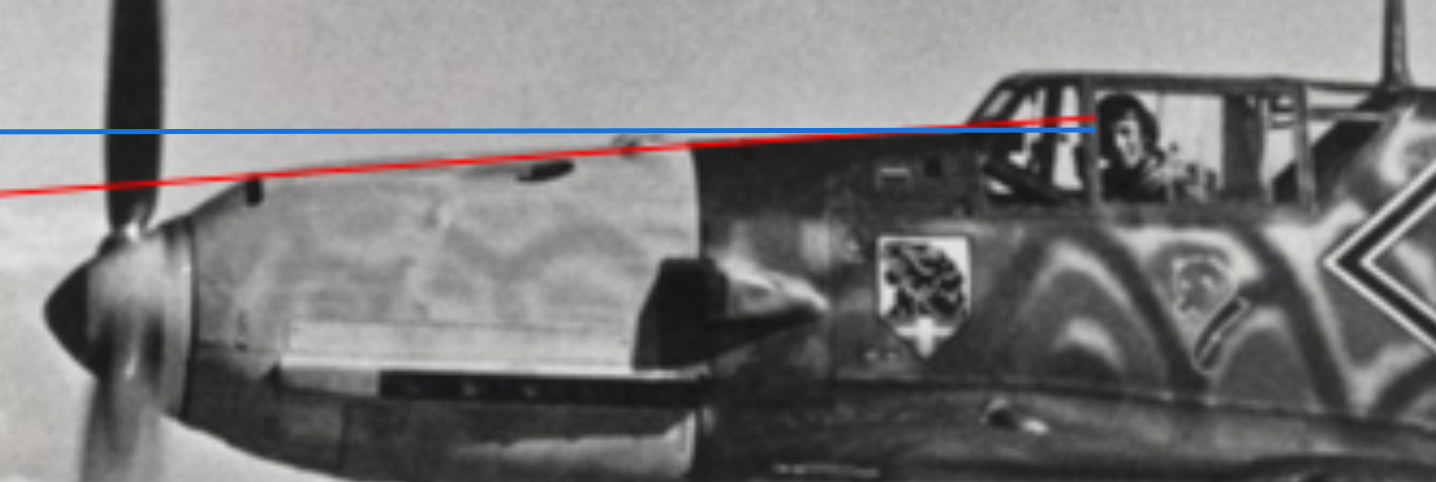
I noticed the red line ended at the pilot's hairline (the edge of his flying cap, to be precise), so I added a blue line that runs from the pilot's eyes through the lower edge of the windscreen. Make of it what you will.
Line of sight.png
 
Hi Arjen,

So do I.
I noticed the red line ended at the pilot's hairline (the edge of his flying cap, to be precise), so I added a blue line that runs from the pilot's eyes through the lower edge of the windscreen. Make of it what you will.
View attachment 733896

For the sighting view, you can use the gunsight - which in the photograph is visible as a box protuding into the cockpit below the windscreen - as a clue. However, it would probably be better to use a technical drawing for this, as relying on a single photograph isn't very accurate due to perspective and distortion issues, and photogrammetry requires multiple (somewhat) coordinated pictures (and is fairly complicated to begin with).

For the Me 262, I've seen drawings in which the lower limit of the sightline was explicitely indicated, but I haven't seen anything like that for the Me 109. In the Me 262 drawing, the difference between an armour glass windscreen and a non-armoured perspex windscreen was one degree extra depression for the sightline, if I remember correctly, but of course the Me 262's windscreen is flatter than the Me 109's, so the effect wouldn't be as pronounced there. (But still present, so one couldn't simply draw a straight line through the technical drawing and get accurate results.)

Here's a thread in a German forum demonstrating how the effect or the armour glass can be calculated if the relevant geometric dimensions are known:


Regards,

Henning (HoHun)
 
@Arien, there are two bumbs on the "hood" on some Me109, which are not in the way when looking along the symetry axis, so the horizontal line which you have drawn is wrong.

Anyhow, we're getting of topic, as I wrote right from the start:

"The A-engine configuration surly didn't help looking backwards and also not in looking along the symmetry axis forward. The improvement was in looking slightly downwards and sideways in frontal direction."

The biggest advantage of the A-engine configuration for the visibility was surly the much improved night vision by taking the exhaust flames out of the view.

Personally, I would be more intrested in the aerodynamic effects of A and V engine configurations, since I believe the A engine might bring a little advantage. The frontal area can be slightly reduces since the engine is only wide at the bottom where the fuselage has to be widend anyway to match the wings and the slightly triangular shape of the fuselage might reduce interference drag somewhat.
 
The German preference for inverted engines seems to go back at least to the 1921 textbook by H. Dechamps and K. Kutzbach, "Prüfung, Wertung und Weiterentwicklung von Flugmotoren", where it was suggested as a future design objective. So when the RLM specified an inverted layout for military engines in the 1930s, they were not actually coming up with something new at all ... :)

Regards,

Henning (HoHun)
Hello,

In a few sources I've read the main reason for inverting the engine is ease of maintenance. Due to the high stance of taildragger aircraft if a mechanic wanted to access the cylinder heads he would have had to keep his hands in an unnaturally high position for a very long time. It would also require him to find a ladder if he wanted to access anything mounted behind the cylinders (armament, intake manifolds etc.).
The A engine layout solves most of those problems without providing any sizable disadvantage.
 
It's surly one aspect, but I doubt that this was the main reason. The Germans really loved the idea of shooting through the porpeller and this was in my view the man driving force behind it. However, there was surly a list with pros and cons, and all these combined was the basis fof the A-configuration, but we might never find out, which one war rated as top priority.
 
Any time one is shooting through the propeller, one needs an offset gearbox. It can be done just as easily with an upright or inverted V. The inverted engine adds the problem of oil draining into the cylinders when the engine is not being read, just as happens with radial engines. Other than that? It's just preference. The French and Soviets had no trouble with cannon firing through the hub with upright V engines. The British (and Americans) seemed to have decided there was more important stuff to put between the cylinder banks than ordnance.
 
Hi,

The French and Soviets had no trouble with cannon firing through the hub with upright V engines. The British (and Americans) seemed to have decided there was more important stuff to put between the cylinder banks than ordnance.

Well, to field an effective engine cannon, you need both an effective cannon and a competive engine that allows its installation. The French had both because Hispano-Suiza offered both - I'm not sure how much input the military had, it might have been driven by Hispano-Suiza as far as I can tell. The Germans had both (for much of the war) as the result of a deliberate development policy. The Soviets had based their main fighter engine on the Hispano-Suiza line, so they sort of inherited the capability to install engine cannon, and they also had suitable cannon types.

When it comes to the British and the Americans, I don't think that they made a deliberate decision not to use engine cannon. The British expected the main mission of their fighters to be interception of unescorted German bombers, and held the opinion that a large pattern was actually advantageous in air combat. I don't believe they ever asked for an engine capable of accepting a cannon installation, despite Britain buying manufacturing rights for the Hispano cannon which originally was an engine cannon.

The Americans actually must have liked the idea of centreline armament, since the P-39's cannon determined the entire layout of the aircraft. It was not really an engine cannon of course, but I'd argue that was not because they thought there was something more important to put between the cylinder banks than the cannon. In my opinion, it's just that neither was the engine well-suited for installation of a cannon, nor was the cannon well-suited for installation in an engine. The P-39's unusual layout was really the only reasonable way they could have done it.

However, I'd agree with you that a cannon installation can be done equally well with either a upright or an inverted V engine. Kutzbach and Deschamp in fact don't mention the cannon in their book, but talk about the drag of the engine, and actually attribute the suggestion of an inverted V engine to Georg Madelung.

Regards,

Henning (HoHun)
 
The Americans actually must have liked the idea of centreline armament, since the P-39's cannon determined the entire layout of the aircraft. It was not really an engine cannon of course, but I'd argue that was not because they thought there was something more important to put between the cylinder banks than the cannon. In my opinion, it's just that neither was the engine well-suited for installation of a cannon, nor was the cannon well-suited for installation in an engine. The P-39's unusual layout was really the only reasonable way they could have done it.
Hello,

As far as I'm aware the love for the 37mm cannon was exclusive to Bell Aircraft who tried fitting that cannon in most of their designs. The only other company that I know of that considered using a 37mm cannon in their designs was Republic with their XP-69 and Republic Rocket.
 
Hello,

As far as I'm aware the love for the 37mm cannon was exclusive to Bell Aircraft who tried fitting that cannon in most of their designs. The only other company that I know of that considered using a 37mm cannon in their designs was Republic with their XP-69 and Republic Rocket.
I believe the USAAC specified the 37 mm in several projects.
 
The pictures right at the beginning of this thread shows, that only the inverted engine with a low mounted canon allowed a line of fire which ran through the CG of the plane. When the line of fire does not match the CG the plane will deviate when firing.
 
Hi,

As far as I'm aware the love for the 37mm cannon was exclusive to Bell Aircraft who tried fitting that cannon in most of their designs. The only other company that I know of that considered using a 37mm cannon in their designs was Republic with their XP-69 and Republic Rocket.

It also was used by Lockheed on the XP-58, I believe, and considered for the Hughes D-2 (that morphed into the XF-11 reconnaissance aircraft).

However, continued USAAF institutional interest in this cannon is evidenced by the post-war Aberdeen Proving Ground trials, where the 37 mm cannon was evaluated alongside the 0.50" and 0.60" heavy machine guns, against 20 mm-calibre cannon, and the German 30 mm MK108.

That we didn't see it on more USAAF single-engined fighters probably is owed to the size of the cannon making such an installation mostly impractical, especially as a "European-style" engine mount wasn't possible due to the size and configuration of the weapon and its ammunition feed.

Regards,

Henning (HoHun)
 
Ging back to the P39: It is very logic, that this design was very well suited for a cannon firing through the propeller, but accoding to my knowledge, the P39 was also originally intended to have turbochargers which was also a driving force behind the design. Turbochargers needed much romm back than and a rear engine position would have helped.
 
Ging back to the P39: It is very logic, that this design was very well suited for a cannon firing through the propeller, but accoding to my knowledge, the P39 was also originally intended to have turbochargers which was also a driving force behind the design. Turbochargers needed much romm back than and a rear engine position would have helped.

In the Bell Model 4 prototype (XP-39), the single GE turbosupercharger - as it were then called - sat directly beneath the engine. It was the intercooler that was positioned behind the V-1710 (in an apparently very 'draggy' installation).
 
It propably had a simillar draggy turbocharger outlet geometry like the P38. The intercooler had no boundary seperation, this is surly less efficient than the intake from the Mustang. It would have had a superior aerodynamics if it was developed later in the war...
 
Last edited:
The pictures right at the beginning of this thread shows, that only the inverted engine with a low mounted canon allowed a line of fire which ran through the CG of the plane. When the line of fire does not match the CG the plane will deviate when firing.
Hello,

whether or not the cannon is aligned with the CG or not does not depend on the design of the engine but only on the way it is mounted. additionally due to the thickness of the crankcase, accessories and various other equipment most engines have their center of gravity in between the cylinders so a plane with an upright engine can accept an engine of a reversed configuration with minimal modifications.
 
Hi,


It also was used by Lockheed on the XP-58, I believe, and considered for the Hughes D-2 (that morphed into the XF-11 reconnaissance aircraft).

However, continued USAAF institutional interest in this cannon is evidenced by the post-war Aberdeen Proving Ground trials, where the 37 mm cannon was evaluated alongside the 0.50" and 0.60" heavy machine guns, against 20 mm-calibre cannon, and the German 30 mm MK108.

That we didn't see it on more USAAF single-engined fighters probably is owed to the size of the cannon making such an installation mostly impractical, especially as a "European-style" engine mount wasn't possible due to the size and configuration of the weapon and its ammunition feed.

Regards,

Henning (HoHun)
Hello,

I have to apologize as I wrote that post in a manner that doesn't convey my point in a proper way. My point is that while almost every US aviation company considered using a 37mm cannon in one of their projects these were very one-off occasions that I believe never went through into service with such an armament. Bell and Republic were the only companies that used that cannon at scale in many designs.
 
Ging back to the P39: It is very logic, that this design was very well suited for a cannon firing through the propeller, but accoding to my knowledge, the P39 was also originally intended to have turbochargers which was also a driving force behind the design. Turbochargers needed much romm back than and a rear engine position would have helped.
Indeed the P-39 was designed in such a way to allow for the installation of a turbocharger with streamlining and armament being secondary in that decision. While turbochargers are not extremely big in aviation the accessories needed to run them are numerous and bulky.
Zrzut ekranu 2024-07-10 185139.png
 
Hello,

whether or not the cannon is aligned with the CG or not does not depend on the design of the engine but only on the way it is mounted. additionally due to the thickness of the crankcase, accessories and various other equipment most engines have their center of gravity in between the cylinders so a plane with an upright engine can accept an engine of a reversed configuration with minimal modifications.
The clash was between installing a cannon between the cylinder banks or installing intake piping. Intake piping was HUGE issue during WW2 as all the engine manufacturers were struggling to master super-chargers and turbo-chargers.
Hispano-Suiza and Klimov solved the problem by routing intake piping in the valley between the cylinder banks and ABOVE the cannon and routing exhaust outboard.
Meanwhile Allison and Rolls-Royce filled that "valley" with intake piping.
 
Hi,

My point is that while almost every US aviation company considered using a 37mm cannon in one of their projects these were very one-off occasions that I believe never went through into service with such an armament. Bell and Republic were the only companies that used that cannon at scale in many designs.

Thanks for the clarification! My take on the issue is:

- The 37 mm cannon was obviously considered an attractive weapon by the USAAF from the pre-war to the immediate post-war era, and I am confident that whenever it was included in a project, it was upon suggestion by the USAAF or in appreciation of the USAAF's preference for this weapon.
- At the same time, it was not a suitable weapon for an "engine cannon"-type installation.
- Nor had the Allison V-1710, which had been developed for the US military, been required to be suitable to accommodate such an installation, for example with regard to supercharger placement and general component packaging.
- The P-39 proves that the USAAF was aware of the advantages of a centreline cannon armament, to the point of accepting the negative side of the tradeoffs required to make it work with a combination of a not quite suitable cannon and a not quite suitable engine, and putting into production as one of their main early-war fighter types.
- So I don't believe the USAAF ever deliberately decided that they didn't want engine cannon, or made a design (requirement) trade-off that favoured anything else over cannon-suitability of the V-1710 (except perhaps development time).

The continental European Vee engines show that it's possible to design an engine for engine cannon without much of an impact on engine size or performance. The Jumo 213, which I believe Calum Douglas considers one of the best engines of WW2, was suitable for cannon installation, too. It's just that if you don't make cannon-suitability a requirement right from the start, it's very unlikely the engine can be re-designed to accommodate a cannon later.

Regards,

Henning (HoHun)
 
Hi again,

Here's a page from a US manual that shows forward visiblity of different US fighters:


It would be quite interesting to see similar graphs for more aircraft types, of course.

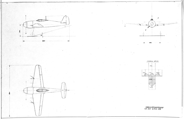
I just saw an even more detailed diagram showing the visibility from the cockpit of the very early (BMW 139-powered) Focke-Wulf Fw 190 in this post by Sienar:


For reference, here's the relevant drawing:

190 139 3 view.png

The bottom right schematic is labeled "Sichtfeld 62,5 %" = 'Field of Vision 62.5%'.

The cross-shaped diagram is a development of a cube, and the captions on each square read (vertically down), "Top", "Front", "Bottom", "Aft", with the arms of the cross being "Left" and "Right".

You could basically cut out this diagram, fold it up into a cube, and placing yourself in the centre of the cube, get an exact picture of the field of view of the pilot in that Fw 190 prototype.

Really neat, I wish we had these diagrams for every aircraft! :)

Regards,

Henning (HoHun)
 
Hello,

whether or not the cannon is aligned with the CG or not does not depend on the design of the engine but only on the way it is mounted. additionally due to the thickness of the crankcase, accessories and various other equipment most engines have their center of gravity in between the cylinders so a plane with an upright engine can accept an engine of a reversed configuration with minimal modifications.

If we are talking about a typical WW2 low wing single engine fighter, the CG will be quite low, the wing, wingtanks and the landing gear are all very deep. In this case, for a V engine with a cannon in it’s V and the line of fire matching the CG, it would have to mounted so low, that it protudes out of the bottom.
 
Just a thought on machine guns and V-12 engines.
In the interwar period the RAF moved away from synchronised machine guns firing over the engines in favour of synchronised machine guns mounted abreast the cockpit and this layout was used in both radial and V-12 engined fighters. So the Kestrel-powered fighters tended to have their gun troughs running below the cylinder head and therefore not increasing the cross-section of the fuselage or drag.

The Germans tended to stick with the synchronised machine guns firing over the engines all the way from 1915 to 1945 and the inverted-vee of course has its widest point lower in the fuselage and more space with which to mount machine guns over it. Allied to the propeller shaft gun, this gives a fairly concentrated volume of fire. I wonder if this influenced the choice of inverted Vees?
 
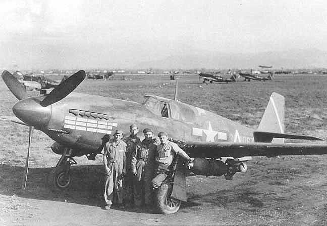
If you lack space on top of the engine, try what North American did. Image of A-36 with 0.5in machine gun below the engine:
1000007546.jpg
There could be some drawbacks to this solution, I can't recall any other single-engine aircraft type with guns below the engine.
 
The pictures right at the beginning of this thread shows, that only the inverted engine with a low mounted canon allowed a line of fire which ran through the CG of the plane. When the line of fire does not match the CG the plane will deviate when firing.
The engine thrust line also needs to go through the CG or you'll constantly have to re-trim the plane as you change power settings.

So if you had an upright V engine with a cannon firing through the hub, it wouldn't throw the plane out of whack.

And you'd have a couple of feet more ground clearance for bigger props.
 
I highly doubt this is the case, if you take e.g. a look on the spitfire, the heavey wings, landing gear the armament is all deep below the trust line.

When power settings are changed, the plane will deviate anyway, but during firing operation the pilots will most likely not have played with the trust lever.
 
There could be some drawbacks to this solution, I can't recall any other single-engine aircraft type with guns below the engine.
I believe that the fact of the pilot not being able to see the tracers for a very significant part of their flight time could have an impact on this.
 

Similar threads

Please donate to support the forum.

Back
Top Bottom