- Joined
- 26 May 2006
- Messages
- 34,869
- Reaction score
- 15,733
Hi,
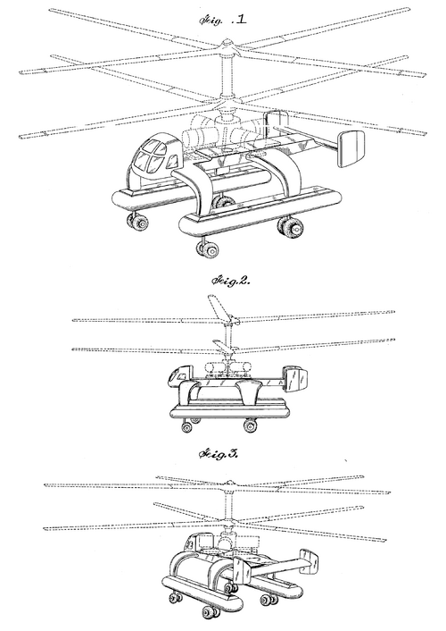
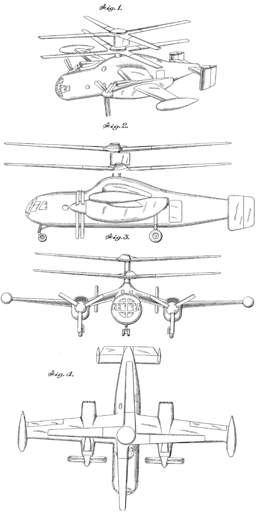
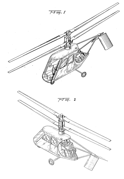
a two helicopter Projects from Gyrodyne,one of them was an UAH.
a two helicopter Projects from Gyrodyne,one of them was an UAH.
Attachments
Last edited:
hesham said:a two helicopter Projects from Gyrodyne,one of them was an UAV.
http://www.aviodyne.com/ROTORCYCLE.html
Maveric said:GCA.24 ? the pics say Model 21...


The source;From my dears Stargazer and Boxkite,
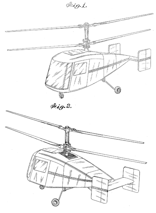
the Gyrodyne GCA.33,it was two seat light helicopter,this project
called for two two-bladed coaxial contra-rotating rotors powered
by one 150 hp Lycoming engine,estimated speed 121 km/h and
range 193 km.
Aviation Week, 16 Jan 1950Convertaplane Prototype Tested
Wingless configuration used in initial trials to provide data for planned rescue version with stub wings.
Concurrent with the growing interest in convertaplanes, the Gyrodyne Co. of America, Inc., has brought out its experimental prototype “Helidyne” and has projected plans for an arctic rescue version and a combination troop carrier—cargo-hospital craft.
These designs are intended to eliminate aircraft-turnover and propeller—displacement features of other configurations.
Bendix Coaxial Used—The company purchased Helicopters, Inc. (formerly Bendix Helicopter, Inc.) in September 1949, and for its wingless prototype
Helidyne has adapted the Bendix coaxial rotary wing configuration powered by a P&W 450-hp. engine. Auxiliary power for pr0viding forward thrust through tractor propellers is by two 100-hp. Continentals (souped up from rated 83-hp.) carried on either side of the aft fuselage.
The prototype convertaplane was first flown on Nov. 30, 1949. On Dec. 5 and 6, the craft was flight—evaluated at Fitzmauriec. Field, Massapequa, New
York, by a USAF pilot team. Speeds during these tests were only at half throttle, equivalent to approximately 75 mph. at 2.100 rpm. for each auxiliary
engine.
Theory—With this configuration, the company merely wanted to demonstrate that when propulsive force is available from an auxiliary source and not from the main rotors, the rotor blade pitch requirements will be considerably less than in conventional helicopter forward flight; consequently, blade stall
will take place at a much higher speed. In addition, the craft flies forward in a level, rather than inclined, attitude.
Since the auxiliary engines provide the thrust which normally would be supplied by the rotors, the feathering requirements of the rotors are reduced,
consequently flapping of the blades is also lessened. And reduction in flapping affords reduction in vibration from this source.
>Version Planned—The proposed aretic rescue version is projected as an amphibian utilizing sealed fuselage and stub wings, the latter functioning as
sponsons. Craft would be powered by two 375-bp. Lycomings carried above the wings and driving both rotors and propellers, with shafts to the rotors through streamlined struts. It is intended that the configuration will be capable of single-engine performance as a helicopter.
At low speeds and for landings and takeoffs, the craft would perform as a helicopter, with the pusher propellers declutched. For fast forward flight, propellers would be engaged, the wing picking up lift to unload the rotors, and the airplane—type empennage becoming effective. With transition complete, the major portion of the lift would be carried by the wing, the rotors functioning for lateral control only.
>Cruise At ISO—Normal gross weight is expected to be 6800 lb.; cruising speed, 150 mph. at 5000 ft.; top speed, 162 mph. The craft is projected to accommodate 6 litters or afford space for 9 passengers in addition to the two—man crew. At alternate gross of 7600 lb. it would seat 10 passengers.
The design features clam—shell doors at fuselage rear, together with traveling crane carriage and power hoist for loading in hovering. Mounting of the engines outside of the fuselage will improve soundproofing characteristics, providing for greater passenger comfort. And because of the coaxial rotor configuration to be employed, storage of the craft will be facilitated with the blades aligned in the fore—and-aft position.
Overall height of the configuration would be 15 ft.; rotor diameter, 50 ft.; fuselage length, 20 ft.; wing span, 26 ft.; unobstructed cabin would be 10
ft. long, 5.5 ft. wide, and have a 6ft. high aisle.
Production plans are not yet complete, but the company expects to have an arctic version prototype ready before end of 1950. A scaled—up projection of this craft. having a 25.000-lb. gross, is being planned as cargo—troop carrier-hospital feeder plane, with cruising speed estimated at over 200 mph.
ULTIMATE DESIGN, planned to be built as arctic rescue version with sealed fuselage and wings, latter acting as sponsons. Engines, carried above wings, are specified as 375-bp. Lycomings for driving both the rotors and the propellers.
The article mentionsAviation Week, 16 Jan 1950Convertaplane Prototype Tested
Wingless configuration used in initial trials to provide data for planned rescue version with stub wings.
Concurrent with the growing interest in convertaplanes, the Gyrodyne Co. of America, Inc., has brought out its experimental prototype “Helidyne” and has projected plans for an arctic rescue version and a combination troop carrier—cargo-hospital craft.
These designs are intended to eliminate aircraft-turnover and propeller—displacement features of other configurations.
Bendix Coaxial Used—The company purchased Helicopters, Inc. (formerly Bendix Helicopter, Inc.) in September 1949, and for its wingless prototype
Helidyne has adapted the Bendix coaxial rotary wing configuration powered by a P&W 450-hp. engine. Auxiliary power for pr0viding forward thrust through tractor propellers is by two 100-hp. Continentals (souped up from rated 83-hp.) carried on either side of the aft fuselage.
The prototype convertaplane was first flown on Nov. 30, 1949. On Dec. 5 and 6, the craft was flight—evaluated at Fitzmauriec. Field, Massapequa, New
York, by a USAF pilot team. Speeds during these tests were only at half throttle, equivalent to approximately 75 mph. at 2.100 rpm. for each auxiliary
engine.
Theory—With this configuration, the company merely wanted to demonstrate that when propulsive force is available from an auxiliary source and not from the main rotors, the rotor blade pitch requirements will be considerably less than in conventional helicopter forward flight; consequently, blade stall
will take place at a much higher speed. In addition, the craft flies forward in a level, rather than inclined, attitude.
Since the auxiliary engines provide the thrust which normally would be supplied by the rotors, the feathering requirements of the rotors are reduced,
consequently flapping of the blades is also lessened. And reduction in flapping affords reduction in vibration from this source.
>Version Planned—The proposed aretic rescue version is projected as an amphibian utilizing sealed fuselage and stub wings, the latter functioning as
sponsons. Craft would be powered by two 375-bp. Lycomings carried above the wings and driving both rotors and propellers, with shafts to the rotors through streamlined struts. It is intended that the configuration will be capable of single-engine performance as a helicopter.
At low speeds and for landings and takeoffs, the craft would perform as a helicopter, with the pusher propellers declutched. For fast forward flight, propellers would be engaged, the wing picking up lift to unload the rotors, and the airplane—type empennage becoming effective. With transition complete, the major portion of the lift would be carried by the wing, the rotors functioning for lateral control only.
>Cruise At ISO—Normal gross weight is expected to be 6800 lb.; cruising speed, 150 mph. at 5000 ft.; top speed, 162 mph. The craft is projected to accommodate 6 litters or afford space for 9 passengers in addition to the two—man crew. At alternate gross of 7600 lb. it would seat 10 passengers.
The design features clam—shell doors at fuselage rear, together with traveling crane carriage and power hoist for loading in hovering. Mounting of the engines outside of the fuselage will improve soundproofing characteristics, providing for greater passenger comfort. And because of the coaxial rotor configuration to be employed, storage of the craft will be facilitated with the blades aligned in the fore—and-aft position.
Overall height of the configuration would be 15 ft.; rotor diameter, 50 ft.; fuselage length, 20 ft.; wing span, 26 ft.; unobstructed cabin would be 10
ft. long, 5.5 ft. wide, and have a 6ft. high aisle.
Production plans are not yet complete, but the company expects to have an arctic version prototype ready before end of 1950. A scaled—up projection of this craft. having a 25.000-lb. gross, is being planned as cargo—troop carrier-hospital feeder plane, with cruising speed estimated at over 200 mph.
View attachment 678964ULTIMATE DESIGN, planned to be built as arctic rescue version with sealed fuselage and wings, latter acting as sponsons. Engines, carried above wings, are specified as 375-bp. Lycomings for driving both the rotors and the propellers.
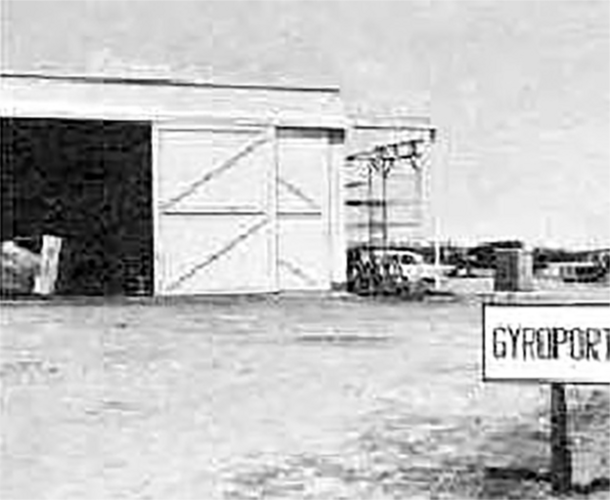


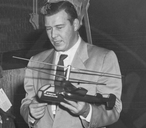
Also in that thread Stargazer2006 writes of an „GCA-12 [that] was an HR Class Interim Assault helicopter proposal for U. S. Marine Corps”.
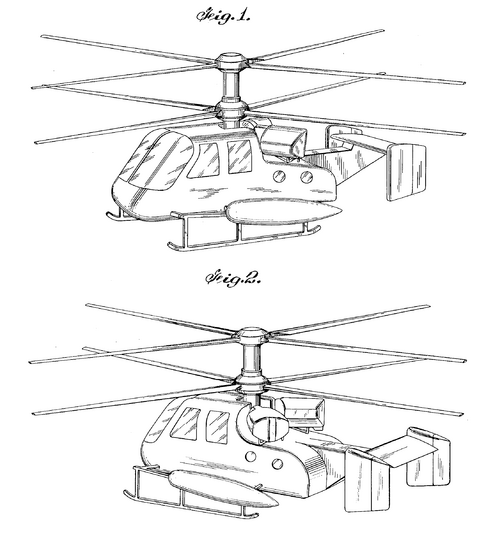
So there at least two elusive Gyrdyne designs here, the 9 Helidyne ASW from the XHP competition (this thread) and the CGA-12.
Aerofiles lists none of them (http://aerofiles.com/_gr.html) although from what I gather they tend to include proposals that existed on paper only.
I'm pretty certain this is the Gyrodyne 9 Helidyne. The cockpit similarities to other XHP entries is pretty marked.
GYRODYNE
After the end of World War II, during which Peter J. Papadakos worked with various aircraft manufacturers, he brought together a group of engineers to produce a helicopter with a better performance than any of those existing at the time. This group became the nucleus of the present Gyrodyne Company of America Incorporated (GCA).
In the early 1950s Gyrodyne settled on the co-axial configuration and concentrated its efforts on perfecting helicopters of this type. The invention of the rotor-tip brake control system for directional flight was the key to the successful development of GCA’s co-axial helicopters. It was planned that they should take off vertically and yet possess greater horizontal cruising speed and range than the traditional helicopter. Encouraged by its first results, the company has done developmental work on other projects, including a large-scale rotorcraft designed to carry seventy passengers.
1949 GCA-2A
This is the Bendix 1947 Model J (q.v.) acquired by GCA and modified by adding on each side of the fuselage a 100 h.p. engine carried on an outrigger. These engines gave equal thrust and could operate independently. The co-axial contra-rotating rotors worked continuously; in horizontal flight the cyclic pitch variation of the blades was obviously less than that required in a normal helicopter. The tests of this rotorcraft were intended to provide basic data for the company’s programme of developing compound aircraft. The first flight took place at the end of November 1949.
Engines (3); one Pratt and Whitney R-985, 450 h.p., and two Continental C85-12, 100 h.p. each
Length: 21 ft 3 in (6.48 m)
Height: 14 ft 3 in (4.34 m)
Rotor diameter: 48 ft (14.63 m)
Number of seats: 4-5
1952 GCA-2C
This version resembled its predecessor in some respects but differed in being a pure helicopter with two co-axial contra-rotating two-bladed rotors of semi-rigid type, and incorporating automatic locks which prevented flapping at low rotor speeds. The entire transmission system contained only five gears altogether. The engine was situated just behind the rotor blade axle, and there were also twin fins and rudders. It should be observed that a system of co-axial rotors working on the same principle was incorporated in the Gyrodyne Rotorcycle XRON-1.
Engine: Pratt and Whitney R-985, 450 h.p.
Length: (overall) 18 ft (5.49 m)
Height: 14 ft 4 in (4-37 m)
Rotor diameter: 48 ft (14.63 m)
Weight empty: 3,800 lb (1,724 kg)
Weight fully loaded: 5,400 lb (2-449 kg)
Cruising speed: 89 m.p.h. (143 k.p.h.)
max: no m.p.h. (177 k.p.h.)
Inclined climb: 1,460 ft/min (445 m/min)
Absolute ceiling: 22,100 ft (6,736 m)
Range: 270 miles (435 km)
Number of seats: 6
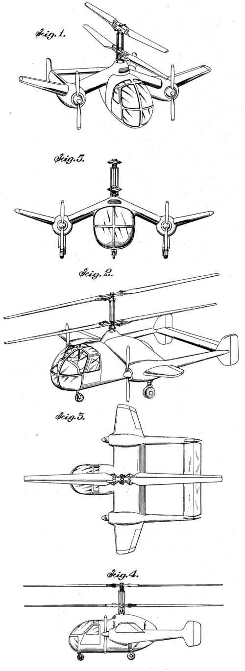
1951 GCA-3 HELIDYNE (project)
This project for a convertiplane was to have two co-axial contrarotating rotors, and on each side of the fuselage a stub wing with an outboard engine and airscrew. During horizontal flight these engines would provide forward propulsion. The Helidyne thus combined the features of a helicopter and a twin-engined fixed-wing aircraft.
Engines (2): Pratt and Whitney R-1340, giving 1,200 h.p. in all
Length: 31 ft 10 in (9.7 m)
Height: 16 ft 9 in (5.11 m)
Rotor diameter: 62 ft (18.9 m)
Weight empty: 7,800 lb (3,538 kg)
Weight fully loaded: 11,000 lb (4,990 kg)
Cruising speed: 125 m.p.h. (201 k.p.h.)
Inclined climb: 1,090 ft/min (332 m/min)
Absolute ceiling: 18,900 ft (5,760 m)
Range: 294 miles (473 km)
Number of seats: 18
1949 GCA-5 (project)
This project differed from others made by the same company in that it called for a single rotor instead of the usual two co-axial rotors. The single rotor was to have four blades rigidly attached to a universal mounted hub, so that the general configuration was that of one main and one antitorque rotor. The tail rotor, however, was to be movable so that in translational flight it could tilt and take up the position of an airscrew. Normally, the tail rotor absorbed 80 per cent of the available power, and only the remaining 20 per cent was left over for the main rotor. When the tail rotor was swung aft, with a simultaneous increase in pitch, the pitch of the main rotor was decreased and it thus absorbed even less power.
Engine: 274 h.p.
Rotor diameter: 36 ft (10-97 m)
Weight empty: 2,035 lb (923 kg)
Weight fully loaded: 2,795 lb (1,268 kg)
Cruising speed: 155 m.p.h. (249 k.p.h.)
Range: 264 miles (425 km)
Number of seats: 3
1949 GCA-7 (project)
This project was designed to change the machine from a helicopter into a fixed-wing aircraft with gradual increase in forward speed. On each side of a wide fuselage a stub wing carried an engine driving pusher propellers. The latter could be declutched for take-off and for landing, i.e. when the aircraft was used as a helicopter. The GCA-7 was to be amphibious. The entire lower structure and also the wings were to be sealed and waterproofed so that landings could be made on water without floats.
Engines (2): Lycoming GSO-580, 375 h.p.
Width: (stub wing) 26 ft (7.92 m)
Rotor diameter: 52 ft (15.85 m)
Weight empty: 4,646 lb (2,107 kg)
Weight fully loaded: 7,600 lb (3,447 kg)
Cruising speed: 150 m.p.h. (241 k.p.h.)
Inclined climb: 1,300 ft/min (396 m/min)
Absolute ceiling: 8,800 ft (2,682 m)
Range: 250 miles (402 km)
Number of seats: 12 (2 crew, 10 passengers)
1949 GCA-8 Gyroliner (project)
This was to be a scaled-up version of the Helidyne and large enough to carry as many passengers as a good-sized transport aircraft. The engines were to be placed on stub wings and be fitted with propellers.
Rotor diameter: 90 ft (27.43 m)
Weight empty: 27,000 lb (12,247 kg)
Weight fully loaded: 40,000 lb (18,144 kg)
Cruising speed: 280 m.p.h. (451 k.p.h.)
Number of seats: 56 (2 pilots, 54 passengers)
1949 GCA-9 (project)
This project for a ‘Helidyne Transport’ with co-axial configuration was to be developed more especially as a rotorcraft for use in feeder line service.
Engines (2): 600 h.p.
Rotor diameter: 62 ft (18-9 m)
Weight empty: 7,800 lb (3,538 kg)
Weight fully loaded: 13,000 lb (5,897 kg)
Cruising speed: 160 m.p.h. (257 k.p.h.)
Number of seats: 18 (1 pilot, 17 passengers)
1951 GCA-21 (project)
This project for a freight rotorcraft was to have the company’s usual co-axial configuration, and to be powered by a turboprop engine.
Engine: Allison turboprop equivalent to 5,000 s.h.p.
Rotor diameter: 100 ft (30.48 m)
Weight empty: 18,000 lb (8,165 kg)
Weight fully loaded: 52,500 lb (23,814 kg)
Cruising speed: 75 m.p.h. (121 k.p.h.)
Range: 65 miles (105 km)
1955 GCA-24 (project)
This was a project for a cargo helicopter or flying crane, designed to carry a cargo pack. The design embodied as before two co-axial contra-rotating two-bladed rotors shaft-driven by gas-turbine engines.
Engines (2): turboprop, equivalent to 3,500 s.h.p. each
Rotor diameter: no ft (33.53 m)
Weight empty: 21,630 lb (9,812 kg)
Weight fully loaded: 70,000 lb (31,751 kg)
Cruising speed: 90 m.p.h. (145 k.p.h.)
Inclined climb: 1,000 ft/min (305 m/min)
Number of seats: 3
1954 GCA-32 (project)
This project for a convertiplane followed the company’s usual configuration of two co-axial contra-rotating four-bladed rotors, together with stub wings and airscrews.
Engines (2).- Wright, 800 h.p.
Rotor diameter: 60 ft (18.29 m)
Weight fully loaded: 14,000 lb (6,350 kg)
Cruising speed: 160 m.p.h. (257 k.p.h.)
Absolute ceiling: 18,500 ft (5,639 m)
Range: 140 miles (225 km)
Number of seats: 7
1955 GCA-33 (project)
This project called for two two-bladed co-axial contra-rotating rotors powered by a single engine.
Engine: Lycoming, 150 h.p.
Rotor diameter: 28 ft (8-53 m)
Weight fully loaded: 1,600 lb (726 kg)
Cruising speed: 75 m.p.h. (121 k.p.h.)
Absolute ceiling: 14,500 ft (4,420 m)
Range: 120 miles (193 km)
Number of seats: 2
1954 GCA-35 gyroliner (project)
The design of this high-speed convertiplane called for a power source consisting of two turboprop engines, as in the GCA-24. It was to have wings and airscrews on either side and the rotary wing was to have two co-axial contra-rotating two-bladed rotors.
Engines (2): turboprop, equivalent to 7,000 s.h.p. each
Rotor diameter: 88 ft (26-82 m)
Weight fully loaded: 77,000 lb (34,927 kg)
Cruising speed: 230 m.p.h. (370 k.p.h.)
Inclined climb: 2,350 ft/min (716 m/min)
Range: 500 miles (805 km)
Number of sea ts: 70
1956 GCA-41 (XRON-1 ROTORCYCLE)
This portable single-seater helicopter with two co-axial contra-rotating two-bladed rotors, developed for the United States Navy, had its first trials in 1956. The Rotorcycle, which benefited from the progressive development of the special rotor system in the same company’s Model 2C, was originally meant to be fitted with a 44 h.p. Nelson engine. This was later replaced by a 62 h.p. Porsche engine. Another version has also been tried with a Solar YG-62 Titan shaft-turbine. The Rotorcycle can be folded up into a small package for transport purposes.
Engine: Porsche GP-702-1, 62 h.p.
Length: 11 ft 6 in (3.52 m)
Height: 8 ft (2.44 m)
Rotor diameter: 17 ft (5.18 m)
Weight unloaded: 425 lb (193 kg)
Weight fully loaded: 690 lb (313 kg)
Cruising speed: 45 knots (83 k.p.h.)
Inclined climb: 600 ft/min (183 m/min)
Service ceiling: 6,500 ft (1,981 m)
Range: 51 nautical miles (94 km)
Number of seats: 1
1959 GCA-59 (YRO-1 Rotorcycle)
Of the same type as its predecessor, this Rotorcycle, for which the U.S. Navy designation is YRON-1, has a rotor with a slightly larger diameter and is fitted with an engine specially developed by the firm of Porsche of Stuttgart in Germany. This version was evaluated at the U.S. Naval Air Test Centre, Patuxent River, Maryland, and later by the U.S. Marine Corps.
Engine: Porsche YO-95-6, 72 h.p.
Height: 9 ft (2-74 m)
Rotor diameter: 20 ft (6-i m)
Weight unloaded: 550 lb (249 kg)
Weight fully loaded: 832 lb (377 kg)
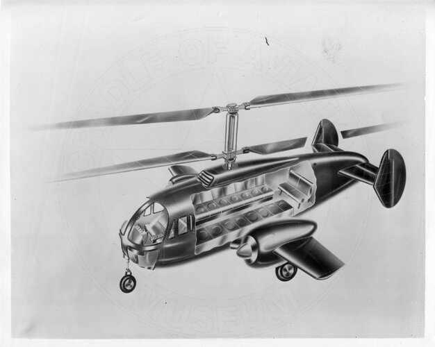
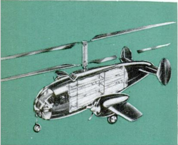
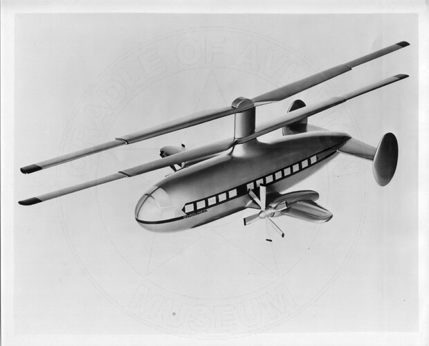
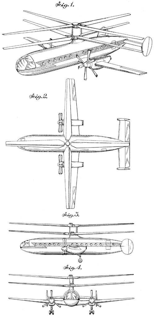
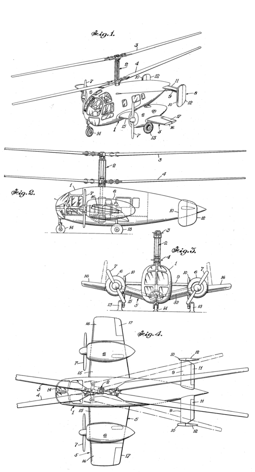

Gyrodyne GCA-12 (Model 12)
Possibly a convertiplane project with coaxial rotors (not built)
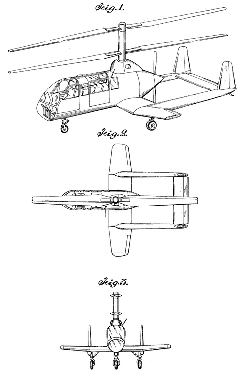
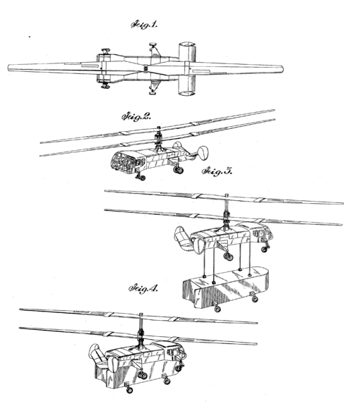
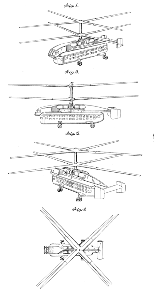
Gyrodyne GCA 15 (Model 15)

Note the number 15 written on the model.

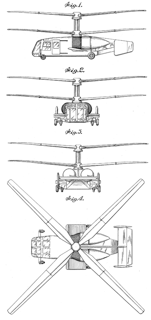
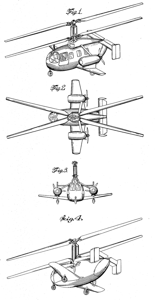
Design Patent USD172712 (Nov 1951)
