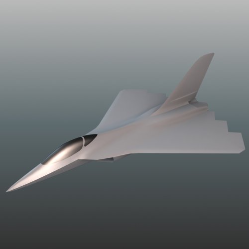
General Dynamics ATF CGI Model

Evil Flower

ACCESS: Secret
Joined
12 October 2006
Messages
223
Reaction score
59
Found this in the other thread and thought it looked really cool with it's Batwing-like appearance so here's a stab at modelling it in 3D.


As an aside, does anyone know if drawings were ever produced showing the layout of the landing gear and weapons carriage, or should I assume these to be similar to what we saw on the YF-22 (since the fuselage contours are kind of similar)?
 

Attachments

  • pers.jpg
    pers.jpg
    372.4 KB · Views: 1,697
Yeah those pod thingies. What you see is just a couple hours worth of work getting the main shape blocked out. The intention is to add all the details to it and then import it into a suitable sim engine like SF2.
 
I think you're safe in assuming the landing gear design is similar to the YF-22's, as IIRC, the gear design for the YF-22/F-22 came from the GD submission, in terms of having low to the ground for crewman to work on from the ground. Their paper on easily maintainable fighters has a similar stance. It's the GD configuration 700, which you can search here at SP. It might be in a GD ATF/Pre-ATF thread.

Here you go GD Config 700. I'm sure it's elsewhere on here in other threads as well, but you just need the pics for ref. I mean you can see how low to the ground it is. I think the gear on the GD ATF works more like the F-22's though, do the missile bay requirements for the ATF.

Nice model, I'd love to fly it in FSX.

BTW, which modeling package are using? Max, Rhino3D?
 
I wonder if it has a YF-22 type weapon bay or a rotary bay like on the Lockheed ATF submission.
 
Nils_D said:
I wonder if it has a YF-22 type weapon bay or a rotary bay like on the Lockheed ATF submission.

Coming along nicely!
I thought there was a GD patent related to the weapons bay, but I was not able to find it.
 
Given the similarities of the lower fuselage design, I think they were probably alike. I would say make some inlet ducts similar to the F-22's and look at what volume you need for the main gear to retract and see if there is anough room for sidewinders on the sides and AMRAAMs on the bottom. It's hard for me to tell, because I don't have a dimensional reference in front of me right now for this design. That's one of the design aspects I found interesting about the GD submission. It probably looks smaller than it actually is.
 
Thats awesome. Note that General Dynamics never finalised the vertical tail design as they couldn't make it work - therefore a production GD ATF would have to have a different vertical tail arrangement.

Its obvious how much F-16XL DNA went into this design.
 
Thanks! The canopy on this thing is pretty huge. I used the YF-22 and 23s as scale reference so this thing has a span of about 13.5 meters with 18.5 meters long, so about the size of an F-15. Even then it's pretty tricky to find the space for 6 missiles. And I have no idea where they put the gun since they used the LERX to fit the radar arrays.
 
Thanks Nils, i'm also an airplane modeler here is my topic in this forum :
http://www.secretprojects.co.uk/forum/index.php/topic,16147.0/all.html
i think you are also in military-meshes, anyway what i want to know is how did attempt to model those hard edges in this aircraft because i want to model a Stealth UAV designed by me and it has hard edges.

thanks again
 
Nah, I don't post at military meshes. Either way, modelling the hard edges is pretty simple: Use different smoothing groups and/or add extra edges to bevel edges that need to be smooth yet sharp. Also if you use meshsmooth you can check "use smoothing groups" and it will keep those edges hard while smoothing the rest.
 
The General Dynamics Design

The General Dynamics design for the dem/val phase evolved from a variety of inputs. During the previous program phase, the company had focused on three separate families of aircraft: conventional, all-wing, and semi-tailless (denoted in the configuration studies by C, W, and T, respectively). The conventional family derived from the Model 21 designs of the previous studies. The all-wing family strove to carry Sneaky Pete's minimum observables into the supersonic regime. The semi-tailless family, which had a single vertical tail, fell in between these two extremes. After a series of internal design competitions and trades, the company went with the semi-tailless approach.

The wing planform and airfoil design were chosen to minimize weight while providing the maximum turn capability and supersonic cruise. The single vertical tail, however, presented problems in achieving a totally stealthy design. General Dynamics ran many wind tunnel tests to find a location and shape for twin canted vertical tails on the T configuration. The vortex flow off the forebody and delta wing produced unstable pitching moments when it interacted with twin tails. Without horizontal tails, the aircraft did not have enough pitch authority to counteract these moments. A single vertical tail and no horizontal tails was finally identified as the best overall approach to the design despite the degradation of radar cross section in the side sector. The proposal configuration was designated T-330.

General Dynamics took a unique approach to the sensor requirements, using two radar arrays and one infrared search and track sensor. (Boeing and Lockheed had each used three arrays and two IRST sensors.) One IRST sensor was placed in the nose of the aircraft and the two radar arrays were located aft of the cockpit. The radar beam from each array could be steered sixty degrees from the face of the array, allowing each radar to cover the area from straight ahead to 120 degrees aft. The arrays were located just above the engine inlets.

General Dynamics configuration achieved a high state of detailed design. The company had built a full-scale mockup and was finalizing a half-size pole model for testing the design's radar cross section. Preliminary structural designs were developed, along with locations for manufacturing breaks to allow the aircraft to be divided among potential partners. General Dynamics had done well in the concept exploration phase of the program, placing very high in the field of seven. Among General Dynamics strengths were its extensive experience in fighter design and manufacturing gained in the F-16 program. The company also had experience with rapid prototyping: the YF-16 was an unsurpassed program in this respect.

F-22 Design Evolution
Reprinted article from Code One Magazine, April 1998, Vol.13 No.2
 
More pics. I'm considering deleting the sidebays since they are kind of too tight a fit. However that leaves only 4 AMRAAM as armament. It'd be nice to see some drawings or photos of the actual mockup that GD built.
 

Attachments

  • pers2.jpg
    pers2.jpg
    343.3 KB · Views: 811
  • pers3b.jpg
    pers3b.jpg
    389.6 KB · Views: 758
very nice!


Advanced Tactical Fighter to F-22 Raptor: Origins of the 21st Century Air Dominance Fighter, by David C. Aronstein, Michael J. Hirschberg, & Albert C. Piccirillo, AIAA 1998 - confirms that GD ATF had weapon bays positioned just like on YF-22
 
Alright! The AIM-9s are a really tight fit in the sidebays atm though so perhaps the landing gear needs to be moved back? The position of it looks about right, though, CG-wise and using YF-22 as a guide.
 
Partly it might be the way you have it packaged. You have the sidewinders aligned with the aircraft center line, which will increase the size of the bay. If you angle them nose out, so you have the same clearance to the outer mold line with the front sidewinder fins as you do the rear, it will make more room for where the inlets sweep in toward the center of the fuselage. Also, make sure that you have them mounted in an X configuration where the two tips of a side of the X (Representing the fin sidewinder fin configuration) are aligned with the slope of the outer fuselage wall where the bay doors are. This should minimize the size of you bay and maximize internal volume. Edit: Looking at the pics you may have done this already but it's difficult to tell from the images posted.

Also, angling them nose out would make the launcher more simple, since, based on how the F-22 launches its Sidewinders, they're angled out at launch. Which I assume is to make sure there is a minimum chance of the aircrafts near field aero causing them to fly into the aircraft.

Also, it looks like you have side bays too far forward. Look at a good bottom view of the F-22 and you'll see the side bays are further back along the aircraft. I would propose you convert the main landing gear into the style the production F-22 uses. This would allow you to move the side bays further back, since the MLG bay won't extend so far forward anymore.

It's looking really good so far.
 
Any chance the central bay is narrow and deep, and holds a stack of more missiles than 4?
 
chuck4 said:
Any chance the central bay is narrow and deep, and holds a stack of more missiles than 4?

No. That would add too much frontal area and take up too much internal volume. The original F-22 held four as well. The only reason they can have six now is due to staggered mounting in the main weapons bay and the redesign of the missiles.
 
Sundog said:
Also, it looks like you have side bays too far forward. Look at a good bottom view of the F-22 and you'll see the side bays are further back along the aircraft. I would propose you convert the main landing gear into the style the production F-22 uses. This would allow you to move the side bays further back, since the MLG bay won't extend so far forward anymore.
I've been thinking about this. The YF-22 and F-22 have more space due to being somewhat longer than the GD design. I'm not sure about changing the gear as teh wing is too thin to house the wheel and I think the YF-22 type gear is more plausible, being much like an F-16 gear mounted on a wider body.
 
Something looks off with that GD ATF bay. At the time the GD ATF was being designed only the AIM-120A/B existed and not the clipped-fin AIM-120C as shown in the picture.

Just like in the F-22, if you can hold 4 AIM-120A/B then you should be able to hold 6 AIM-120C.
 
Those are AIM-120As, I'm afraid. Like I said the plane is smaller than the F-22 judging by the canopy which would otherwise be disproportionally big. Also the main source of reference has been the YF-22 which IIRC was only capable of carrying 4 missiles in the center bay due to 4 AIM-120A being the requirement.
 
If the gear is flipped 180 dgs to retract backwards instead of forwards, the gear bays can be moved backwards and that would give more than ample space for the AIM-9 bays. Make sense?
 

Attachments

  • gearswitch.jpg
    gearswitch.jpg
    46.7 KB · Views: 553
a variant, but historically, aircraft designers prefer landing gears to be retracted forth (as it's easier to them to extract and lock by own weight in airstream in case of hydraulics failure)
but in case of limited space why knows...
 
Well, I did some remodelling and test-fitting and came up with this. The wheels are at the same distance from CG as before but the tires are somewhat smaller to fit into smaller bays which themselves have been moved back to make place for the Sidewinder bays.
 

Attachments

  • newbays.jpg
    newbays.jpg
    473.7 KB · Views: 1,221
  • newbays_side.jpg
    newbays_side.jpg
    371.3 KB · Views: 1,174
  • bottom.jpg
    bottom.jpg
    377.5 KB · Views: 1,055
This model is turning out great. I really enjoy seeing it coming together like that. Nils_D, you should consider contacting one of those game studios making combat sims for mobile devices. I am sure they will be interested in making this model available for gameplay.


On another note, the vertical tails seams like completely out of place with the rest of the design. I wish I coud read some trade studies about why GD thought single tail is better than say no tail with & two larger winglets option. I can't see any benefit than say better roll performance.
 
It is well documented :

The wing planform and airfoil design were chosen to minimize weight while providing the maximum turn capability and supersonic cruise. The single vertical tail, however, presented problems in achieving a totally stealthy design. General Dynamics ran many wind tunnel tests to find a location and shape for twin canted vertical tails on the T configuration. The vortex flow off the forebody and delta wing produced unstable pitching moments when it interacted with twin tails. Without horizontal tails, the aircraft did not have enough pitch authority to counteract these moments. A single vertical tail and no horizontal tails was finally identified as the best overall approach to the design despite the degradation of radar cross section in the side sector. The proposal configuration was designated T-330.
 
Yes Paul, I clearly remember that passage ;) , which is why I asked specifically why single tail was chosen over no tail with winglets, not two tails. I personally think the passage you mentioned referred to this configuration a the same one but with the tail canted inward.

atf9.jpg


While I was referring to the following configuration with winglets which as least I don't consider vertical tails.

atf11.jpg


IMHO the vortices generated by the forebody and the the delta wing would have passed on the inside of the winglets roughly over the center of the wing in a similar way the ones on the F-22 do appear here

2818204323_f48ea689af.jpg


So since both of those two configurations would have had greater range and lower side RCS, not to mention being sexier, I think the 3D model wil be much better of if it looked like the last one but that's just me.
 
There may have been a weight penalty for using such winglets/wingtip-mounted tails, as the wings may have needed to be reinforced to translate the loads from them to fuselage.
 
lantinian said:
Yes Paul, I clearly remember that passage ;) , which is why I asked specifically why single tail was chosen over no tail with winglets, not two tails. I personally think the passage you mentioned referred to this configuration a the same one but with the tail canted inward.

2818204323_f48ea689af.jpg

I don't suppose you have a high rez version of that somewhere do you? (Nice pic.)
 
I know this is from a long time ago, but other advantages of a large single tail are spin properties.

Also, at moderately high alpha (30 deg) a single tail will typically see cleaner airflow as it lies along the right/left mirroring plane. The vortices from the leading edge extensions also add a vertical component at the wing tips and subtract a vertical component at the fuselage center. This sucks the air down towards the central vertical stabilizer, adding to the velocity across the vertical stabilizer because the plane is at an upwards angle.

You can see that the flow at (1) across the tail is straighter than the flow at (2). The twin vertical tails on the GD ATF would increase pressure at the rear because of the lateral flow (2) and would cause a diverging pitch-up moment.

Putting rudders at the wingtips of a delta is generally not an aerodynamically good idea due to the strong spanwise flow at the tips.

Although the pictures I included below are not of the GD ATF (I would be happy to perform some CFD on it), it helps give a visual of the flow field of an aircraft with a strong LEX or delta configuration. The model shown is of the Fairchild F-X.
 

Attachments

  • Fairchild F-15 001 - 0.5 Mach - 30 deg alpha - 0 deg beta - 0 throttle - Image 002A.PNG
    Fairchild F-15 001 - 0.5 Mach - 30 deg alpha - 0 deg beta - 0 throttle - Image 002A.PNG
    321.8 KB · Views: 150
  • Fairchild F-15 001 - 0.5 Mach - 30 deg alpha - 0 deg beta - 0 throttle - Image 003A.PNG
    Fairchild F-15 001 - 0.5 Mach - 30 deg alpha - 0 deg beta - 0 throttle - Image 003A.PNG
    229.9 KB · Views: 174
Actually, twin tails usually have better spin resistance, since when the aircraft is in spin, one of the vertical tails will be in good airflow coming between the wing and the horizontal tail, whereas a single tail has tendency to be blanked out by most of the fuselage.
 

Similar threads

Please donate to support the forum.

Back
Top Bottom