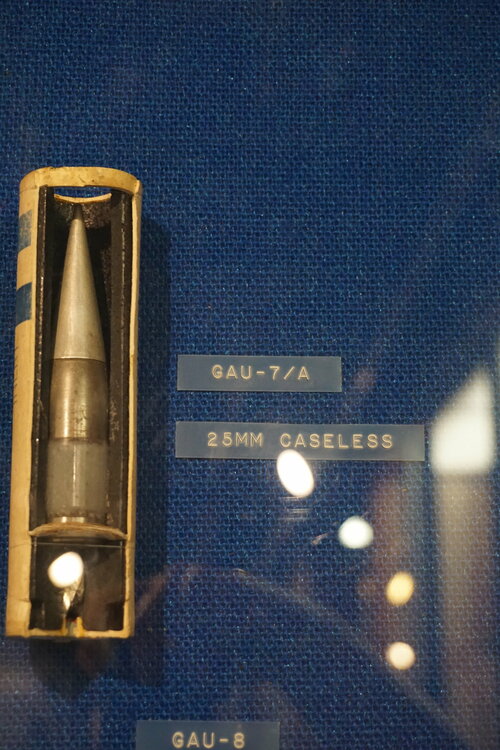
This is where all the felting operations took place, and the one building I wish I had documented before we gutted it for scrap. The combustible cases were made from a slurry of craft paper and nitrocellulose pulp that was coated onto forms, vacuumed, cured, resin dipped & then cured again - essentially making an explosive cardboard. There were enormous stainless steel tanks, pumps, slurry mixers, various mechanisms and all the controls for all of it when we got here. All this required an insane amount of water. There's a 200,000 gallon tank that fed this building alone. Between that and the 300,000 fire suppression tank, there were five well houses with 20hp submersible pumps, and an additional five wells drilled, but never used. There was a time when the small surrounding town got their water from Brunswick. The large ditch you see in the ground in front of the building was dug out as the expansion pond for drainage from manufacturing operations.
IMG_1229-50%25.JPG


This is just a shot of some of the lower buildings as seen from the hill with the charge press building. The two on the left were mostly receiving warehouses. I don't know the original purposes for the ones on the right, but they were being used in the 80's for various aircraft & mobile shelter parts plating. Some F117 work was done in that second building from the right in the early 80's. You can see the office building up on the left.

You can also see a little bit of the buildings up the hill back in the trees. That's where the really nasty stuff took place with the CS gas production.
IMG_1230-50%25.JPG


But wait - there's more! Some documentation & work instructions I scanned.


Phase IV technical proposal. Starts with "Section III" and I have no idea what sections 1 or 2 were.
http://crunchysuperman.freeservers.com/brunswick/GAU7A Phase IV.pdf


Operator work instructions for outer case felting.
http://crunchysuperman.freeservers.com/brunswick/outer case instructions.pdf


Air Force report after an attempt was made to switch from nitrocellulose to plastic for the outer case material. I didn't scan this one, but rather found it online during some investigations.
http://crunchysuperman.freeservers.com/brunswick/GAU-7A Brunswick.pdf
 
Fascinating - thanks!

Brunswick also made radomes and other "plastic" aircraft parts. Was this location strictly the ammunition?

Enjoy the Day! Mark
 
Are there any legible photos or technical information of the (competing?) GE 225 twin-barrel 25mm gun anywhere out there?
 
Fascinating - thanks!

Brunswick also made radomes and other "plastic" aircraft parts. Was this location strictly the ammunition?

Enjoy the Day! Mark

The first Brunswick plant local to me was originally recreation products only (bowling pins, pool tables, etc.). They built the facility on the farm in the early 60's as their first foray into defense work. Right around the time the 25mm project was cancelled, the first plant also transitioned into defense work, mainly radomes (which they still do to this day). Not long after, they built two more facilities near the first one for other defense projects and relegated the farm for plating operations to support the other 3 plants and also used many of the buildings for overflow storage. Brunswick sold all 4 plants to ATP in the early 90's and the farm facility was auctioned off at that time. Soon after, ATP was acquired by General Dynamics and plants 1-3 are still going strong today.

edit - didn't really answer the question

Aside from the 25mm project, I know they made illumination flares, grenade fuses, 2.75" rockets, and a lot of CS gas with various types of delivery systems. I also found a technical proposal for caseless tank rounds, but I don't know if it ever went any further than that.
 
Last edited:
View attachment 628444
From my forthcoming book:

25 mm GE-225: 25 x 137 ammunition.

The impressive combination of compact size, light weight and high rate of fire demonstrated by the Russian twin-barrel (Gast type) GSh-23 attracted General Electric's attention in the early 1980s. This prompted a design study focused on the standard 25 mm NATO ammunition. The resulting GE-225 was designed to be as modular and flexible as possible to suit it to different purposes, even a choice of externally-driven or gas-operated mechanisms.Overall length is 221 cm. The weight of 82 kg is impressive given the rate of fire of up to 2,500 rpm. Despite this promising performance, this went no further.

GE carried out an interesting comparison exercise between various different 25 mm gun configurations, both actual and proposed. The diagram (Chinn V page 372) illustrates the guns in the following table:

GUN TYPE BARRELS RoF WEIGHT rpm/kg

M242 Chain 1 500 119 4.2

Oerlikon KBA gas 1 600 112 5.4

Mauser Model E gas 1 900 103 8.7

GE 225 Gast 2 2,000 82 24

CHAG 225 rotary 2 2,000 112 18

GE 325 rotary 3 2,400 120 20

GAU-12 rotary 5 4,000 160* 25
 
Fascinating - thanks!

Brunswick also made radomes and other "plastic" aircraft parts. Was this location strictly the ammunition?

Enjoy the Day! Mark

The first Brunswick plant local to me was originally recreation products only (bowling pins, pool tables, etc.). They built the facility on the farm in the early 60's as their first foray into defense work. Right around the time the 25mm project was cancelled, the first plant also transitioned into defense work, mainly radomes (which they still do to this day). Not long after, they built two more facilities near the first one for other defense projects and relegated the farm for plating operations to support the other 3 plants and also used many of the buildings for overflow storage. Brunswick sold all 4 plants to ATP in the early 90's and the farm facility was auctioned off at that time. Soon after, ATP was acquired by General Dynamics and plants 1-3 are still going strong today.

edit - didn't really answer the question

Aside from the 25mm project, I know they made illumination flares, grenade fuses, 2.75" rockets, and a lot of CS gas with various types of delivery systems. I also found a technical proposal for caseless tank rounds, but I don't know if it ever went any further than that.
Thanks! I have a photo album of various aircraft related parts - radomes, fin tips, fairings and the like that were being produced by Brunswick at the time the album was put together. They are also listed on many of the McDonnell aircraft subassembly drawings for those items. Always nice to fill in the history blanks - thanks!

Enjoy the Day! Mark
 
This building contains the production line and presses for the forward & aft propellant charges. It appears that this line was added later to what was originally a generic work building. You can see the front half of the building is comprised of huge concrete "cubicles" whose walls go up through the roof. The ceiling & back walls were flimsy so that if you blew up, the blast went up & backwards while not spreading to the station next to you. Many of the buildings were made this way. The plywood awning enclosure was added to house the conveyor that moved the pressed & dried charges to the back of the building for further assembly. The exhaust stacks were added and those workrooms were turned into drying rooms to oven-cure the charges. You can see at the far end of the building that the roof of two of the "cubicles" have been enclosed. Those are where the elevators to the press hoppers are.
IMG_1233-50.JPG


This is the forward charge press. It's very difficult to get good pictures of these machines, as they take up every last inch of the stall where they were mounted.
IMG_1236-50.JPG


This is the elevator that delivered the powder to the hopper at the top of the press (the reason for the extended roof in the outside pic of the building). Note the conveyor on the right that moved the finished charge down the line.
IMG_1237-50.JPG


Control area for the charge press. You can see the machine through the glass a little bit. That glass is about 4 inches thick. Out of frame to the left is the control for the aft charge with a window looking through to a similar press room. Out of frame to my right is the conveyor moving all the finished charges down the line.
IMG_1239-50.JPG


As the charges came out of the presses, employees would apparently load them into those racks you see in that pile. They hang from the overhead conveyor that you can barely see in this shot. That tank would elevate and dip each rack before proceeding through the drying ovens.
IMG_1235-50%25.JPG


More of the conveyor. You can see the partially open shutter door coming out of the last oven room.
IMG_1234-50%25.JPG


Here's a closer shot of one of the press controls.
IMG_1240-50.JPG


Better shot of that dip tank entrance to the ovens.
rsz_img_20131001_182400_772.jpg
damn that's a lot of equipment. Did you try and sell any of it or was it basically junk by then?
 
This is where all the felting operations took place, and the one building I wish I had documented before we gutted it for scrap. The combustible cases were made from a slurry of craft paper and nitrocellulose pulp that was coated onto forms, vacuumed, cured, resin dipped & then cured again - essentially making an explosive cardboard. There were enormous stainless steel tanks, pumps, slurry mixers, various mechanisms and all the controls for all of it when we got here. All this required an insane amount of water. There's a 200,000 gallon tank that fed this building alone. Between that and the 300,000 fire suppression tank, there were five well houses with 20hp submersible pumps, and an additional five wells drilled, but never used. There was a time when the small surrounding town got their water from Brunswick. The large ditch you see in the ground in front of the building was dug out as the expansion pond for drainage from manufacturing operations.
IMG_1229-50%25.JPG


This is just a shot of some of the lower buildings as seen from the hill with the charge press building. The two on the left were mostly receiving warehouses. I don't know the original purposes for the ones on the right, but they were being used in the 80's for various aircraft & mobile shelter parts plating. Some F117 work was done in that second building from the right in the early 80's. You can see the office building up on the left.

You can also see a little bit of the buildings up the hill back in the trees. That's where the really nasty stuff took place with the CS gas production.
IMG_1230-50%25.JPG


But wait - there's more! Some documentation & work instructions I scanned.


Phase IV technical proposal. Starts with "Section III" and I have no idea what sections 1 or 2 were.
http://crunchysuperman.freeservers.com/brunswick/GAU7A Phase IV.pdf


Operator work instructions for outer case felting.
http://crunchysuperman.freeservers.com/brunswick/outer case instructions.pdf


Air Force report after an attempt was made to switch from nitrocellulose to plastic for the outer case material. I didn't scan this one, but rather found it online during some investigations.
http://crunchysuperman.freeservers.com/brunswick/GAU-7A Brunswick.pdf
Great post. I worked in the office building from 1972-1974. Did analyses on performance of all the R&D rounds fired. Have many interesting stories.
 
Chamber and barrels moving at different RPM? o_O

That seems like it's just begging for trouble... you have timing/synchronization issues with getting the chamber to line up with the barrel, and then you need to seal the gap between the two...

I'm also struck by the lack of a backup gun plan for this. GAU8 had the competing GAU9, GAU7 didn't have anything but the old M61.
 
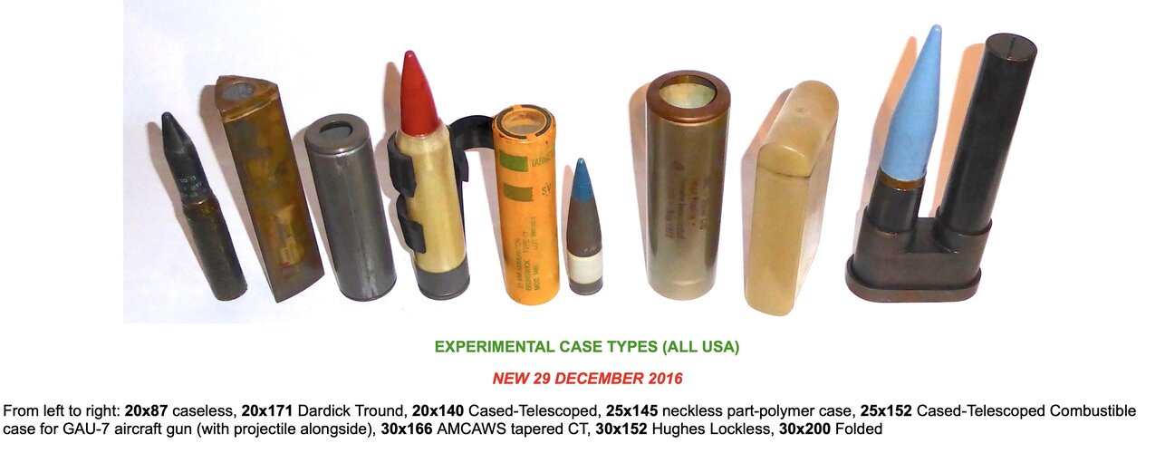
What's the story of the Dardick round?
Those weird triangular case-telescoped things?

The idea was that it's a revolver cannon that doesn't need a dedicated mechanism to feed the triangular round ("tround") into the revolver part. The revolver cylinder is open on the outside and the trounds are fed directly into the side of the cylinder.

Here's a couple deep dives into the pistol that was the proof of concept for the Dardick MG:
Forgotten Weapons:
View: https://youtu.be/psrZXa2WeQE?si=CU3iNHTCliCaEbvB

Anvil Gunsmithing:
View: https://www.youtube.com/watch?v=N5w_QbIDwys
 
While digging around MRCA weapons files in Kew, I came across a handwritten briefing from August 1969 on guns for the IDS variant (High Performance Aircraft Gun). Amongst the ADEN, DEFA and Oerlikons, a pair of US weapons was mentioned, intended for the 'F15':

General Electric 25mm Aircraft Gun - eight chamber, six-barreled, caseless 25mm gun
Philco-Ford 25mm Aircraft Gun - eleven chamber, five-barreled, caseless 25mm

As ever, I came across this as the minders were chucking me out by on my last day.

Chris
 
Last edited:
While digging around MRCA weapons files in Kew, I came across a handwritten briefing from August 1969 on guns for the IDS variant (High Performance Aircraft Gun). Amongst the ADEN, DEFA and Oerlikons, a pair of US weapons were mentioned, intended for the 'F15':

General Electric 25mm Aircraft Gun - eight chamber, six-barreled, caseless 25mm gun
Philco-Ford 25mm Aircraft Gun - eleven chamber, five-barreled, caseless 25mm

As ever, I came across this as the minders were chucking me out by on my last day.

Chris
That doesn't even make sense to me. I get the concept of a revolver cannon and a gatling gun, but that is just bizarre.
 
General Electric 25mm Aircraft Gun - eight chamber, six-barreled, caseless 25mm gun
Philco-Ford 25mm Aircraft Gun - eleven chamber, five-barreled, caseless 25mm

This must be earlier on in the design process, the Philco-Ford gun that appears in Chinn has 9 chambers, and the General Electric design 10 chambers.
 
How would that work, having more chambers than barrels on a gatling gun?

Having the barrel cluster rotate slower than the chamber cluster, and arrange for the firing to occur when the two are lined up?
10 chambers : 5 barrels means a 2:1 reduction
9 chambers : 6 barrels would be a 3:2 reduction
As to why - Better heat management than a revolver cannon (because multiple barrels) but less weight than a pure gatling design with the same number of chambers?
 
Do any existing modern gatling-type guns have more chambers than barrels like that? It seems like it would add a lot of complexity for limited gain. The requirements for the new gun must have been very (seemingly overly) ambitious. With 5 or 6 barrels and the same number of chambers you can already fire upwards of 4,000 rounds per minute of 25mm shells, how much more do you need to shred an enemy aircraft? At a certain point the rate of fire would empty the ammo drum too fast to do any good.

Maybe a reason was due to the caseless ammunition generating more heat when fired? No shell case to absorb some of the thermal energy.
 
Do any existing modern gatling-type guns have more chambers than barrels like that?
Not that I am aware of.


Maybe a reason was due to the caseless ammunition generating more heat when fired? No shell case to absorb some of the thermal energy.
That's what I'd expect. I keep hearing that some 40% of the heat generated on firing is held in the casing and removed from the gun that way. So you'd need a pretty fancy ceramic that could withstand gun-firing shock loads as the chamber.

(replacing the G11 rotary breech/chamber with a ceramic part has been my suggestion for improvements to that design. That and summoning the ghosts of John Moses Browning, Gene Stoner, and Mikhail Kalashnikov to simplify the freaking swiss watch of internal bits in there...)
 
Wait! What's this? 27x70B "1950's large-caliber M61 Vulcan variant," you say?
I believe 27mm rounds were also evaluated alongside 20mm rounds when the Vulcan was being developed, with the latter being selected as a balance between fire rate and muzzle energy.
 

Similar threads

Please donate to support the forum.

Back
Top Bottom