F-16 Inlet Variants

As reported, the F-16 small mouth and large mouth intakes are both pitot normal shock designs.
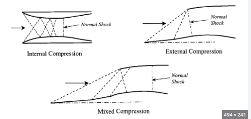
So basically F-16, F-35, Rafale, Eurofighter , Gripen inlet are all external compression inlet to prevent the unstart phenemenon right?. How about F-100 or Mig-19 inlet? Are those two internal compression inlet?. Which one are mixed compression? F-15?
As far as I know, the only mixed compression inlets have been the A-12/SR-71 family and the XB-70. The MiG-25/31 fly fast enough that a mixed compression inlet could be advantageous, but they appear to be variable multi-ramp external compression designs.
That interesting, I have always thought that maybe the shock cone of F-16/rafale/gripen inlet are close enough to the internal that they are essentially mixed compression.
I can only think of Mig-19 and f-100 for internal compression though
I highly doubt that MiG-19 and F100 are mixed compression. They both are more likely to be pitot normal shock by appearance and their low supersonic envelope. It would be very hard to achieve mixed compression over a range of Mach numbers without some variable intake geometry. Maybe the XF8U-3 with its forward swept cowl and large inlet bypass doors, but I’m just guessing based on the projected flight Mach numbers.
I know Mig-19 and F-100 are not mixed compression, I meant, based on their look, I think only them has full internal compression ( no forward plate)
 
The splitter plate is only to separate the boundary layer from the inlet when the inlet is aft of the nose. Not needed when the inlet is the front of the aircraft.

Of course, the DSI inlet on the F-35 and J-20 directs the boundary layer around the inlet opening, so no splitter plate there either.
 
The splitter plate is only to separate the boundary layer from the inlet when the inlet is aft of the nose. Not needed when the inlet is the front of the aircraft.

Of course, the DSI inlet on the F-35 and J-20 directs the boundary layer around the inlet opening, so no splitter plate there either.
I thought the splitter plate also create oblique shock to slow down the supersonic air stream?. That how f-16/rafale make their external compression right?
 
Interesting what could be accomplished with modern CFD, hints of the future?

P&W completes F100-229A altitude testing​

17 February 1998
Pratt & Whitney has completed initial altitude tests of an advanced version of the F100-229A flight engine, which is fitted with a new fan and inlet to boost power and increase durability.

The -229A is designed to power the Boeing F-15E and Lockheed Martin F-16C/D from 2000 onwards - either as a retrofit kit or as a complete engine - and has demonstrated a thrust capability of 165kN (37,150lb). The engine is in competition for US and export business with General Electric's similarly upgraded F110-129EFE (enhanced fighter engine).

Top international priority for both is the long delayed United Arab Emirates (UAE) decision on the potential purchase of Block 60 F-16s. "We're waiting for international and domestic requirements to surface," says P&W F100 programme director Dennis Enos.

Other than the UAE, Greece and Norway are highlighted as near term potentials for the -229A, says Enos, who adds: "That's also why we've made this configuration retrofittable. You can back fit this on the existing -229 by putting the new fan on and shortening the afterburner duct."

Altitude tests of the new fan, which is 25mm larger in diameter than the original -229 unit, have proved "highly successful", says Enos. Testing took place at P&W's Wilgoos test site in Connecticut and verified "-the operation of the fan at high Mach numbers, and all the results were good".
The tests were crucial because the use of the titanium wide chord fan and one piece inlet case has precluded the need for variable fan inlet geometry.

"Using the latest computational fluid dynamics analysis we've been able to design the first fighter engine that does not require a variable inlet, and the Mach 2 tests confirmed we could operate successfully at these speeds," according to Enos.


The simpler inlet and fan have almost 100 fewer parts than those in the standard engine does, and is a major contributor to the increased durability goals of the -229A because they also reduce operating temperature.
"From that standpoint, when we are operating it at 29,000lb [129kN] thrust, we're able to increase the overhaul life from 4,300 cycles to 6,000. So we're looking to increase the time interval to return to the depot by around 40%," says Enos.

The fan increases the overall engine bypass ratio by 10% and has an airflow capability of up to 125kg/s. Despite the increase in bypass ratio, the engine still occupies the same volume as the current -229, allowing it to be developed as a "plug-in" replacement.

Fan module size is increased by 150mm in length, while a similar reduction has been made to the afterburner length. "This turns out to be very successful," says Enos, who adds that rapid accelerations from idle to full afterburner have consistently taken 2s.

Source: Flight International
 
The splitter plate is only to separate the boundary layer from the inlet when the inlet is aft of the nose. Not needed when the inlet is the front of the aircraft.

Of course, the DSI inlet on the F-35 and J-20 directs the boundary layer around the inlet opening, so no splitter plate there either.
I thought the splitter plate also create oblique shock to slow down the supersonic air stream?. That how f-16/rafale make their external compression right?

On the F-4 it did, because the back half surface of the splitter plate on the F-4 actually extended out to become a ramp. There is a slight ramp effect to most splitter plates, but the oblique shock off of those will be quite weak. The normal shock (Meaning the shock is perpendicular to the airflow) does the majority of the work of slowing the flow down to subsonic speeds in pitot type inlets. The expansion in the inlet duct slows it down to the speed optimized for the powerplant. You should also note that the sweep angle of the shock also affects pressure recovery. Note that the F-22's caret inlets mean the shock is a 3D shock (1D is pitot, like the F-100, F-16, F-18, etc., 2D is an oblique shock like on the F-14 and F-15, and 3D is like the F-22. A shock cone is sort of a circular 2D inlet and the F-35 has a complex shock structure that is the result of advanced CFD.) My point being that the sweep of the shock allows more efficient pressure recovery at higher speeds as F119 noted. The most efficient being an isentropic inlet, which has more of a continuously curving ramp, but I don't know that any of those have been built. Partly due to complexity and I'm not sure how well they would perform off of their design point.
 
The splitter plate is only to separate the boundary layer from the inlet when the inlet is aft of the nose. Not needed when the inlet is the front of the aircraft.

Of course, the DSI inlet on the F-35 and J-20 directs the boundary layer around the inlet opening, so no splitter plate there either.
I thought the splitter plate also create oblique shock to slow down the supersonic air stream?. That how f-16/rafale make their external compression right?
The splitter plate can be angled or wedge shaped to create an oblique shock, like was used on the F-16/J79 demonstrator. But production F-16 inlets have a flat splitter and are normal shock designs. F-104 had a fixed half cone mounted on the splitter to create a semicircular oblique shock (slightly better recovery than a flat oblique), F-4 has a shallow wedge splitter with a moving back half to create a 2 oblique shock inlet for better pressure recovery at M2+.
So in short,
Rafale, F-35, F-16, F-100, Mig-19 are all internal compression inlet?
Eurofighter, F-15, F-14, F-104, Mirage, Mig-21 are external compression inlet
Mig-25, Mig-31, SR-71 are mixed compression?
 
The splitter plate is only to separate the boundary layer from the inlet when the inlet is aft of the nose. Not needed when the inlet is the front of the aircraft.

Of course, the DSI inlet on the F-35 and J-20 directs the boundary layer around the inlet opening, so no splitter plate there either.
I thought the splitter plate also create oblique shock to slow down the supersonic air stream?. That how f-16/rafale make their external compression right?

On the F-4 it did, because the back half surface of the splitter plate on the F-4 actually extended out to become a ramp. There is a slight ramp effect to most splitter plates, but the oblique shock off of those will be quite weak. The normal shock (Meaning the shock is perpendicular to the airflow) does the majority of the work of slowing the flow down to subsonic speeds in pitot type inlets. The expansion in the inlet duct slows it down to the speed optimized for the powerplant. You should also note that the sweep angle of the shock also affects pressure recovery. Note that the F-22's caret inlets mean the shock is a 3D shock (1D is pitot, like the F-100, F-16, F-18, etc., 2D is an oblique shock like on the F-14 and F-15, and 3D is like the F-22. A shock cone is sort of a circular 2D inlet and the F-35 has a complex shock structure that is the result of advanced CFD.) My point being that the sweep of the shock allows more efficient pressure recovery at higher speeds as F119 noted. The most efficient being an isentropic inlet, which has more of a continuously curving ramp, but I don't know that any of those have been built. Partly due to complexity and I'm not sure how well they would perform off of their design point.
I thought F-22 inlet is same as F-15, just fixed instead?
 
I thought F-22 inlet is same as F-15, just fixed instead?
No, the F-15 has an external compression ramp inlet, while the F-22 has a caret inlet. The F-15’s inlet has variable ramps are scheduled based on Mach number and flow conditions to trap the terminal shock at the throat, with the edges of the ramps generating oblique shocks. Note that it also has variable capture area. The F-22’s caret inlet has fixed geometry, but is swept roughly symmetrically along multiple axes, with the upper inlet corner generating a pair of oblique shocks ahead of the terminal shock. Shock position is controlled with via downstream pressure rather than mechanical ramps. It enables excellent pressure recovery while also being less mechanically complex and more conducive to stealth.

Regarding isentropic compression ramps, I do believe the Concorde has one behind the first ramp; after the first two oblique shocks, a compression fan is generated by a gradually curving surface.
 
The splitter plate is only to separate the boundary layer from the inlet when the inlet is aft of the nose. Not needed when the inlet is the front of the aircraft.

Of course, the DSI inlet on the F-35 and J-20 directs the boundary layer around the inlet opening, so no splitter plate there either.
I thought the splitter plate also create oblique shock to slow down the supersonic air stream?. That how f-16/rafale make their external compression right?
The splitter plate can be angled or wedge shaped to create an oblique shock, like was used on the F-16/J79 demonstrator. But production F-16 inlets have a flat splitter and are normal shock designs. F-104 had a fixed half cone mounted on the splitter to create a semicircular oblique shock (slightly better recovery than a flat oblique), F-4 has a shallow wedge splitter with a moving back half to create a 2 oblique shock inlet for better pressure recovery at M2+.
So in short,
Rafale, F-35, F-16, F-100, Mig-19 are all internal compression inlet?
Eurofighter, F-15, F-14, F-104, Mirage, Mig-21 are external compression inlet
Mig-25, Mig-31, SR-71 are mixed compression?
SR-71 is mixed compression inlet

Don’t know about MiG-25/31. They appear to be external, multi-oblique with variable ramps, but I could be wrong.

All of the others are external compression, either normal shock (pitot) or oblique shock (ramps or cones, fixed or variable)
 
As reported, the F-16 small mouth and large mouth intakes are both pitot normal shock designs.
So basically F-16, F-35, Rafale, Eurofighter , Gripen inlet are all external compression inlet to prevent the unstart phenemenon right?. How about F-100 or Mig-19 inlet? Are those two internal compression inlet?. Which one are mixed compression? F-15?
As far as I know, the only mixed compression inlets have been the A-12/SR-71 family and the XB-70. The MiG-25/31 fly fast enough that a mixed compression inlet could be advantageous, but they appear to be variable multi-ramp external compression designs.
That interesting, I have always thought that maybe the shock cone of F-16/rafale/gripen inlet are close enough to the internal that they are essentially mixed compression.
I can only think of Mig-19 and f-100 for internal compression though
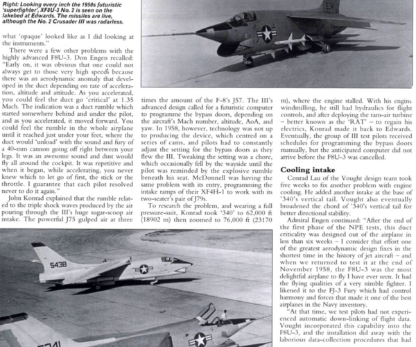
I highly doubt that MiG-19 and F100 are mixed compression. They both are more likely to be pitot normal shock by appearance and their low supersonic envelope. It would be very hard to achieve mixed compression over a range of Mach numbers without some variable intake geometry. Maybe the XF8U-3 with its forward swept cowl and large inlet bypass doors, but I’m just guessing based on the projected flight Mach numbers.
1679842044192.png

Sounds like they used the bypass doors to control the position of any internal shockwaves. Doesn't the F-22 do the same thing?

 
Yes, the F-22 does use inlet bypass doors to match inlet flow requirements to the engine flow characteristics. However, I don’t think the F-22 is a mixed compression inlet. More of an external compression oblique shock with fixed ramps on both the upper and inner inlet surfaces.

Supersonic inlets function in a stable manner over a relatively narrow range of airflow. Too little airflow and shock becomes unstable resulting in a pressure oscillation known as inlet “buzz”. Too much airflow and the shock gets swallowed (like mixed compression but uncontrolled) resulting in flow separation and heavy airflow distortion to the engine face. And the path between too much and too little tends to get narrower as the Mach number increases.

While I don’t know the full bypass door airflow strategy of the F-22, one of the considerations for a supercruise aircraft is how to slow down. On the F-15 and F-16, the engine control is electronically “locked up” at Mil power above 1.4M to keep sufficient airflow to prevent inlet buzz, ramping down to normal flight Idle at 0.85M. I read that the MiG-23 had a physical throttle stop that deployed to prevent the pilot from regarding the throttle below Mil while supersonic. If the F-22 is supercruising at 1.5M+ and you can’t get the power below Mil, how do you slow down? With the bypass doors, the pilot can reduce engine power and airflow below Mil to slow down while the bypass doors open to control the inlet airflow to remain above the minimum required for inlet stability.
 
Aren't the top bypass doors more to ease flow attachment at the critical part of the S-duct?
 
Aren't the top bypass doors more to ease flow attachment at the critical part of the S-duct?
Not that I am aware of. There are boundary layer bleed grids on the walls of the intake near the front, just after the ramp areas, and there used to be some boundary layer bleed doors on the front top surfaces above the inlet lip to increase this boundary layer bleed flow under high AOA conditions, but these were found to be unnecessary and were eliminated on the production aircraft. The bypass doors, located in the middle of the duct, only function is to increase inlet flow when needed for inlet stability.
 
I thought F-22 inlet is same as F-15, just fixed instead?

No, the F-15 uses an oblique shock structure that is only swept in one direction. The Inlet on the F-22 is an oblique shock that is swept in two directions. Also, while the F-14 and F-15 have moveable ramps for optimizing the shock structure, my understanding is that under operational use they usually flew with them fixed to reduce cost.
 
The splitter plate is only to separate the boundary layer from the inlet when the inlet is aft of the nose. Not needed when the inlet is the front of the aircraft.

Of course, the DSI inlet on the F-35 and J-20 directs the boundary layer around the inlet opening, so no splitter plate there either.
I thought the splitter plate also create oblique shock to slow down the supersonic air stream?. That how f-16/rafale make their external compression right?
The splitter plate can be angled or wedge shaped to create an oblique shock, like was used on the F-16/J79 demonstrator. But production F-16 inlets have a flat splitter and are normal shock designs. F-104 had a fixed half cone mounted on the splitter to create a semicircular oblique shock (slightly better recovery than a flat oblique), F-4 has a shallow wedge splitter with a moving back half to create a 2 oblique shock inlet for better pressure recovery at M2+.
So in short,
Rafale, F-35, F-16, F-100, Mig-19 are all internal compression inlet?
Eurofighter, F-15, F-14, F-104, Mirage, Mig-21 are external compression inlet
Mig-25, Mig-31, SR-71 are mixed compression?
SR-71 is mixed compression inlet

Don’t know about MiG-25/31. They appear to be external, multi-oblique with variable ramps, but I could be wrong.

All of the others are external compression, either normal shock (pitot) or oblique shock (ramps or cones, fixed or variable)
Correct me on this but why Mig-19 and F-100 are considered external compression?. Their compression are all inside the inlet right?. Nothing in front of the inlet I think, especially F-100
Capture.PNG
 
While theoretically possible, mixed compression in an open front duct is very difficult to achieve and maintain in real life. The adverse pressure gradient (I.e. higher pressure downstream) causes rapid thickening of the boundary layer and flow separation, and it is unlikely to operate correctly over a range of Mach numbers.

When you see an open tube as an intake, think normal shock at or in front of the opening, with subsonic flow inside the duct, no internal shock waves.
thank you, so to sum up no aircraft use internal compression inlet.
only SR-71 and possibly Mig-25 use mixed compression inlet
the rest are all external compression inlet?
XB-70 was mixed compression. Possibly XFU8-3 and MiG-25/31.

Other than those and the SR-71, everything else is external normal shock or oblique shock, to my knowledge.
 
There are quite a few air-breathing supersonic missiles with mixed compression intakes, but for manned aircraft, yeah, that's about it.
 
Looking for MCID inlet duct cross-sections beyond throat & capture ones that I seem to have...
 

Paper has high res variable ramp inlet WT model photos and drawings
 

Similar threads

Please donate to support the forum.

Back
Top Bottom