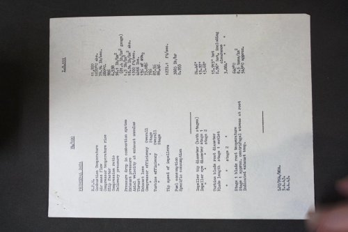
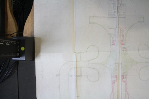
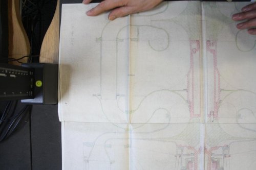
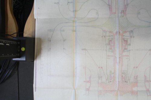
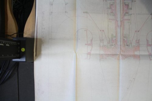
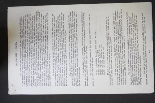
So while waiting for some early aviation docs to appear at Kew National Archives I started on early gas turbines.... I had often wondered what would follow the W2s at Power Jets and found there was a project for the W4/100; 2 centrifugal compressors, reverse flow combustion chambers and 2 stage axial turbine on a single shaft giving 4,000lb. The CC design seems to be a bit out-of-date but is probably to cut down length.
Dwg is a quick capture eventually I'll get a proper copy.
 

Attachments

  • 1273413AVIA_13_150_IMG_0002.JPG
    1273413AVIA_13_150_IMG_0002.JPG
    182 KB · Views: 328
  • 8401388AVIA_13_150_IMG_0004.JPG
    8401388AVIA_13_150_IMG_0004.JPG
    98.8 KB · Views: 324
  • 4518934AVIA_13_150_IMG_0023.JPG
    4518934AVIA_13_150_IMG_0023.JPG
    81.1 KB · Views: 316
  • 3988850AVIA_13_150_IMG_0024.JPG
    3988850AVIA_13_150_IMG_0024.JPG
    88.9 KB · Views: 312
  • 7804722AVIA_13_150_IMG_0025.JPG
    7804722AVIA_13_150_IMG_0025.JPG
    93.9 KB · Views: 306
  • 4264280AVIA_13_150_IMG_0026.JPG
    4264280AVIA_13_150_IMG_0026.JPG
    75.8 KB · Views: 108
tartle: excellent, thanks.

By any chance - could you enlighten us mere mortals with tales of early RR work on turbine air cooling? I actually asked the RR Heritage Trust Archives about whether they have material that could be possibly relevant to this, and although they do, they suggested I try the National Archives first - but I'd sure appreciate some pointers as to what to look for ;).

PS. still working on the z factors for German engines - apparently, misplaced some drawings during a move. Oh well...
 
OK ... I'll put up some stuff starting in a few days time.... in the technology stream we set up.
 
I have a question about the de Havilland Gyron Junior turbojet engine. Does anybody know what it's fuel consumption was? And it's weight? I'm trying to work out if substituting Bristol Olympus engines for the Gyron Juniors in the Bristol 188 would have resulted in a significantly better endurance to allow it to actually do the research it was intended to.
 
Try searching the Flight Magazine GT special editions... say 1957, 1962... you should find all you need there... saves someone else doing it.
 
from Wilkinson 1958/59

Olympus 200 : 0.8 lb/lbt/hr

Gyron Junior DGJ-10 : 0.9lb/lbt/hr

You also want Tony Buttler's article on the 188 in 'Wings of Fame' 18.

Chris
 
Thanks Chris. Very kind of you so only marginally better. I'll see if I find that article somewhere. I've often wondered why Bristol went on the 188 with a non-Bristol engine...
 
Bristol looked at fitting four and six Orpheus B. Or.12 (B. Or.3 fuel consumption listed in Wilkinson 58/59 as 1.06 lb/lbt/hr and the Orpheus 803 is listed as 1.08lb/lbt/hr in Wilkinson 64/65)

Chris
 
One of the key strategic problems was that the design of the 188 was wrong! Ted Talbot's book 'Concorde: a designer's life' describes the awful layout of the whole propulsion system. Talbot started as an aerodynamicist and ended his career as chief design engineer describes the problems of supersonic propulsion design and pints out the failures that were not revealed to the technical press. He points out that it is the basic design flaws that decide the 'failures' not the choice of engine...he sums it up on page 217:
"Many of the failures on these high-speed projects were associated with the power plants, the combinations of air inlet, engine and exhaust nozzle were so critical to good, efficient and safe operation of the aircraft as a whole. The Bristol 188 was no exception to the rule.
some truly some truly supersonic projects could only be counted as failures. This list would include the B-70.... the B-58 Hustler....the B-1......."
He then describes the problems with the SR-71 Blackbird that any normal service person would describe as a failure:
"It had remarkable but sensitive power plants. Should the aircraft depart from the design condition at high speed and cause an oscillation to occur in one or other engine, the rapid changes in thrust would cause the cockpit to move rapidly...There was a small elite band of intrepid aviators in america that belonged to 'The Split Helmet Club'"
Have a look at this for discussion of the complexity of problem... so changing 188's engine is not likely to improve anything ... a complete redesign was necessary.
 
K-Man: Bristol did not go with a non-Bristol engine. UK aero industry almost never spent its own money. We Pipers paid, so we called the tunes.

1953: Korea whimpering to stalemate, but we all presumed Sovs were recoiling the better to spring on Hanover. We were scheming "rockets" so we presumed deadly GAAPs were onway there too. Higher/faster bombers must succeed V-craft. RAE believed the (Meteor-esque) layout+stainless steel were way to go. MoS believed what their boffins said and invited bids, Avro 730 accepted. A proof-of-concept vehicle was clearly needed, to prove aerodynamics, fabrication-in-exotica, and supersonic intake design.

In 1954 MoS/RAE perceived themselves as scientists, "firms" as rude mechanicals, to do what their betters told them. MoS chose where to place Research jobs. Proper firms should be busy on proper products...and the Medium Bombers swamped them. So AWA+Bristol were idle and bored as airframe candidates; DH Engines ditto likewise. The cloned AWA+Bristol schemes were melded as T.188, much fabrication to go to AWA. Both would have built chunks of Avro 730. Intake design was the fief of RAE/Bedford (IIRC: Dr.Seddon, seen in MoS as the only man who understood such things). So also-ran teams were given the orphan job of building 5 T.188. MoS chose PS.50 to give it a Flying Test Bed - it was to have powered Blue Steel Mk.2 and SR.177. Drift. The chop came for the lot in 1957. Some US MWDP dribble-funds caused MoS to not chop T.188/PS.50, on the modest Aircraft Research budget...but unloved. Maybe it could have been made real (see artwork in Buttler's Hypersonics), but...>50,000ft in 1960s? Ask Gary Powers for his view.
 
> 50,000ft?
Isn't it true that the poor old E.E. Lightning on twin R-R Avon re-heat power could zoom past there easily,
- but were constrained by D. Sandys penny-pinching refusal to allow coordinated developments which
would deal with pilot physiological (pressure limited) & high Mach heat (shock cone/windscreen) limits?
 
It didn't need to zoom. There are accounts of Lightnings climbing on their own power above 60,000ft with ease. Two in the book, "English Electric Lightning: Britain's first and last supersonic fighter," by Tim McLelland.
 
Yes, ta, the E.E. Lightning did have a fairly impressive power-to-weight ratio/high Mach capability for its day,
& I've always wondered why it was not utilized in any record attempts like the Soviets & USAF/USN
did with their contemporary MiG 21 & F-104/F-4 types..
 
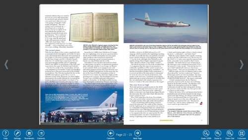
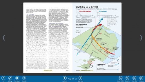
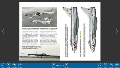
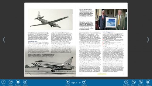
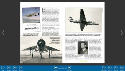
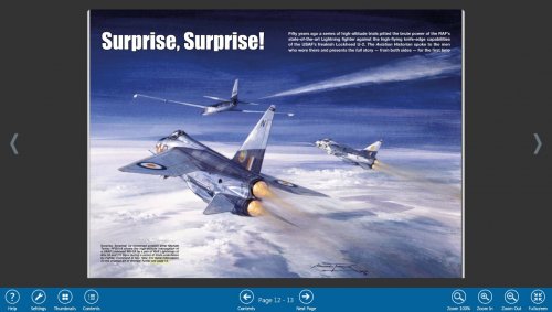
The magazine 'The Aviation Historian' has a free taster that includes Lightning details reproduced below...U2 can intercept aircraft at 60,000ft and Lightning speed! It is a high quality magazine.
 

Attachments

  • aviation history taster-06.jpg
    aviation history taster-06.jpg
    313.6 KB · Views: 147
  • aviation history taster-05.jpg
    aviation history taster-05.jpg
    293 KB · Views: 283
  • aviation history taster-04.jpg
    aviation history taster-04.jpg
    220.2 KB · Views: 273
  • aviation history taster-03.jpg
    aviation history taster-03.jpg
    291 KB · Views: 274
  • aviation history taster-02.jpg
    aviation history taster-02.jpg
    264 KB · Views: 293
  • aviation history taster-01.jpg
    aviation history taster-01.jpg
    232.4 KB · Views: 330
Most excellent stuff, thanks T,

& precisely the kind of thing that the jet-bent RAF with their poxy Meat-boxes,

- so embarrassingly -

could not do - to PRU Mk 19 Spits on similar exercises - post-war..
 
the combinations of air inlet, engine and exhaust nozzle were so critical
For the challenges to the Bristol188 which Ted Talbot says was aimed at M2 and then M3
we have the development story for the SR-71 intake, design point M3.2
http://www.enginehistory.org/Convention/2013/HowInletsWork8-19-13.pdf

There was a small elite band of intrepid aviators in america that belonged to 'The Split Helmet
There's also a look at trying to control the violent unstarts, at least up to M2.8 (SST research).
http://ntrs.nasa.gov/archive/nasa/casi.ntrs.nasa.gov/19750021055.pdf

For an insight into the nozzle challenges for the M2 goal we have the B-58 story.
The existing J79 nozzle (F-104) had to be more efficient at M2. This led to the 'low base drag nozzle' which also had improved internal expansion.
All told in SAE680295 "Variable-Geometry Exhaust Nozzles and their Effects on Airplane Performance".
 
More impressive than the U-2 intercepts...

"The target climbed from 65,000 to 80,000' while flying a 180 deg turn. He was surprised that the Lightning which carried out the next intercept overtook him in a descent through his altitude. His last run was into six figures and he was safe."
Ref Flt Lt Dave Roome based at Tengah in the late 1960's. "Lightning from the Cockpit" Peter Caygill

(RB-57F doing high altitude meteorological trials on turbulence prior to Concorde services to Singapore)
 
Can anyone tell me what 'DAMF' stands for?

Yes, I have seen the definitions on the net, but I doubt these would be used in a 1952 Armstrong Siddeley Motors paper on a turbojet.

The context is: 'An axial flow jet propulsion unit of 250 lb/sec DAMF.'

From the units, I'm assuming MF stands for 'mean flow' but probably wrong. There's no entry for 'DAMF' in the sainted Bill's 'Big Book of Aircraft Words' and the glossary in his book on Rolls-Royce Aero-engines says 'if you've bought this, you don't need a glossary'. There's nothing in the two Wilkinsons I have.

Thanks in advance.

Chris
 
Is it a steam turbine Chris? - Damf being the German for same - or 'wet' (ADI) thrust, perhaps..
 
That never crossed my mind. Could it be water injection?

All the catalogue entry says is:

'An axial flow jet propulsion unit of 250 lb/sec DAMF.'

Perhaps MF stands for Mass Flow?

Chris
 
When I was doing performance calculations using 3 ft long slide rules DAMF=Design Air Mass Flow
 
charleybarley said:
His last run was into six figures and he was safe."


IOW "Only above 100,000 feet could they not get him"?? Wow.


I have seen at least one YouTube vid of a Lightning letting loose with a Red Top or Firestreak (I can't tell for sure) - the curvature of the earth is clearly visible and the sky is more black than blue. So that's with what we assume is a fully-loaded, fully-dragged-up model, not one that's been stripped for a record. Impressive.
 
Kadija_Man said:
I have a question about the de Havilland Gyron Junior turbojet engine. Does anybody know what it's fuel consumption was? And it's weight? I'm trying to work out if substituting Bristol Olympus engines for the Gyron Juniors in the Bristol 188 would have resulted in a significantly better endurance to allow it to actually do the research it was intended to.


If not endurance, at least performance. (But with a different engine comes a different-sized nacelle, altered aerodynamics and weights, etc. etc. It ain't the same Bristol 188 by that point, and direct comparison becomes somewhat invalid.)


The Gyron Junior seems to have disappointed in both the platforms in which it's best known (Bristol 188 and Buccaneer S.1) as an underpowered, over-ravenous affair. One wonders what might have happened if F.155T had gone ahead and Armstrong-Whitworth's four-engined submission had won through.
 
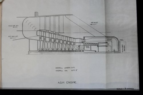
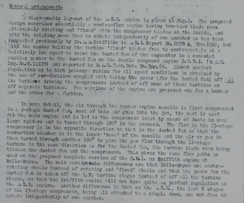
Whilst I am waiting for documents to appear after being selected from the 100 miles of shelves at the National Archives I idly bounce round Kew's weird and wonderful cataloguing system...aptly named Discovery. Today it was a toss up between the Fairey P. 24 installation dwg or Armstrong Siddeley's ASH GA and description. The GA is copied below and represents the Bomber engine version; see second attachment that describes the bomber and fighter version .....tbc
 

Attachments

  • 1751043Bulk_Order___IMG_0010.JPG
    1751043Bulk_Order___IMG_0010.JPG
    160.6 KB · Views: 401
  • GA-escription.jpg
    GA-escription.jpg
    186.8 KB · Views: 401
One rotor, one speed, one shaft and two bearings. What could possibly go wrong?
 
tartle said:
Whilst I am waiting for documents to appear after being selected from the 100 miles of shelves at the National Archives I idly bounce round Kew's weird and wonderful cataloguing system...aptly named Discovery. Today it was a toss up between the Fairey P. 24 installation dwg or Armstrong Siddeley's ASH GA and description. The GA is copied below and represents the Bomber engine version; see second attachment that describes the bomber and fighter version .....tbc

The turbine blades rotating about the same plane as the compressor blades -- stick the combusters between them and you have Frost's radial flow gas turbine.
 
Armstrong Siddeley P.151 proposal for Buccaneer

Roy Boot in his "From Spifire to Eurofighter" page 90, says this engine had "unusual characteristics in its variation of thrust with forward speed".

Can anyone explain this comment please?
 
charleybarley said:
Armstrong Siddeley P.151 proposal for Buccaneer

Roy Boot in his "From Spifire to Eurofighter" page 90, says this engine had "unusual characteristics in its variation of thrust with forward speed".

Can anyone explain this comment please?

Perhaps it was prone to surging or stalling and Boot was being droll?
 
Indeed - a somewhat unhelpfully cryptic remark..

Purely speculative, but the RN test pilots carrying out Buccaneer deck landing trials would surely have noted objectionable
surging characteristics at that end of the envelope..

May well apply to transonic flight regimes also, though..
 
He was referring to the Armstrong Siddeley P151 proposal which presumably was a paper engine.
 
As far as I can tell the P.151 project started as a version of the Sapphire Sa7 being developed for the thin wing Javelin... it then seems to moprh into a lightweight engine design... more digging needed!
 
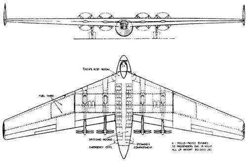
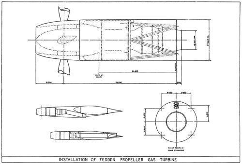
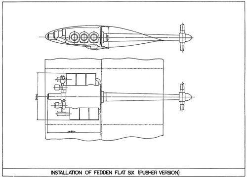
Some pictures showing aircraft and engines projects designed by the British engineer Sir Alfred Hubert Roy Fedden MBE, FRAeS.


Design for a thirty-two seater tail-less airliner – in other words a flying wing – published in Fedden’s 1944 paper The Future of Civil Aviation.
The 1,350 hp Propeller Turbine, or turboprop as this type of engine became known, illustrated in the Fedden brochure.
Fedden’s 4.6 litre sleeve valve Flat Six mounted within an aircraft’s wing with long drive shaft to the pusher propeller at the rear.


Source: The Race for Hitler's X-Planes: Britain's 1945 Mission To Capture Secret Luftwaffe Technology, by John Christopher, published by The History Press Ltd (2012)
 

Attachments

  • 00127.jpg
    00127.jpg
    27.1 KB · Views: 191
  • 00161.jpg
    00161.jpg
    24.6 KB · Views: 179
  • 00162.jpg
    00162.jpg
    21.9 KB · Views: 166
The B10 Betty layout drawing above can be read with the diagram in an earlier post ...
The flight engine F2/1 is shaown.. it went in the tail of a Lancaster.
The F.2/2 engine is also at MOSI, which can, and was combined with the F.3 Augmentor. Pictures below.
...and a Flight cutaway of the whole rear fan engine. There is another view of this cutaway with the addition of a sectional view and the aerofoil cross-sections on the Flight website.
Do you have any idea about when the MetroVick F.3 first run?
 
Just a noticed little titbit from BSP.
Armstrong P.151 and Bristol BE.30 are designs to (forgot title) request for engines of 8-9,000lb around 30" Diameter of cheaper cost than Sapphire or Avon.
Seems DH's Gyron Junior was developed to this as well.
This must have been late '53 to early '54.

Designs for subsonic NA.39, light fighter F177 and a supersonic twin engined fighter. .....

Seems someone had twigged the need for such engines that sit in a sweet spot for such aircraft.
 
In case you are wondering why I keep on about the W2/500..... when Stanley Hooker told Adrian Lombard to get on with the straight through engine to replace the Welland he took the best of the B26 (STx9) and the best features of the W2/500. Using as much of the B23 as possible Lombard's team came up with the B37 Derwent 1.
The improvements in performance of the W2 series came about through the interplay of several factors.
Compared with the W2B the W2/500 had a larger hub/tip ratio which permitted an increase in mass flow. Also fewer turbine blades of longer chord were used; the number used on the W2/500 was 54 each with a chord of 1.4 in., compared with 72 blades of 0.8 in chord. The change to fewer, larger blades was made on the recommendation of the RAE after the W2B suffered a number of turbine blade failures. The new blades were more resistant to the gas bending forces (lower stresses) and minor damage from solid particles passing through the annulus.
Metallurgy was key to development of a light, reliable engine. The advent of Whittle's gas turbine created the need for stronger, more durable alloys capable of high-temperature service When the WU was designed the best available material was Firth-Vickers 'Stayblade' and this was used for both disc and turbine blades. By the time the W1 was on the boards, F-V had produced an improved alloy- Rex 78 and this was used for the blades. But the first to answer the challeng was Leonard Bessemer Pfeil, who is credited with the development of Nimonic alloy 80 in 1941, at Henry Wiggin's research facility in Hereford. This alloy used for the blading was introduced into the later stages of the W2B development programme and in the W2?500 and /700 from the start.
The top two development issues that kept the W2B engineers awake at night were surging of the compressor and turbine blade failures. Some blade failures were a secondary consequence of a failure elsewhere. A piece of combustion chamber that had broken off could pass through the rear of the engine, notching blades on the way and this often led to blade failure. One series of failures was odd. Sometimes blades failed at the root sometimes half way up and occasionally close to the tip. Resonance would be expected to produce failures at the same place. Eventually it was realised failure was caused by a thermocouple mounted in the exhaust duct 3 inches downstream from the turbine. It was adjustable radially across the annulus and Whittle believed that there must be an upstream pressure field ahead of it of sufficient magnitude to interfere with the flow through the blades as they passed through it. It seems this was a correct diagnosis as the failure rate dropped dramatically after the thermocouple had been removed. [but it foretold of a similar problem that occurred during early development of the RB211 some 30 years later].
Another source of grief was the rubbing of turbine blade tips. The running clearance was intended to be small in order to minimise aerodynamic losses; unfortunately it is start-up and shut-down that determines the clearance. For instance at shutdown there is a sudden draught of cold air through the annulus which rapidly cools components of small mass like shroud rings, vanes, and blades but larger items, such as the disc cool more slowly. This means if the running clearances are too small the shroud ring could contract onto the blade tips on shutdown and at worst pick up the melted tip of the blades which would cause bending forces as blades passed over the material or as serious it could just lock up the rotating assembly causing much damage.
Sir, you wrote "the number (of blades) used on theW2/500 was 54 each with a chord of 1.4 in", but at drawings you applied, it is stated 1.2 in. Did I understand something wrong?
Do you know and could you tell me please, which W2 or later derivates engine variant could it be with 54 turbine blades matching all parameters like on your drawings, except the longer turbine blades (leading edge length ca. 3 in) with roots which are increasing its width slightly more at the front side than at the rear side of the disc?
Many thanks in advance!

Tartle hasn't been on the forum since 2014, so you are unlikely to get an answer from him.
Thank you very much!
 

Similar threads

Please donate to support the forum.

Back
Top Bottom