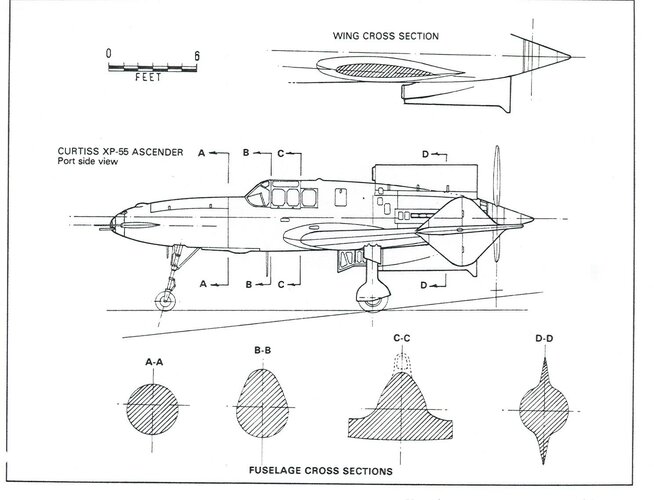
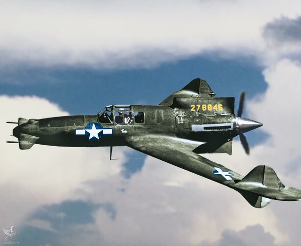
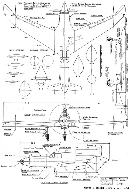
Actually, most of you are wrong on the aerodynamics/controls of the XP-55; as was I until I read the excellent books recently published on the subject. It was basically designed as a statically stable flying wing. The canard itself, being designed to weather vane when there weren't any pitch control inputs. However, when a pitch control input was used it would move the control surface and also cause the vehicle to be unstable in pitch. So they they were basically trying to have a statically stable platform that was dynamically unstable in pitch. This was so they could have the best of both worlds; stable in cruise flight, unstable while maneuvering. They were trying to design the F-16 before they had the technology to handle it. Now, the Hurricane was unstable as well, but it was quite marginal in that regard. It seems they were going for greater instability for greater maneuverability with the XP-55.

Unfortunately, they were unable to overcome the excess friction/lag in the control system, which caused the nose to porpoise in pitch. They also had issues with the small size of the canard, in the sense that it didn't have the control power to get the aircraft out of a deep stall. It was far more advanced then I had originally considered.
 
XP-55 suffered numerous balance and control problems.
It was essentially a flying wing with a small trimming canard on the nose.

After test pilots XP-24B complained about poor yaw stability, engineers added fixed fins both above and below the engine cowling. Then they moved rudders farther outboard, which also moved them slightly farther aft. Still, neither of these "fixes" moved the lateral centre of area far enough aft to significantly improve yaw stability. XP-24B still had a very short tail moment arm. Poor yaw control was one of the reasons they lost a prototype in a flat spin.
Rutan solved his problem by moving his vertical fins and rudders all the way out to the wing tips, the farthest aft possible. Rutan also used his vertical fins as end-plates/Witcolm winglets to reduce wing tip vortices.
Flat spins and un-recoverable stalls are often also caused by centre of gravity too far aft of the centre of lift.
Curtiss engineers tried to move the centre of lift farther aft by enlarging wing tips and sweeping them even farther aft.
The primary reason for XP-54's swept wings was to improve balance. For comparison, look at the contemporary Japanese Luke, Shinden and Senden pushers. They all mount their engines between main wing spars to move the centre of balance forward. However, this configuration required lengthy/problematic drive shafts to spin the propeller aft of the wings' trailing edge.
Unfortunately, Curtiss engineers did not understand how wing sweep affects stall characteristics. Most airplanes stall wing root first. This helps maintain roll/aileron control part way into the stall. Unfortunately, on swept wings, stall turbulence quickly migrates to the outer wing panels, reducing (desired) nose down tendencies. Rutan solved this problem with vortilons. Vortilons are small wing fences on the underside that resemble engine pylons on jet airliners. Military swept wing airplanes use a variety of fences (MiG 15), fins and dogs tooth leading (F-4 Phantom) edge modifications to limit turbulent migration.
 
Last edited:

Attachments

  • XP-55.jpg
    XP-55.jpg
    162 KB · Views: 181
  • plan.jpg
    plan.jpg
    106.4 KB · Views: 141
  • side compare.jpg
    side compare.jpg
    277.3 KB · Views: 133
  • front comparison.jpg
    front comparison.jpg
    158.6 KB · Views: 141
  • curtiss-wright-cw24.jpg
    curtiss-wright-cw24.jpg
    20.8 KB · Views: 122
Last edited:

Attachments

  • ascender4.jpg
    ascender4.jpg
    235.6 KB · Views: 128
  • JH1001.jpg
    JH1001.jpg
    254.4 KB · Views: 139
Last edited:
Just to clarify, Burt Rutan solved stability problems with his canards by moving the centre of gravity well forward thus requiring the canard to provide a significant amount of lift. Just look at the flat-bottomed, cambered airfoil used on Long-Eze canards.

Also note how Long-Eze clusters variable loads like fuel, passengers and baggage at the Centre of Gravity/wing root leading edge. The primary reason many of Rutan’s canards have LERX, strakes, etc. is because they are a convenient place to stow fuel near the C. of G.
Also remember than most of Rutan’s canards are optimized for cruise efficiency. That mission limits their STOL and aerobatic performance.

And to clarify my point about stalls in swept wing airplanes. Some Long Ezes suffered from stalled wing tips (nose down pitching moment) while wing roots were still lifting (nose up pitching moment).
After a Velocity kitplane (4-seater clone of Long Eze) “mushed” (stable stall) into a lake, they fitted vortilons to all future kits. Fortunately, the “mushing” Velocity descended so slowly that the pilot survived landing in a lake!
 
Last edited:
Just to clarify, Burt Rutan solved stability problems with his canards by moving the centre of gravity well forward thus requiring the canard to provide a significant amount of lift. Just look at the flat-bottomed, cambered airfoil used on Long-Eze canards.

Also note how Long-Eze clusters variable loads like fuel, passengers and baggage at the Centre of Gravity/wing root leading edge. The primary reason many of Rutan’s canards have LERX, strakes, etc. is because they are a convenient place to stow fuel near the C. of G.
Also remember than most of Rutan’s canards are optimized for cruise efficiency. That mission limits their STOL and aerobatic performance.

And to clarify my point about stalls in swept wing airplanes. Some Long Ezes suffered from stalled wing tips (nose down pitching moment) while wing roots were still lifting (nose up pitching moment).
After a Velocity kitplane (4-seater cline of Long Eze) “mushed” (stage stall) into a lake, they fitted vortilons to all future kits. Fortunately, the “mushing” Velocity descended so slowly that the pilot survived landing in a lake!

That's all fine and well, but hasn't anything to do with the XP-55. The XP-55 was not a canard aircraft in that it's forward control surface did not carry any of the aircraft load in stable flight as canard aircraft do. The forward control surface was not for trimming, it was only for maneuvering control; dynamic stability, or instability, in this case. If the pilot wasn't pitching the aircraft, the only contribution from the forward control surface was weight and drag. This was neither like the J7W1, SS4, or the Rutan designs.

Yes, Curtiss swept the wings for the same reason Jack Northrop's wings were swept; stability. Because the XP-55 was a flying wing, only with a fuselage and a pitch control surface for maneuvering on the nose.

Unfortunately, there was too much friction in the control system, leading to lag responses and porpoising. The aircraft also had drag and cooling problems. They really needed the help of the NAA engineers in that regard.
 
Dear sundog,
I am not trying to disagree with you.

Rather I am trying to explain stability and control problems with WW2 vintage canards like Ascender and the Japaneses Shinden.
Those problems were not solved until decades later and even Burt Rutan admits that he "lucked out" on some of his canard configurations.

Are you saying that Ascender's canard functioned more like the "rhino rudder" on Rutan's Defiant? .. in that it free-floated until the pilot pressed on a rudder pedal?
 
Yes, Curtiss Ascender did not use an extension shaft, but it also suffered handlingproblems because the center-of-gravity being too far aft.
Curtiss XP-55


On 27 November, 1939 the USAAC announced the competition ‘Request for data R-40C’ for a very high performance fighter that should be equal to the new European models, to be built in 1941.

The Air Corps Interceptor Pursuit Specification XC-622, required:

Single-engine, single-seater with a top speed of at least 425 mph at 20,000 ft, sufficient to attack or leave combat area at will.

Seven minutes to climb to 20,000 ft.

Good pilot visibility

Four guns armament

Enough maneuverability

One and half hours endurance

The 2,000 hp, 24 cylinder ‘H’, liquid-cooled Pratt & Whitney X-1800-A3G engine was initially proposed.

Curtiss proposed the P-248-01design, an Allison powered CW-21 Demon and the CW-24, an unorthodox tailless-canard fighter, with 45 degrees swept-back wings and pusher propeller.

Around fifty projects were presented by nine different companies. By the end of 1940 six of them had been selected: Vultee (XP-54), Curtiss Wright CW-24 (XP-55), Northrop (XP-56), MacDonnell (Mod 1), Republic (AP-12) and Bell (Mod 13).

The first three qualified ones were never mass manufactured because they were of a too radical pusher design, making a failure of the whole $ 6,000,000 programme.

Throughout aviation history there have been designs of the canard or ‘tail-first’ types as an alternative to the conventional ‘engine-first’ configuration. However, in spite of the creativity of designers, manufacturers have systematically left aside the mass production of such solutions. When the second generation of fighters designed during the Second World War started to experiment serious aerodynamic problems, due to the transonic flux, they made several tries to solve them using the canard configuration eliminating airscrew slipstream effects on aircraft drag.

With this new configuration the designers tried to elude the problem of compressibility buffeting by installing the wing behind the center of gravity.

The British firm Miles built and fly tested the M.35 and M.39B prototypes as technological demonstrators of the M.39 bomber.

The German Henschel designed the heavy fighter named P.75 that should be propelled by a DB 613 A/B coupled engine and which mass production was abandoned in favor of the Dornier Do 335.

Several prototypes of canard fighters were built in Italy and USA.

The canard formula had many advantages for the design of fighters; the armament could be grouped around the nose without any hindrance by either the engine or the propeller and it was very easily accessible for maintenance, ground visibility was considerably improved and it was easier to install a tricycle type undercarriage.

The nose foreplanes had been found to serve the purpose of improving take-off performance and low speed control.

The engine, located behind the pilot, acted as protection against the rear impacts and, in the event of a fire, flames did not go to the cockpit as used to happen with the classical designs. Besides, being joined to the main spar meant less weight and stronger structural sturdiness.

In combat, an enemy pilot not familiar with the new configuration could easily mistake the direction to which the canard fighter moved during the deflection aiming. Same tactic is used by some tropical fishes that have a spot in the shape of a false eye near the tail to confuse their predators.

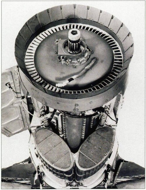
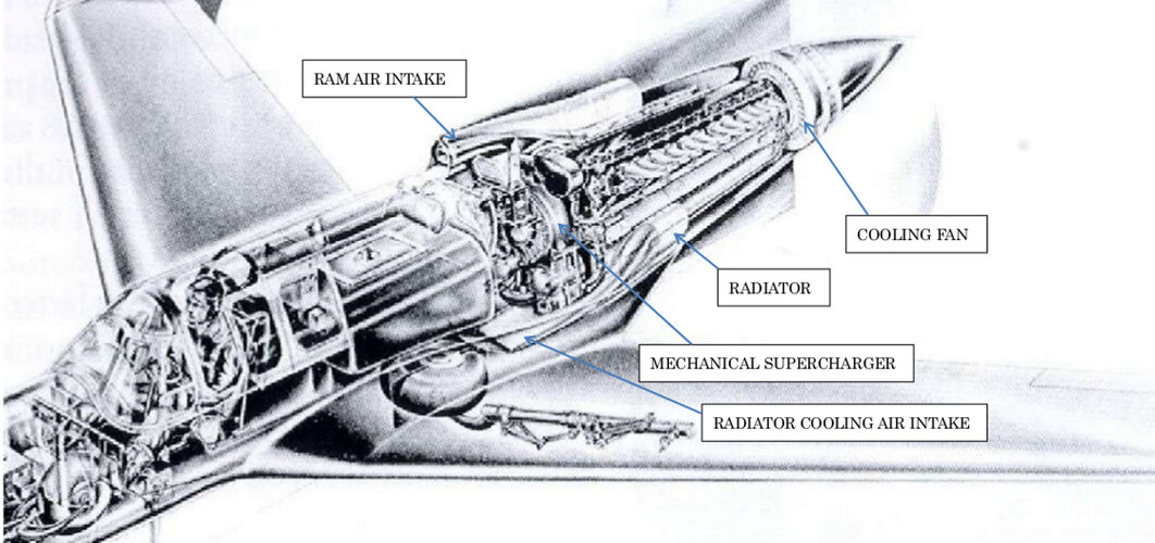
Only two inconveniencies marred all the advantages: the difficulty to refrigerate the engine and the baling out, due to the position of the pusher airscrews. At a time when ejector seats did not yet exist, the solution was to install an explosive device to detach the propeller in case of emergency.

Early in 1939 the Italians built the Ambrosini S.S.4 a canard prototype fighter powered by one 960 hp Isotta Fraschini Asso XI RC.40 engine. The airplane was destroyed in 1941 due to a problem of vibration of the engine mount and the project was cancelled.

On 22 June 1940 the USAAC signed a contract for preliminary development of the Curtiss CW-24 and construction of a wind tunnel model, under the designation XP-55.

Such a radical configuration required the construction of the CW-24B, a flying testbed to prove the design viability.

On 21 December 1941 the CW-24B made its first flight, at Muroc Dry Lake test center, powered by a 275 hp Menasco C-6S-5 engine.

Despite the strong security measures, intelligence services of the IJN obtained enough information about the project to believe that it was the successor of the Curtiss P-40 fighter. Early in 1943 Lieutenant Commander Masaoki Tsuruno, of the First Naval Air Technical Arsenal, proposed the construction of the canard fighter 18-shi-Otsu J7W Shinden based on the information obtained on the XP-55.

In fact, the definitive Curtiss XP-55 version was not selected by USAAC for production and only three prototypes were built, two of which were destroyed in accidents.

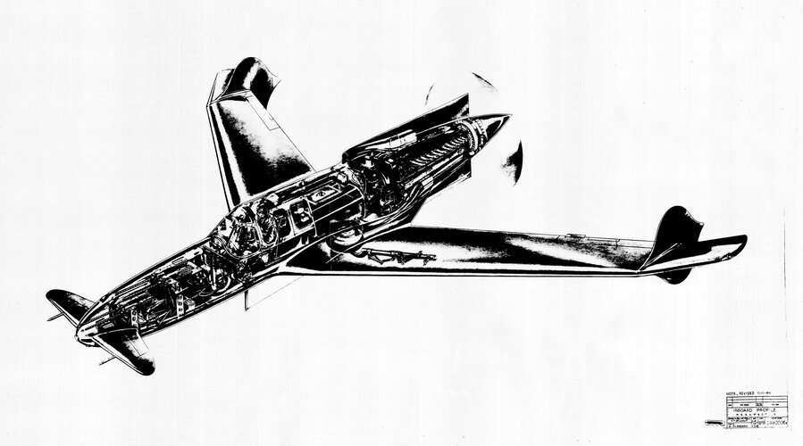
On 10 July 1942 the USAAF ordered three prototypes, the 42-78845 flew on 13 July 1943 powered by one 1,425 Allison V-1710-95, V-12, liquid-cooled engine, with mechanical supercharger, driving a three-bladed (jettisonable) pusher airscrew.

The aircraft was fitted with laminar-flow swept wings angled back 45 degrees and tricycle undercarriage.

USAAF was unimpressed with the 377 mph top speed reached with the Allison engine versus the 507 mph promised with the X-1800 cancelled in October 1940.

The first prototype showed excessive take off run, dangerous stall behaviour, poor longitudinal stability, low-speed handling problems and engine overheating.

On 15 November 1943 the plane was lost, in an inverted spin, when the engine failed.

The second prototype 42-78846 flew on 9 January 1944 suffering from ‘no-warning before stalling’ phenomena. To improve the stall characteristics the nose elevator and the aileron tabs were modified.

The third prototype 42-78847 was flown on 25 April 1944, fitted with wing extensions and modified nose elevator and armed with four 0.50 cal nose mounted machine guns.

On 27 May 1945 the aircraft crashed when the pilot attempted a barrel roll.

Americans were not lucky with the Curtiss XP-55, after four years of flight testing they have not achieved an airplane sufficiently stable to take part in combat operations.

Although it was less sensible to the compressibility buffeting than conventional airplanes, thanks to a NACA 0015 type wing profile, it was also too heavy and slower than the P-47 and P-51 in service.


Curtiss XP-55 technical data

Power plant: one 1,425 hp Allison V-1710-95, V-12, liquid-cooled engine, with mechanical supercharger, driving a three-bladed (jettisonable) pusher airscrew.

Wingspan: 44.5 ft (13.56 m), length: 29.6 ft (9.02 m), height: 10 ft (3.05 m), wing area: 235 sq. ft (21.83 sq. m), max speed: 390 mph (630 kph), max weight: 7,330 lbs (3,324 kg), service ceiling: 34,600 ft (10,550 m), armament: six 0.50 cal M2 heavy machine guns.

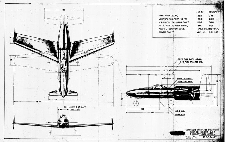
Before cancelling the project, the Curtiss firm proposed the production of a jet version based on the original P 249-C project, known in the specialized literature as P 286-17 or CW 24-C. It would have been propelled by a centrifugal De Havilland H-1B Goblin turbojet with a fuel tank of 1,059 lt., located behind the pilot, and armed with four 0.50 cal M2 machine guns. Its mass production was abandoned in favor of the Lockheed P-80.

On 31 March 1945 Curtiss proposed two versions of the P-304 a single-jet, medium-range fighter specifically designed to overcome the effects of compressibility, using the accumulated knowledge from the XP-55 programme.


Curtiss CW 24-C technical data

Power plant: de Havilland H-1B Goblin turbojet with 2,460 lbs (1,114 kgf) static thrust.

Wingspan: 39.36 ft (12 m), length: 28.10 ft (8.57 m), height: 9 ft (2.74 m), armament: four 0.50 cal M2 heavy machine guns.


Curtiss P-304-4 technical data

Power plant: one General Electric TG-180 turbojet with 4,000 lbs (1,814 kgf) static thrust.

Wingspan: 40 ft (12.2 m), length: 33.8 ft (10.3 m), height: 9.5 ft (2.9 m), wing area: 240 sq. ft (21.6 sq. m), max weight: 14,470 lbs (6,564 kg), armament: four 0.50 cal M2 heavy machine guns.


Curtiss P-304-5 technical data

Power plant: one General Electric TG-180 turbojet with 4,000 lbs (1,814 kgf) static thrust.

Wingspan: 40 ft (12.2 m), length: 33.4 ft (10.21 m), height: 9.5 ft (2.9 m), wing area: 240 sq. ft (21.6 sq .m), estimated max speed: 622 mph (1,001 kph) at 10,000 ft, estimated climb rate: 5,530 ft/min, max weight: 14,170 lbs (6,428 kg), combat radius: 500 miles (805 km), armament: four 0.50 cal M2 heavy machine guns.
 
Some photos I took a few months ago:

ac9b1623-bc74-45ad-a526-c24839d520bc-jpeg.801864

604836a9-c882-4f3a-90d1-49aa5becfd56-jpeg.801865
1dd61a2e-59e9-48c9-aff3-c5a454ca8a54-jpeg.801866
bffd0619-8c8d-4caa-863a-fc7f329591da-jpeg.801868
 
Looks like NACA2415 but not sure, also in the Model Airplane News from July 1945 shows a laminar flow airfoil.
Alex
 

"On June 22nd, 1940, Curtiss received a contract for a powered wind tunnel model, engineering data, and an optional prototype. A 1/4 scale model with two different wing designs was ready by November 2nd. The first wing design was a conventional airfoil, while the other was a new laminar design that would reduce drag. Both of them had the severe sweep that was retained to the final stage.During testing from November 1940 to January 1941, the vertical rudders were added to the wingtips to control yaw. The USAAF was unimpressed with the model's performance but gave the go-ahead to continue work with the laminar wing. It was during this time that the Pratt & Whitney X-1800-A3G was canceled, forcing a change in the planned engine to the venerable Allision V-1710-95"
 
Last edited:
Just for giggles and kicks, is there a configuration that might make the design viable?

Different engine and wing etc?
 
No, with the technology available at that time.
During the 1960s, SAAB figured out that they needed to load the Viggen's canard much heavier to attain decent stability and control. So the Curtiss Ascender would have needed its center-of-gravity farther forward so that it leaned heavily on a lifting canard.
 

Similar threads

Please donate to support the forum.

Back
Top Bottom