Сокрушитель бомбардировщиков. Проект тяжелого дальнего истребителя-перехватчика и истребителя сопровождения Curtiss-Wright XP-71. США - Альтернативная История

alternathistory.ru
"Bomber Destroyer. Curtiss-Wright XP-71 Heavy Long-Range Interceptor and Escort Fighter Project USA
Before the United States entered World War II, Americans viewed the war from a detached perspective. Americans closely followed the development (and deterioration) of the situation in Europe, where surprise bombing attacks were paralyzing both the armed forces and the population. Nazi Germany and the Axis powers had conquered Poland, Norway, the Netherlands, and finally France to create a real threat of attack on American soil after the fall of Britain. These studies stimulated the development of heavy fighters designed to counter the threat of enemy bomber formations, and one such design submitted to the U.S. Army Air Corps was the Curtiss-Wright XP-71, a two-seat, long-range heavy fighter/interceptor concept.
The primary mission of the new aircraft was to intercept bomber formations, scattering their formations with artillery fire while evading defensive fire and enemy escort fighters. A secondary mission was to be to escort friendly long-range bombers when the tide of hostilities turned against the invaders. The aircraft being developed had to have the necessary speed, firepower, and range to meet the combat missions assigned to it. In accordance with practice adopted in the late 1930s, two prototypes of the aircraft, internally designated Model CW-29 and officially designated XP-71 by the U.S. Army Air Forces, were ordered by the Army Air Corps. The contract was signed on October 28, 1941, several months before the Japanese surprise attack on Pearl Harbor, Hawaii.
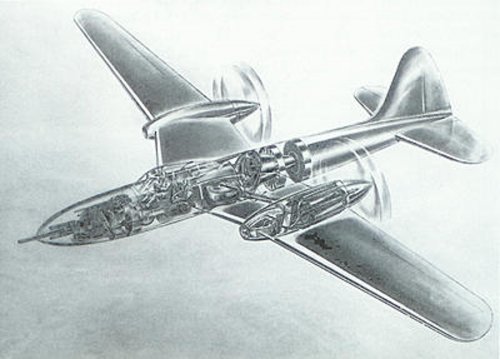
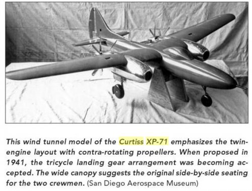
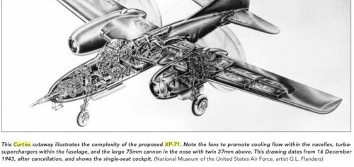
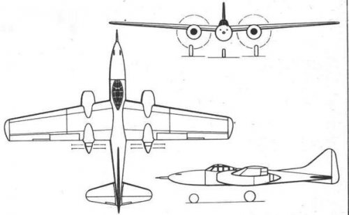
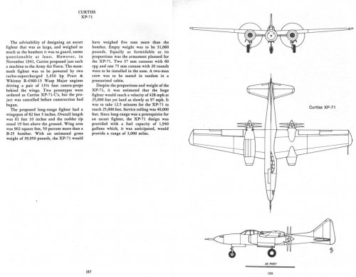
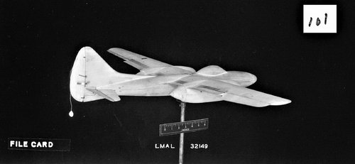
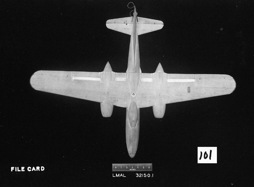
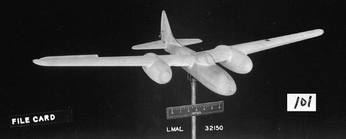
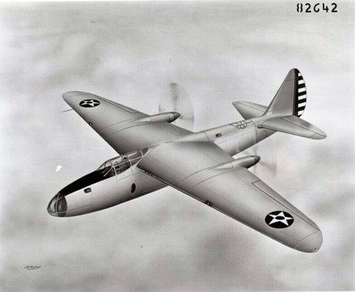
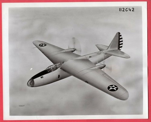
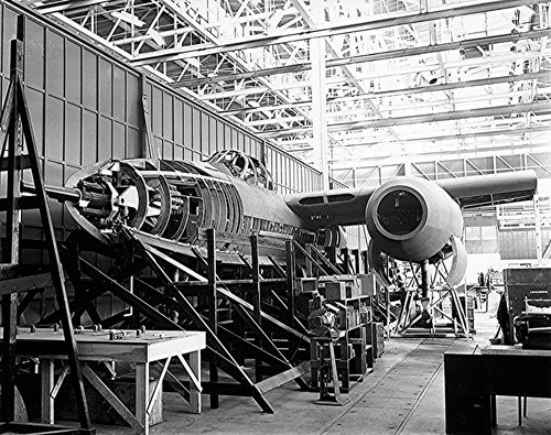
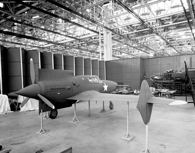
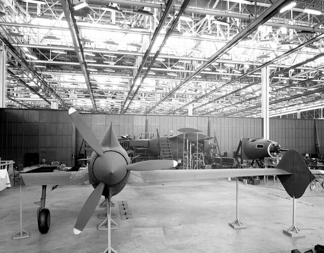
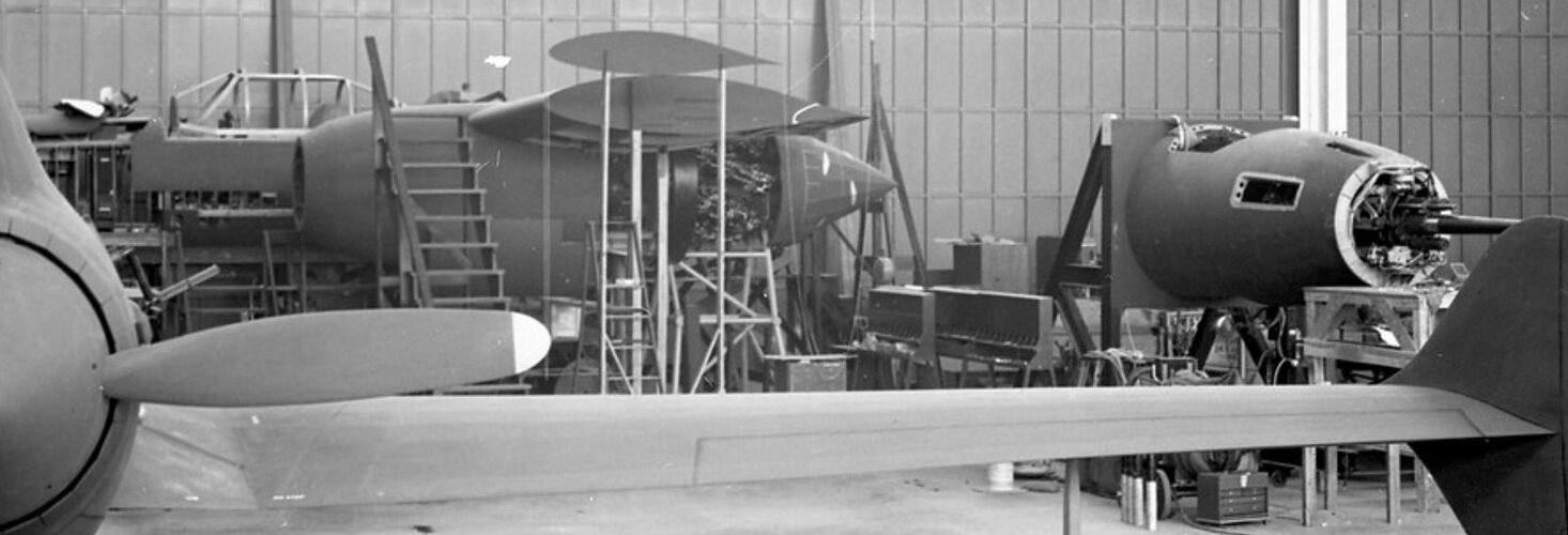
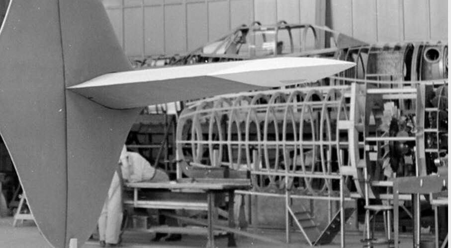
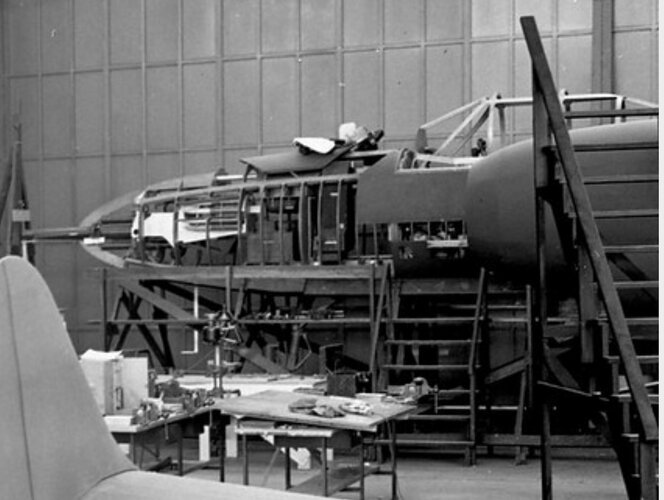
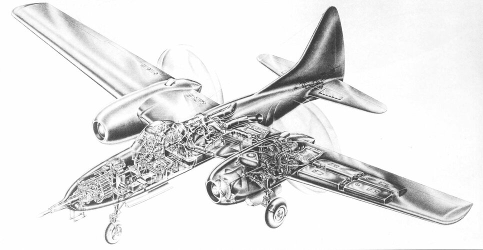
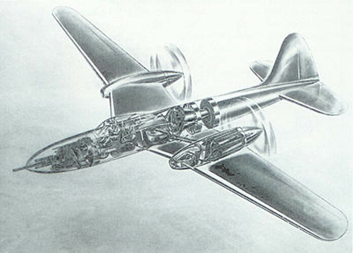
By November 1942, the XP-71 mockup had been completed and reviewed by the commission, and an interesting design solution was adopted to transform the XP-71 into a heavy single-seat fighter. This solution allowed for maximum use of the internal space to accommodate avionics, fuel, and electronics, which simultaneously increased the pilot's workload during flight. The tasks set before the developers led to an increase in the overall dimensions of the fighter, which in this indicator was comparable to medium bombers: the wingspan was 82 feet 3 inches (25.07 m), the length was 61 feet 10 inches (18.85 m), and the height was 19 feet 0 inches (5.79 m). Curtiss-Wright engineers chose a traditional layout in which the fuselage made up most of the aircraft's overall length. The high wing was connected to the middle section of the fuselage. Each wing console was crossed by an engine nacelle, which extended beyond both the leading and trailing edges. The crew cabin was located just ahead of the leading edge of the wing and, thanks to a teardrop-shaped canopy, provided excellent visibility forward, to the sides and to the rear. The cabin was located well behind the nose cone, which was to house the powerful cannon armament. Behind the wing, the fuselage narrowed to the tail end, which was crowned by a large single-fin tail unit with a low-set horizontal tail and rounded tips. The tricycle landing gear of the aircraft had a nose strut, which facilitated control during taxiing on the ground and provided the necessary clearance for the rotation of the propeller blades. The first flight was tentatively scheduled for June 1944.
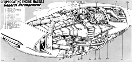
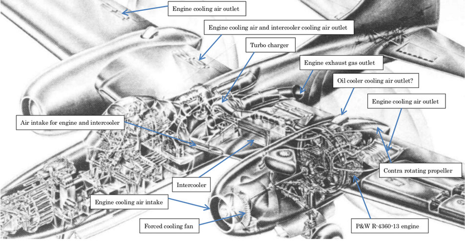
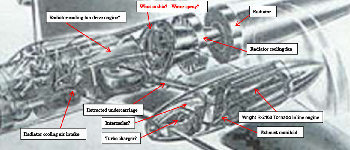
The XP-71 powerplant was to consist of two large Pratt & Whitney R-4360-13 Wasp Major air-cooled radial piston engines, each producing 3,450 hp, coupled to General Electric turbochargers. The total power output of the powerplant was 6,900 hp, which required a rigid engine frame design and large propeller blades to provide optimum thrust. The engines were to be equipped with Hamilton Standard pusher contra-rotating propellers with a diameter of 13 ft 6 in (4.1 m), i.e. the propellers were to be mounted on the trailing edge of the wing, and not in front of the leading edge of the wing, which is typical for many other aircraft. Undoubtedly, this technical solution was one of the most unique in the XP-71 design. The twin-engine powerplant was to give the aircraft a maximum speed of 430 mph (692 km/h) with a range of up to 3,000 miles. The XP-71's service ceiling was to be 40,000 feet (12,192 m), which required the aircraft to be fitted with a fully pressurized cockpit.
The cornerstone of the "bomber fighter" design was its armament, which was based on a 75mm cannon, the barrel of which protruded from the nose of the fuselage. It was supplemented by two 37mm cannons mounted side by side. The armament allowed the XP-71 to quickly and effectively destroy any bomber in service with the Axis air forces. The 75mm cannon was fed by an automatic device that provided 20 rounds, while the 37mm cannon was provided with 60 rounds each. The ammunition supply was quite limited and required careful aiming and short bursts from the pilot to achieve good effect.
Work on the aircraft at Curtiss-Wright continued into 1943, and realizing its technical advantages was proving to be a greater challenge for engineers than had been initially anticipated. During testing in February 1943, the nose gun placement proved problematic, and the weapons systems used revealed their shortcomings. Added to these were the changing nature of the war. By 1943, there was no longer any question of Axis bomber armadas attacking the continental United States: Germany had lost the Battle of Britain and, bogged down in the Eastern Front, could no longer spare the resources for an intercontinental bomber fleet, Italy was suffering one defeat after another in Africa, and Japan's advance in the Pacific had been halted. Under these conditions, there was no longer a need for a heavy long-range interceptor fighter, and the lighter and more maneuverable single-seat fighters North American P-51 and Republic P-47 Thunderbolt were able to cope with the role of escort fighter for Allied long-range bombers.
In October 1943, the XP-71 heavy long-range interceptor fighter program, however promising, was officially canceled. For a time, the Army Air Corps considered turning the XP-71 into a long-range, high-altitude reconnaissance aircraft, but that proposal died. The other branches of the armed forces showed no interest in the aircraft, and the XP-71 joined many other American efforts to create the ideal aircraft for combat missions during World War II."

