Cooling fans + air-cooled radials & cooling

@sienar

Still you didn’t get that thing with the reference area. The Cd value in David’s paper is referred to the wetted area and because the Spitfire Mark IX has more wetted area than the FW190, it has a lower cd value despite having a higher absolute drag. If David would have used the frontal area as reference, the Cd value of the FW-190 with its bulkier fuselage would have been lower. Despite that, what really matters is the absolute drag (zero lift drag) and no matter which Cd you are using, the FW190 A has a lower drag than the Spitfire IX.

I guess, David didn’t include a rotating fan in his calculation, if so, the drag of the FW190 would be even lower, because the fan is pushing out the air with power from the engine.

I would recommend you, not to read too many complicate books about aerodynamic before you didn’t understand the fundamentels:

“Notice that the area (A) given in the drag equation is given as a reference area. The drag depends directly on the size of the body. Since we are dealing with aerodynamic forces, the dependence can be characterized by some area. But which area do we choose? If we think of drag as being caused by friction between the air and the body, a logical choice would be the total surface area of the body. If we think of drag as being a resistance to the flow, a more logical choice would be the frontal area of the body that is perpendicular to the flow direction. And finally, if we want to compare with the lift coefficient, we should use the same wing area used to derive the lift coefficient. Since the drag coefficient is usually determined experimentally by measuring drag and the area and then performing the division to produce the coefficient, we are free to use any area that can be easily measured. If we choose the wing area, rather than the cross-sectional area, the computed coefficient will have a different value. But the drag is the same, and the coefficients are related by the ratio of the areas. In practice, drag coefficients are reported based on a wide variety of object areas. In the report, the aerodynamicist must specify the area used; when using the data, the reader may have to convert the drag coefficient using the ratio of the areas." (https://www.grc.nasa.gov/www/k-12/airplane/drageq.html)
Frontal area wasn't used because frontal area isn't all that important in aircraft that are as slow as WW2-era, prop driven fighters. It wasn't even particularly important in the few jet fighters that saw service in WW2.

As to the rotating fan, one would need to determine the fan's efficiency and the pressure drop within the engine to determine what -- if any -- thrust would occur. One would also need to account for the power required to drive the fan. It's not that unlikely that the fan would be a net detriment to airframe efficiency in many flight regimes.
 
@sienar

Still you didn’t get that thing with the reference area. The Cd value in David’s paper is referred to the wetted area and because the Spitfire Mark IX has more wetted area than the FW190, it has a lower cd value despite having a higher absolute drag. If David would have used the frontal area as reference, the Cd value of the FW-190 with its bulkier fuselage would have been lower. Despite that, what really matters is the absolute drag (zero lift drag) and no matter which Cd you are using, the FW190 A has a lower drag than the Spitfire IX.

I guess, David didn’t include a rotating fan in his calculation, if so, the drag of the FW190 would be even lower, because the fan is pushing out the air with power from the engine.

I would recommend you, not to read too many complicate books about aerodynamic before you didn’t understand the fundamentels:

“Notice that the area (A) given in the drag equation is given as a reference area. The drag depends directly on the size of the body. Since we are dealing with aerodynamic forces, the dependence can be characterized by some area. But which area do we choose? If we think of drag as being caused by friction between the air and the body, a logical choice would be the total surface area of the body. If we think of drag as being a resistance to the flow, a more logical choice would be the frontal area of the body that is perpendicular to the flow direction. And finally, if we want to compare with the lift coefficient, we should use the same wing area used to derive the lift coefficient. Since the drag coefficient is usually determined experimentally by measuring drag and the area and then performing the division to produce the coefficient, we are free to use any area that can be easily measured. If we choose the wing area, rather than the cross-sectional area, the computed coefficient will have a different value. But the drag is the same, and the coefficients are related by the ratio of the areas. In practice, drag coefficients are reported based on a wide variety of object areas. In the report, the aerodynamicist must specify the area used; when using the data, the reader may have to convert the drag coefficient using the ratio of the areas." (https://www.grc.nasa.gov/www/k-12/airplane/drageq.html)
For aircraft as slow as WW2 fighters, frontal area is simply not that important; the major source of drag for a reasonably designed fighter would be skin friction. Of course, there are other sources of drag, including cooling (which, according to SJ Miley, is not significantly different between radials and liquid-cooled engines), cavities, e.g., no landing gear doors, leakage (gear doors, cockpit ventilation, etc), antennas (wires normal to airflow have huge drag), guns, bomb shackles, etc.
 
Its not about the importance frontal areas or not, its about the FW190 A and its drag. I linked a video as (secondary) source which showed, that the FW190 A had indeed a lower drag than the Spitfire mark IX. Until the FW190 air cooled fighter engines were associated with high drag, so that the development focused very much on liquid cooled fighter engines.

After the video was claimed to be not trustworthy, I linked the primary source which fully complies with the video.

There are more than one Cd value and drag is not directly proportional to the Cd value, you always have to multiply it with the reference area.
 
You had two separate aerodynamists correct you in that thread but you didn't believe them. Since Lednicer is quoted in a youtube video, maybe you'll take his word for it. That is why you should contact him, because you most definitely do not understand the things you think you do.

His email is posted on uiuc airfoil usage and his website - hardly secret or non-public.
If you think about the YB49 / B47 thread, PaulMM (admin) confirmed me in an a personal E-Mail that I was right and he deleted his single sided comment, take a look on it by yourself:


I’m sure David Lednicer will be thankfull for spamming his e-mail account...
 
Last edited:
It has already been mentioned here the reason, but I will elaborate a bit. You have to get a certain amount of air through the cooling fins. There are a couple of ways to do this, but it is more than just having an air source and an exit for that air. The air source needs to have a high total pressure that then gets drawn through the baffles and then the cooling fins. You can have a large opening to have that air push itself through, but then you are going to have unacceptable losses at cruise speed. If you then make the inlet sized for cruise, then it will have issues in low speed high power conditions such as takeoff and climb.

Cowl flaps help this by causing a pressure loss just aft of the flap itself. It does this by actually being "inefficient" and having flow losses. This then reduces the pressure at the exit of the cooling air, and creates a larger pressure differential across the cylinders drawing more air through.

If you were only to open a slot, this would not change the pressure differential across the cylinders and would not increase the cooling flow despite the larger area unless the initial area was not sufficient causing an internal flow loss in the cooling system and you would reduce this by opening the area. If this were the case, though, that would likely mean that you would get inlet spillage around the cowl entrance and you would be dealing with those aero issues there.

The cooling fan itself, is extra weight that is not always needed and will always be taking some engine power to work.

As is in almost every engineering problem, though, you need an entire set of tools to find the best compromise for the situation you are designing for. Engineering is not about creating the best thing, it is about creating something that finds the right combination of compromises to achieve your end goal.
Well stated.
 
Did any engines use a mix?
If the liquid cooling system was down…they could throttle back to air cooling.

Any water cooled radials?

BMW 803; if you also want to include inline-radial engines like the Jumo 222 and Wright Tornado, you will find several.
 
Despite the advantages of cooling with lower speeds, the cooling fan was potentially the more effective solution than the standart cowlings:

"It showed that the drag power expended by the airplane to propel an internal flow system was always significantly greater than the "pumping power" required to force the internal flow through the cowling" (https://history.nasa.gov/SP-445/ch5-3.htm)

This is of course only true if the fan drive war efficient enough to keep the losses below the difference between drag power and pumping power.
 
Hi Nicknick,

This is of course only true if the fan drive war efficient enough to keep the losses below the difference between drag power and pumping power.

A case where it didn't work out so well was the Porsche PFM 3200, at least if you follow this article:


However, that might have been entirely attributable to poor design in detail. I'm not sure how accurate the estimates in the article are, but it seems to indicate that external drag also played a role in the Porsche-powered Mooney being less than a world beater ...

Regards,

Henning (HoHun)
 
I don’t think, that high rpm are the best solution for aircraft engines and the traditional design of existing engines is very well suited for their application. Despite that, the article is very single sided, electronic fuel injection and ignition is much more efficient and reliable than any mechanical system which has to be manually operated by a hobby pilot. The Continental FADEC Diesel engines are the most reliable engines in their program and FADEC engines are nowadays also available for their gasoline engines (e.g. in the Tecnam Traveller). Single lever control is the way to go and Porsche was pioneering this for general aviation.

The Porsche Mooney is a sleek looking plane which definitely has no bulbous cowling, the opposite is true. With a stroke of only 74 mm, the engine width will surely not be wider than any 200 PS Lycomming/Continental, despite having overhead cams. The lower speed of the Porsche powered Mooney might as well be the result of the charge air cooler in combination with higher weight and something else (Propeller, restriction in engine rpm, whatever).

The turbo charged version was capable of 180 kw (245 PS) continuously up to 16.000 ft with a dry weight of 200 kg, that’s not bad at all:

https://www2.lba.de/data/bb/Motoren/en_4609_01.pdf

https://www.continental.aero/uploadedFiles/Content/Engines/Gasoline_engines/300AvGas-SpecSheet.pdf

Since the power consumption of the fan is already included in the 180 kW continuously it is hard to believe, that the additional internal cooling flow losses of the Porsche powered plane would have been higher than in standard designs.
 
You had two separate aerodynamists correct you in that thread but you didn't believe them. Since Lednicer is quoted in a youtube video, maybe you'll take his word for it. That is why you should contact him, because you most definitely do not understand the things you think you do.

His email is posted on uiuc airfoil usage and his website - hardly secret or non-public.

Of course, I could be lurking in this forum...

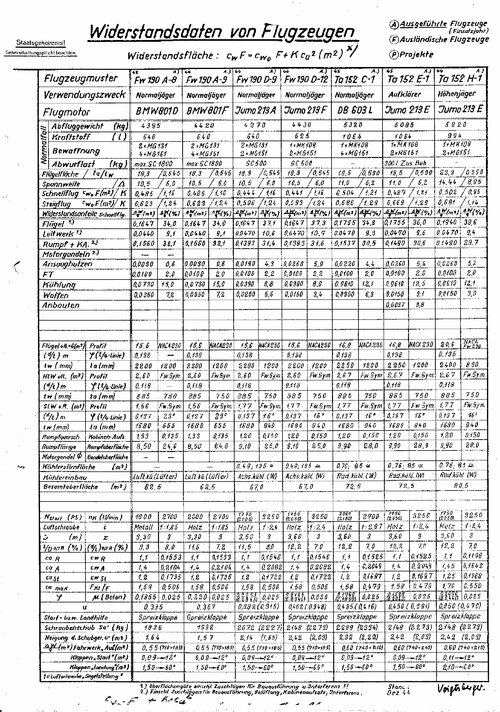
My Fw 190 drag value (if I remember right) is that reported by Focke Wulf:
Fw 190 Drag Table.jpg
 

Similar threads

Please donate to support the forum.

Back
Top Bottom