Scott Kenny
ACCESS: USAP
- Joined
- 15 May 2023
- Messages
- 11,427
- Reaction score
- 13,935
Doesn't mean it was a good idea.Although really complicated, the idea did exist.
Doesn't mean it was a good idea.Although really complicated, the idea did exist.
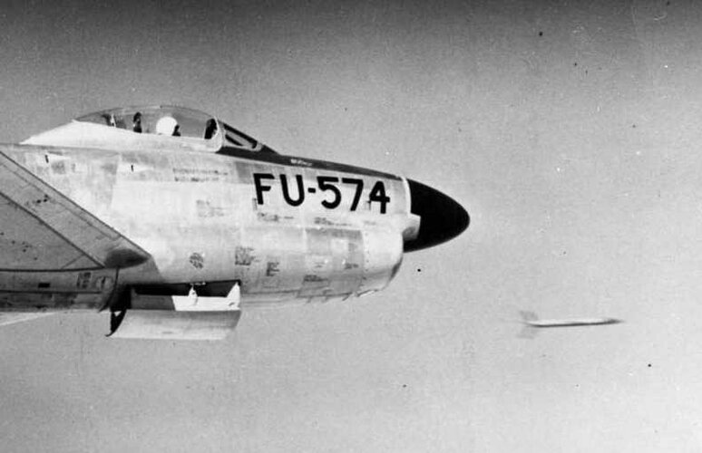
F2Y-2???Anybody know where exactly the production SeaDart was going to carry its missiles?
Seems that only build-in rocket & gun armament was developed to any significant extent, before the program got terminated. I suppose, if Sea Dart actually entered service, they would got over-wing pylons for Sidewinders (like on British Lighting). Or (less probable) some kind of "missile tubes" with caps, build into hull.Anybody know where exactly the production SeaDart was going to carry its missiles?
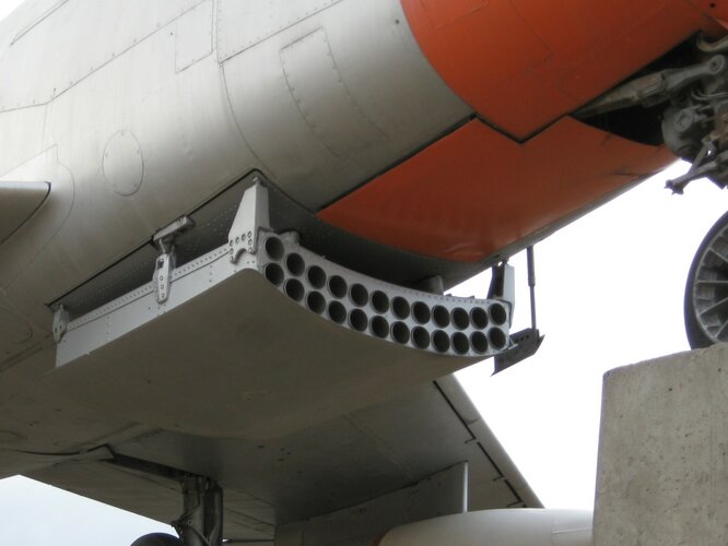
Those are rockets; unguided folding-fin rockets, carried internally in build-in launch tubes.F2Y-2???
In some aircraft of that time, the two types were used simultaneously.Those are rockets; unguided folding-fin rockets, carried internally in build-in launch tubes.
Yes, but not from same launchers. Missiles are bigger, and required locking on target - either by themselves (i.e. their seeker must stuck out of plane for some time - like Sidewinder), or by fire control system (which required sophisticated radar and computer on plane - like Falcon).In some aircraft of that time, the two types were used simultaneously.
The problem with this aircraft is that there is nowhere to install the rockets (retractable or not) where the gases ejected when firing are not ingested by the air intakes. The only thing that could be done is to install them on the wings as in the British Jaguar or Lighting jet fighters.Yes, but not from same launchers. Missiles are bigger, and required locking on target - either by themselves (i.e. their seeker must stuck out of plane for some time - like Sidewinder), or by fire control system (which required sophisticated radar and computer on plane - like Falcon).
With all respect, but F-86D Sabre Dog have rocket launcher installed right below the air intake:The problem with this aircraft is that there is nowhere to install the rockets (retractable or not) where the gases ejected when firing are not ingested by the air intakes. The only thing that could be done is to install them on the wings as in the British Jaguar or Lighting jet fighters.


2 NACA RM E55E25
INTRODUCTION
Compressor stall and flame - out in turbojet engines have occurred on
numerous occasions when rocket missiles and cannon were fired at high
altitudes . The U.S . Air Force has reported stall and flame - out in the
F-86 and the F-94C, and the U.S . Navy in the Cutlass and the Fury. In
addition, the British have encountered this problem in their Swift and
Hunter airplanes . Obviously, then, the problem is rather general in
nature and is not one that is peculiar to anyone aircraft or to any
one engine .
One factor that obviously contributes to these engine difficulties
is the ingestion of rocket and cannon-shell exhaust gases into the engines.
The extent to which rocket exhaust can enter the engine air intakes
is illustrated in figure 1, which shows a photograph of an F-94C
aircraft approximately 0.7 second after firing rockets. The exhaust
smoke and vapor trails from the rockets envelop a large part of the airplane
and can enter the air intakes in appreciable quantities.
The following engine- inlet effects will occur during the firing of
armament :
(1) Increased inlet temperature
(2) Changed inlet pressure
(3) Distorted inlet-pressure and temperature profiles
(4) Entry of combustibles into engine
(5) Reduced oxygen content in gases entering engine
The object of this paper is to examine each of these ~hings that oc cur
when armament is fired and to show by analys is and by experimental
data whi ch of these items are important and how each affects engine performance
. Deductions are made of the causes of the compressor stall and
flame - out that have been encountered in flight . Finally, some remedial
measures are suggested .
EFFECTS AT ENGINE INLET
Rocket Firing
Analysis . - The magnitude of the temperature and pressure effects
at t he engine inlet cannot be obtained directly from existing data . Several
sets of data on jet spreading and mixing must be considered together.
NACA RM E55E25 3
For the 2 . 75-inch air-to- air rocket (fig. 2), the combustionchamber
pressure is 1100 pounds per square inch and the temperature is
45000 R. The design exit Mach number is 2 .7 and the exit static pressure
is 42 pounds per square inch. Since this pressure is considerably above
ambient pressure at altitude, the jet will expand greatly upon leaving
the nozzle. The amount of initial expansion can be obtained directly
from existing data (ref. 1), but the amount of mixing farther downstream
cannot. Experimental data on jet mixing are presented in reference 2.
These mixing data were obtained with low velocities for both the jet and
the stream; in addition, the two streams had equal temperatures and static
pressures. These conditions are in marked contrast to the high velocities
and the temperature and pressure differences noted for the rocket.
Nevertheless, an estimate of rocket-jet spreading can be obtained by
adding the results of reference 2 to the supersonic expansion, as indicated
by the diagram in figure 2.
Results of a typical calculation are shown in figure 3. The stream
Mach number relative to the launching station is taken to be 0.9 and the
altitude 45,000 feet. At the time shown (about 0.3 sec after firing),
the rocket is 60 feet from the launcher and is moving away at a speed of
400 feet per second. Contours of temperature are shown for the exhaust
from a single rocket; these temperatures are expressed as the difference
between the temperature at various locations and the ambient temperature.
If the position of the inlet relative to the launcher is known, temperature
increments at the engine inlet can be estimated. For example,
consider an inlet 1 foot in diameter whose centerline is spaced 1.5 feet
from that of the rocket. If the inlet is in the plane of the launcher,
the average temperature of the entering stream would be about 2000 F
above ambient. The temperature increment will vary from 2600 F at the
inner face to 1400 F at the outer, as indicated by the inset in figure 3.
If the calculations represented in figure 3 are repeated for other
lengths of time after firing, the temperature profiles at any station
can be obtained as a function of time. Temperature variations at the
launcher station are shown in figure 4 . Variations in total pressure are
also shown in figure 4, and these pressures are expressed as the difference
between the local pressure and the free - stream total pressure divided
by the free-stream total pressure . ...
