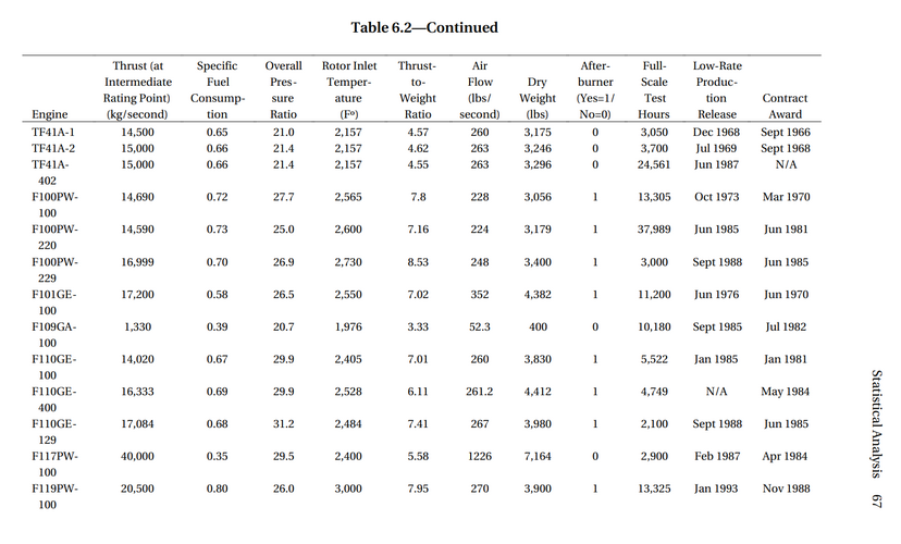
Comparison of modern fighter turbofans

Unless the 200kg is the weight of the control system.

I'm not very convinced. The weight difference between the F100-PW-100 and the -220 with the digital electronic engine control (DEEC) is roughly 200 lbs (90 kg); of course, there are also other mechanical differences between the two in order to greatly improve the reliability of the latter, but I doubt that a more modern engine control unit would weigh over twice as much.
The weight difference between the F100-100 and -220 was primarily due to the durability improvements in the rotating components and a bearing support to increase the depot inspection interval from 1800 TAC cycles to 4000 TAC cycles while maintaining full performance over that interval. The weight change from the original UFC/EEC/ vane type Main Fuel Pump to the DEEC / MFC/AFC/ gear type MFP was minimal.
The -100 engine had also gained weight before the -220 was produced. The -200 engine for the F-16 incorporated the proximate splitter in the intermediate case aft of the fan (stall / stagnation fix), containment bands around the fan duct (later replaced by thicker LPT cases), the Backup Control (BUC) on the -200, and some of the augmentor nozzle segments and seals had been beefed up for longer life. If I remember correctly, the actual -220 weight gain from the fielded -100 was around 150 lbs, and 125 lbs from the -200.
 
I think it's also interesting to note the architecture of the YF120 (GE37). It has a 2-stage fan, 5-stage compressor, and single stage low pressure and high pressure turbines. For an engine of its class, this appears to have the fewest stages thus far, which makes me curious about the OPR. The EMD F120 would have aimed at producing the same thrust at lower operating temperatures. I believe the EJ200 and the izdeliye 30 has the next fewest stages, with three fan, six five compressor, and single LPT and HPT stages. Interestingly, Piotr Butowski published the stage architecture of the izdeliye 30 as early as 2013.

I would also be curious about the lineage between the YF120 and the current XA100, but it's quite possible that there is very little; not only is there potentially an institutional gap due to a generational difference between most of those working on the respective project, they are also fundamentally different variable/adaptive cycle architectures. According to an Aviation Week article in 2015 describing GE's AETD developments that would eventually lead to the XA100, the adaptive design being tested at the time had a three-stage adaptive fan and a compressor derived from the CFM LEAP's 10-stage compressor. However, I doubt that the current XA100 design, which completed detailed design in 2019, would have that many compressor stages. I believe P&W's adaptive fan design for the XA101 is also three-stage.
 
Last edited:
I think it's also interesting to note the architecture of the YF120 (GE37). It has a 2-stage fan, 5-stage compressor, and single stage low pressure and high pressure turbines. For an engine of its class, this appears to have the fewest stages thus far, which makes me curious about the OPR. The EMD F120 would have aimed at producing the same thrust at lower operating temperatures. I believe the EJ200 and the izdeliye 30 has the next fewest stages, with three fan, six compressor, and single LPT and HPT stages. Interestingly, Piotr Butowski published the stage architecture of the izdeliye 30 as early as 2013.

I would also be curious about the lineage between the YF120 and the current XA100, but it's quite possible that there is very little; not only is there potentially an institutional gap due to a generational difference between most of those working on the respective project, they are also fundamentally different variable/adaptive cycle architectures. According to an Aviation Week article in 2015 describing GE's AETD developments that would eventually lead to the XA100, the adaptive design being tested at the time had a three-stage adaptive fan and a compressor derived from the CFM LEAP's 10-stage compressor. However, I doubt that the current XA100 design, which completed detailed design in 2019, would have that many compressor stages. I believe P&W's adaptive fan design for the XA101 is also three-stage.
The F119 is also 3 stage fan, 6 stage HPC, and single stage high and low turbines.

F135 has the same architecture as F119, except for a larger 3 stage fan and a 2 stage LPT. I’ve heard that the two stage LPT was necessary to extract sufficient power for the lift fan on the F-35B, and is on the other variants only for commonality.

By the way, the EJ200 high compressor is only 5 stages. This data sheet from MTU has a lot of good data on this engine https://www.mtu.de/fileadmin/EN/7_News_Media/2_Media/Brochures/Engines/EJ200.pdf
Sorry, I meant to say that both the EJ200 and izdeliye 30 have five compressor stages, that was a brain fart on my part. The F119 and the M88 have six stages.

It’s rather interesting to note that the M88 has a lower published OPR, BPR, but higher TIT than the EJ200, despite the latter being considered a more optimized for supersonic performance. The M88’s lower OPR and BPR is a bit puzzling, considering that they’re both of roughly the same vintage, and I don’t think supersonic performance was as large of a design driver as the EJ200.
 
M88 needed more stages than EJ200 for slightly less OPR as it is a bit less modern in design. M88-2 is somewhere between F404 and EJ200 at least in earlier models. Thrust to weight is 8.52:1 where EJ200 is 9:1+.

The initial M88-1 demonstrator TET was 1700K and M88-2 is 1850K. 1800K was given earlier for EJ200, but recently no value is generally given so not sure if that's still correct. Other EJ200 figures are approximate ("thrust class") not exact so I'd say they are likely very close.

Bypass ratio of the M88-2 is 0.3. EJ200 settled on 0.4. Not vastly different. F404 is 0.34.

The EJ200 was designed to have built in 15% thrust growth capability margin that hasn't been used to my knowledge - with priority given to increased reliability instead.
 
SFC figures show slight dry thrust SFC advantage to EJ200 (consistent with higher BPR) with parity in afterburner.

M88-2 - 0.782/1.663
EJ200 - 0.74/1.66
 
EJ200 cycle was optimised for lower fuel consumption in afterburner for better supersonic performance, not supercruise in particular.

Tornado F3's RB.199 SFC was 2.5 with afterburning. EJ200's 1.66 was a dramatic improvement.
 
SNECMA stuck waaay too long with Atar 9. Early atempts to get out of it in the 50's were crushed or didn't worked - Vulcain, Super Atar... and then they missed the turbofan train, hanged out with Pratt for a decade and ultimately beat them at their own TF30 game - the 306E was a fine engine. For nothing, just like the M45.
From these two come the M53 which suffered a bit the comparison with contemporary engines of the 70's.
The CFM56 smart trick granted them access to a F101 core on a civilian disguise and it helped too.
The M88 was the one engine where they really caught up with RR and the Americans.
 
I think it's also interesting to note the architecture of the YF120 (GE37). It has a 2-stage fan, 5-stage compressor, and single stage low pressure and high pressure turbines. For an engine of its class, this appears to have the fewest stages thus far, which makes me curious about the OPR. The EMD F120 would have aimed at producing the same thrust at lower operating temperatures. I believe the EJ200 and the izdeliye 30 has the next fewest stages, with three fan, six five compressor, and single LPT and HPT stages. Interestingly, Piotr Butowski published the stage architecture of the izdeliye 30 as early as 2013.

I would also be curious about the lineage between the YF120 and the current XA100, but it's quite possible that there is very little; not only is there potentially an institutional gap due to a generational difference between most of those working on the respective project, they are also fundamentally different variable/adaptive cycle architectures. According to an Aviation Week article in 2015 describing GE's AETD developments that would eventually lead to the XA100, the adaptive design being tested at the time had a three-stage adaptive fan and a compressor derived from the CFM LEAP's 10-stage compressor. However, I doubt that the current XA100 design, which completed detailed design in 2019, would have that many compressor stages. I believe P&W's adaptive fan design for the XA101 is also three-stage.
YF120 had an unusual architecture related to its variable design. It had a 3 stage fan, but the first two were on the low rotor, and the 3rd stage was at the front end of the high rotor. The true high compressor was only 4 stages. When in high bypass mode, part of the second and part of the third stage discharged into the fan duct. In low bypass, the 2nd stage bypass was closed off and only the 3rd stage bypassed into the fan flow.

The low stage count resulted in the low OPR, but that gives a lower compressor discharge temperature which lets them push more fuel into the combustor before reaching turbine temperature limits. Good for supersonic thrust, but it was definitely a thirstier engine than the YF119.
 
YF120 had an unusual architecture related to its variable design. It had a 3 stage fan, but the first two were on the low rotor, and the 3rd stage was at the front end of the high rotor. The true high compressor was only 4 stages. When in high bypass mode, part of the second and part of the third stage discharged into the fan duct. In low bypass, the 2nd stage bypass was closed off and only the 3rd stage bypassed into the fan flow.
True, and I do recall seeing a diagram of the F120’s VABI architecture from Aronstein’s ATF book; it showed two bypass channels, one in front of and one behind the third core-driven fan stage. The variable bypass was pressure driven for simplicity and reliability, although according to YF-23 test pilot Paul Metz, the YF120 exhibited noticeable throttle input lag. During aerial refueling, they would set one engine at a constant throttle setting and use the other to control speed.

I do think that the F120 would have been slightly larger in at least one of the cardinal dimensions than the F119; if you compare the EMD F-23A schematics, DP-232 with the F120 has a slight notch/serration in the fuselage trailing edge geometry while DP-231 with the F119 did not, which I presume is because of the former’s larger dimensions. DP-232 also has slightly longer overall length. DP-232 probably wouldn’t represent a production F-23/F120, as I would imagine that they would eliminate that notch when refining the design when going into CDR, but it’s interesting to see that the airframe designs were slightly different due to the engines.
 
Last edited:

Attachments

  • 29153E71-82C5-44F9-8464-9C33FB91F7B0.jpeg
    29153E71-82C5-44F9-8464-9C33FB91F7B0.jpeg
    31.3 KB · Views: 131
RAND paper "Military Jet Engine Acquisition Technology Basics and Cost-Estimating Methodology" could also be helpful.
The F119 figures there are quite off and may correspond to the YF119 built and tested during Dem/Val. The EMD/production F119 is considerably larger and heavier, while also producing more thrust, than what those numbers suggest.

EDIT: The commonly stated weights for the YF119 and YF120 may be without the divergent nozzle section (station 8 to 9), which are considered aircraft contractor-furnished equipment per Aronstein & Hirschberg.
 
Last edited:
The F119 figures there are quite off and may correspond to the YF119 built and tested during Dem/Val. The EMD/production F119 is considerably larger and heavier, while also producing more thrust, than what those numbers suggest.
That would make more sense.

Discussing YF119->F119 changes, Walter N. Bylciw – then P&W’s Vice President for F119 programs in an interview with Aviation Week said that rig tests of the new fan in Q4 of 1990 showed “20% more thrust than the ATF engine full-scale development specifications require.” April 29, 1991 issue, pg. 24. YF119 original spec was "30,000 lbf. class" with earlier optimistic 50,000 lbs. gross weight ATF requirement, changed to "35,000 lbf class" in late 1987.

Unaugmented thrust also rose by 10% YF119->F119. Discussed by David C. Aronstein, Michael J. Hirschberg, Albert C. Piccirillo, “Advanced Tactical Fighter To F-22 Raptor – Origins of the 21st Century Air Dominance Fighter”, pg. 227.

Overall, Bill Sweetman's 1998 book, "F-22 Raptor" states F119's intermediate rating is likely 25,000 to 27,000 lbf. and afterburning of up to 39,000 lbf. on pg. 40.
 
Publicly available TO-00-85-20 offers information on the true size of the F119 and F135.

F119 is 196 inches long and approximately 5,000 lbs, while the F135-100 is 6,422 lbs (just under the not-to-exceed weight of about 6,500 lbs from an early Pratt product card) and the F135-600 is 7,260 lbs. @overscan (PaulMM), update the first post?

It's unsurprising that these engines are quite massive and heavy, as the F119 core (which the F135 largely uses) is heavily built in order to withstand elevated temperatures from inlet heating at supercruise conditions while maintaining RPM for dry thrust as well as acceptable durability. Interestingly, the core airflow of the F135 is a bit undersized for the F-35 inlet that was revised in 2005, while the F136 which began development post-SDD sized its core appropriately.

https://webapp1.dlib.indiana.edu/vi...cgi/5346616/FID2182/TO_Files/00-85-20_022.pdf (this link works sporadically)
 
Huh so no where near a TWR of 11 for the F135 and the F119 stucks at 7.8 given 5000lbs/39000lbf?? Its inlet diameter seems to be around 98cm.


1717518678282.png

2x F414 derivatives would've been much better for the F-35.
 
Yes, and that would broadly align with a Japanese ATLA/IHI report for their development of the XF9-1, where they list the F119 as having inlet diameter in the 1.0 meter range, and their goal with the XF9 was to achieve F119-level technology and performance while downscaled to F110-size which has an inlet diameter of about 0.9 meter.

Furthermore, the approximate weight of 5,000 lbs for the F119 also aligns with P&W's statement that the F135 weighs about 1,500 lbs more than the F119. Cascading weight growth of the JSF was partially why the F135 evolved to be quite a bit bigger than than the F119; I believe that at one point the JSF was meant to use the same engine as the F-22, and part of the weight increase and redesign of the F-35 was driven by the larger engine requirement, i.e. a positive feedback loop of sorts. Perhaps an Air Force/Marine Corps CALF without the Navy requirements (2x2,000 lbs internal air-to-surface ordnance) may have avoided some of that weight growth. Alternately, an Air Force/Navy aircraft may have worked with 2xF414. But in any case, that's water under the bridge at this point.

That being said, I think the significance of thrust-to-weight ratio is a bit misleading, since it doesn't take into account certain operating requirements and parameters. I'm sure you can make a considerably lighter engine than the F119 while having the same thrust class and materials technology, but such a design may not be able to structurally maintain RPM at the higher temperatures from supercruise conditions, or it may have to drastically sacrifice durability. Tradeoffs like these aren't properly captured by thrust-to-weight ratio.
 
Last edited:
Are those weights and ratios including fluids? If so, that'll contribute, double digit T/W ratios generally seem to be based on dry weight.

Also, both engines are disadvantaged in certain ways by the rectangular nozzle in the F119 (non-optimal structural shape) and relatively high BPR in the F135 (almost 2x higher than in other contemporary fighter turbofans). Hot section RCS reduction measures might also have an impact. Furthermore, they're both large engines, which typically affects T/W ratio somewhat negatively (for a given cycle, thrust scales with massflow i.e. area, weight with volume) - probably not that huge a factor though.
 
I believe the weights for U.S. engines are typically for a configuration that's ready for installation, so I’d imagine that it would include fluids and oils (POLs). I doubt that the exclusion of fluids would push the thrust-to-weight ratios much higher though.

As a side note, the size of the F119 is also why I’m a bit skeptical of the claim that the izdeliye 30 (meant to roughly match the AL-41F-1 footprint) can significantly exceed it in mass flow.
 
The izdeliye 30 has been formally designated the AL-51F-1 last year.

It would be interesting to see the characteristics of the WS-10 family some time in the future (likely quite a while). In many ways, they're unlicensed distant cousins of the F110, both having cores based on the F101/CFM56.
 
Likely some influence from the AL-31F as well (example of a complete, relatively modern engine rather than just a core) on earlier models, but China seems to be moving reasonably well to indigenous developments.
 
the YF120 exhibited noticeable throttle input lag. During aerial refueling, they would set one engine at a constant throttle setting and use the other to control speed.
He did say that it would be an easy software fix had it been selected though.
 
The izdeliye 30 has been formally designated the AL-51F-1 last year.

It would be interesting to see the characteristics of the WS-10 family some time in the future (likely quite a while). In many ways, they're unlicensed distant cousins of the F110, both having cores based on the F101/CFM56.

Likely some influence from the AL-31F as well (example of a complete, relatively modern engine rather than just a core) on earlier models, but China seems to be moving reasonably well to indigenous developments.
Paper on WS-10A in J-11. Thrust curves included.
 

Attachments

  • 202302222139156325464.pdf
    410.4 KB · Views: 15
The lifespan of American engines, at least for P&W, isn’t really measured in hours, but total accumulated cycles (TAC), and it corresponds to engine usage rather than strictly time. For instance, I think spooling up from idle to full afterburner would constitute some cycle quantity, and a long flight with little throttle variation may have fewer cycles than a short flight with lots of throttle variations. Literature has suggested that the F119 has a lifespan of 8,650 TAC and depot overhaul at 4,325 TAC. I’m not sure if all US engines follow this method of measurement.
All US military engines since the F100 count cycles, not hours. You got the story why earlier.

CFM56 also counts cycles for most of their maintenance requirements. Not sure about the others.


YF120 had an unusual architecture related to its variable design. It had a 3 stage fan, but the first two were on the low rotor, and the 3rd stage was at the front end of the high rotor. The true high compressor was only 4 stages. When in high bypass mode, part of the second and part of the third stage discharged into the fan duct. In low bypass, the 2nd stage bypass was closed off and only the 3rd stage bypassed into the fan flow.
I don't know why, but it took me a minute to picture how that works...

How TF did I forget that the LP shaft is inside the HP shaft?!? *embarrassed emoji*


The low stage count resulted in the low OPR, but that gives a lower compressor discharge temperature which lets them push more fuel into the combustor before reaching turbine temperature limits. Good for supersonic thrust, but it was definitely a thirstier engine than the YF119.
Also means that any supercruiser is going to be thirsty compared to a civilian core (or even the CFM56/F101 core).

Which makes supercruisers relatively easier to design than a highly efficient civilian fan core.


2x F414 derivatives would've been much better for the F-35.
You DO NOT want twin engines when trying to do VSTOL. You either take a single engine and eject if it fails, or at least 6 engines and hopefully have enough extra thrust margin to not completely lose control on the side that lost one engine and set down with alacrity.
 
Also means that any supercruiser is going to be thirsty compared to a civilian core (or even the CFM56/F101 core).

Which makes supercruisers relatively easier to design than a highly efficient civilian fan core.

I indicated that the YF120 had a relatively low OPR as a thirty supercruiser. However, if you look at the OPR of 26:1 listed for the F119 at the beginning of this thread (which is in the right ballpark), that is right in the same range as the F100-229 and F110-129. The F119 has a higher Fan pressure ratio with a lower high compressor pressure ratio to end up with a similar OPR as either of those two engines. This is to achieve the high exhaust velocity needed for supercruise, which does trade off some subsonic propulsive efficiency. But the OPR is more than comparable to any 4th generation fighter engine. Not as high as the latest high bypass commercial turbofans which have OPRs in the 40:1 to 60:1 range.
 
I indicated that the YF120 had a relatively low OPR as a thirty supercruiser. However, if you look at the OPR of 26:1 listed for the F119 at the beginning of this thread (which is in the right ballpark), that is right in the same range as the F100-229 and F110-129. The F119 has a higher Fan pressure ratio with a lower high compressor pressure ratio to end up with a similar OPR as either of those two engines. This is to achieve the high exhaust velocity needed for supercruise, which does trade off some subsonic propulsive efficiency. But the OPR is more than comparable to any 4th generation fighter engine. Not as high as the latest high bypass commercial turbofans which have OPRs in the 40:1 to 60:1 range.
Right.

So you don't need to push the OPR as high for a supercruiser. You do need to play some games with which parts of the engine make how much of your pressure ratio, but that's easier than trying to squeeze 40-60 out of the core!
 
Right.

So you don't need to push the OPR as high for a supercruiser. You do need to play some games with which parts of the engine make how much of your pressure ratio, but that's easier than trying to squeeze 40-60 out of the core!
Correct. The higher the OPR, the higher the compressor discharge temperature, leaving less temperature rise available before you reach the turbine inlet temperature limit.

This is not as much of a problem when cruising at 30-40k subsonic with an inlet temperature of -60F, but is a major consideration for supercruise at M1.5+ where the inlet temperature is 100F+
Indeed, according to Aronstein and Hirschberg’s 1998 book on the ATF, based on GE’s publicly released information the YF120 OPR is around 22:1.
 
Indeed, according to Aronstein and Hirschberg’s 1998 book on the ATF, based on GE’s publicly released information the YF120 OPR is around 22:1.
That sounds reasonable for the low bypass supercruise configuration. Shifting to the higher bypass, lower fan pressure ratio subsonic cruise configuration would have to reduce the core airflow and inlet pressure, further reducing the OPR. While the higher bypass would improve subsonic propulsive efficiency, the lower OPR would decrease thermal efficiency. Whether this was a significantly positive SFC trade has not been publicized.

Being able to make the core airflow smaller while maintaining or increasing OPR may be the secret sauce for the new adaptive engines under development.
 
Being able to make the core airflow smaller while maintaining or increasing OPR may be the secret sauce for the new adaptive engines under development.
The pictures they've shown make it seem like that's the trick they're doing.
 
And what do you see in the photos that makes you think that? So far, all I’ve seen is the GE engine exhaust nozzle shroud move axially as the nozzle opens - which probably has something to do with modulation of the 3rd air stream, nothing to do with core airflow.

I have my suspicions as to how they are modulating the core to act as a small hard working unit for high bypass and as a big easy working unit for supercruise, but I’ll keep those to myself for now.
it was one of the cutaways, which probably doesn't look a whole lot like the actual flow paths.

Made the unit look more like a small turbofan with a big fan bolted onto the front, with a big fan completely bypassing the core, and then a smaller "fan" that can bypass the core or not. Dump the smaller fan into the bypass and you have your relatively high-bypass unit, push the smaller fan through the core and you have your low bypass unit.
 
Yes, that allows the core to be functionally smaller (lower airflow) in the high bypass mode. But it doesn’t fix the problem of the lowered OPR that results from that lowered airflow.
 
You DO NOT want twin engines when trying to do VSTOL. You either take a single engine and eject if it fails, or at least 6 engines and hopefully have enough extra thrust margin to not completely lose control on the side that lost one engine and set down with alacrity.
Forget about VTOL. The A and C would've been been better off with a twin F414 derivative.

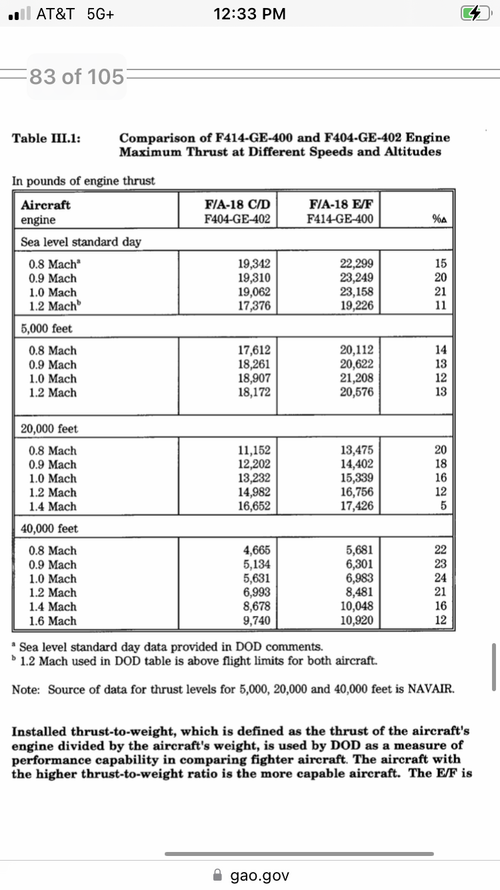
2x OG F414-400 provide as much power while weighing less than one F135.
 
Forget about VTOL. The A and C would've been been better off with a twin F414 derivative.

2x OG F414-400 provide as much power while weighing less than one F135.
Yeah that wasn't an option.
 
IMG_7893.png
If the F135 has significant dynamic thrust subsonic it might beat out the F414 by quite a bit
 

Similar threads

Please donate to support the forum.

Back
Top Bottom