GTX

All hail the God of Frustration!!!
Staff member
Senior Member
Joined
15 April 2006
Messages
7,753
Reaction score
10,959
Website
beyondthesprues.com
Hi Folks,

I am interested in information on the cancelled British CVA-01 carrier design. Any assistance would be appreciated.

Thankyou in advance.

Regards,

Greg
 
Re: CVA-01

Good discussion in DK Brown's Rebuilding the Royal Navy - Conway
 
Re: CVA-01

Here is a drawing I've done of CVA-01

CVA-013.jpg
 
Re: CVA-01

Hood said:
Here is a drawing I've done of CVA-01

CVA-013.jpg

Didn't the final CVA-01 design just have 2 cats? 1 waist and one bow?

Starviking

P.s. Nice pic - do you have a bigger version?
 
Re: CVA-01

CVA 01 name was Furious or Queen Elisabeth?
 
Re: CVA-01

My drawing is is one I did for an AH scenario which ditched the Sea Dart aft to save space and I added another catapult to match the US capability. Perhaps a better design than the real CVA-01, i never understood the reason for the Sea Dart when the escorts are armed with them. Overall though you get a good impression of her deck layout whcih I did not change.

Queen Elizabeth was the offical name and the second carrier (never offically ordered) would have been Prince of Wales.
 
Re: CVA-01

Hood said
Queen Elizabeth was the offical name
named after the monarch, as traditional for the first capital ship in a monarch's reign.
But the name I have seen for the second ship was Duke of Edinburgh the title of the Queen's husband. [name used before for an armoured cruiser about 1900]
CVA01 was cancelled in 1966 with no material work done, but the investiture of her eldest son Charles as The Prince of Wales took place on 1st July, 1969.
But none of the names for the second ship, if any, were official.
 
Re: CVA-01

Triton asked
HMS Queen Elizabeth? Should it not be HMS Queen Elizabeth II to be named for the current monarch?
Strictly and logically speaking, I suppose you are right. But:
1. traditionally the first ship of the line in a monarch's reign was Royal George, or Royal Edward etc, taking no account of the number of kings of that name. But King Edward VII broke with tradition, preferring ... HMS King Edward VII, a title he had chosen himself, in spite of being known for decades as Prince Albert before he became king.
The second HMS King George V was so named at the insistence of King George VI, (with his brother, the uncrowned and abdicated King Edward VIII commemorated by his former title (HMS Prince of Wales) and King George VI himself by his former title (HMS Duke of York)
2. HMS Queen Elizabeth is a (so far) unique name in the Royal Navy, but a very famous one, giving (good?) reason to revive it, and
3. they are Her Majesty's ships, and she approves the names, as did the monarchs before her.

Tradition is a funny thing, sometimes reviving things buried in the past (like this thread!)
 
Re: CVA-01

Hood said:
i never understood the reason for the Sea Dart when the escorts are armed with them.

Same logic that put Terrier on US carriers of the same era. Dispersed formations for nuclear warfighting (i.e., wide spacing to ensure that a tactical nuclear warhead would only destroy one ship) meant that there was some value in fitting long-range SAMs on high-value targets to engage missiles that leaked past the screen at the maximum possible range. The steadily increasing performance of long-range SAMs, and thus the ability of the escorts to extend their engagement envelopes over the HVU without getting the ships too close together made it less appropriate by the 1980s.

Dispersed formations also caused serious consideration of high-performance hull sonars on carriers in the same era, to deal with subs that slipped past the screen. In the post-war USN, only USS America was so equipped, but the British Invincibles have the same sonar as many of their ASW escorts.
 
Re: CVA-01

smurf said:
Triton asked
HMS Queen Elizabeth? Should it not be HMS Queen Elizabeth II to be named for the current monarch?
Strictly and logically speaking, I suppose you are right. But:
1. traditionally the first ship of the line in a monarch's reign was Royal George, or Royal Edward etc, taking no account of the number of kings of that name. But King Edward VII broke with tradition, preferring ... HMS King Edward VII, a title he had chosen himself, in spite of being known for decades as Prince Albert before he became king.
The second HMS King George V was so named at the insistence of King George VI, (with his brother, the uncrowned and abdicated King Edward VIII commemorated by his former title (HMS Prince of Wales) and King George VI himself by his former title (HMS Duke of York)
2. HMS Queen Elizabeth is a (so far) unique name in the Royal Navy, but a very famous one, giving (good?) reason to revive it, and
3. they are Her Majesty's ships, and she approves the names, as did the monarchs before her.

Tradition is a funny thing, sometimes reviving things buried in the past (like this thread!)

Thank you for the information. ;D I guess I am necroposting, but I was curious why the ship was named Queen Elizabeth without the numerals. I presume that in the United Kingdom there would be no question of whether the ship was name for the current monarch or Queen Elizabeth I.
 
Re: CVA-01

Triton said:
HMS Queen Elizabeth? Should it not be HMS Queen Elizabeth II to be named for the current monarch?

I seem to remember that they're more named after the previous ships to bear the names rather than the current monarch and Prince Charles, so they'll most likely keep the current names even if the Queen dies before they enter service.
 
Re: CVA-01

Yes, I agree with RA. I think the tradition is now "adapted"
 
Re: CVA-01

TomS said:
Hood said:
i never understood the reason for the Sea Dart when the escorts are armed with them.

Same logic that put Terrier on US carriers of the same era. Dispersed formations for nuclear warfighting (i.e., wide spacing to ensure that a tactical nuclear warhead would only destroy one ship) meant that there was some value in fitting long-range SAMs on high-value targets to engage missiles that leaked past the screen at the maximum possible range. The steadily increasing performance of long-range SAMs, and thus the ability of the escorts to extend their engagement envelopes over the HVU without getting the ships too close together made it less appropriate by the 1980s.

Dispersed formations also caused serious consideration of high-performance hull sonars on carriers in the same era, to deal with subs that slipped past the screen. In the post-war USN, only USS America was so equipped, but the British Invincibles have the same sonar as many of their ASW escorts.
Which is why until quite late in the design process CVA-01 also had an Ikara launcher.
 
Re: CVA-01

Two official artist's impressions as the CVA-01 design appeared in the summer of 1965.

Bottom is an unofficial outline drawing of the final (November 1965) design for CVA-01.
Notice the much shorter cats and reduced width Alaskan taxiway compared with the plan above. The bridle catchers at the end of the catapults are prominent.
http://frn.beedall.com/cva01.htm
 

Attachments

  • cva01-diag.jpg
    cva01-diag.jpg
    32.5 KB · Views: 677
  • cva01-1.jpg
    cva01-1.jpg
    51.6 KB · Views: 597
  • cva01-2.jpg
    cva01-2.jpg
    70 KB · Views: 630
Re: CVA-01

Is it just a case for my ophtalmologist, or is the "Alaskan Highway" on the artist's
impression really much wider, than on the line drawing ? ;)
 
Re: CVA-01

Jemiba asks
is the "Alaskan Highway" on the artist's
impression really much wider, than on the line drawing ?
I don't know about that, but the design continued over about 3 years, and though "the basic layout was unchanged" (D K Brown), there were various problems - radar fit especially - affecting the size of the island.
The plan views in DK Brown's Rebuilding the Royal Navy and in N Friedman's British Carrier Aviation are rather different, one with a narrower island, for example. It depends on the date and version (as well as on the artist's interpretation if it's an impression not a plan.)
But I think the three posted are intended to be the same (final?) version, though the artists' impressions are not identical - see the bows.
 
Re: CVA-01

I suspect the diagram is a bit dodgy based on the position and width of the wires.

Always the big issue for me, is the locaion of the wires on the final design, as the first wire seems to place the nexus of centerline (angled deck's that is) and the wire outside the 72ft radius of the locus of minimum ship motions....but then did'nt CVA-01 have a bulbous bow? In which case perhaps this pushed that locus back?

I do have a picy of the deck layout of CVA-01, from some book long ago. Maybe I should dig it out, but then not remembering the title, or having permission to use that image I shall refrain.
 
Re: CVA-01

Jemiba said:
Is it just a case for my ophtalmologist, or is the "Alaskan Highway" on the artist's
impression really much wider, than on the line drawing ? ;)

I wonder, how did it get the name "Alaskan Highway"?
 
Re: CVA-01

Just a guess: Because bringing aircraft along this way in bad weather, would have been
as pleasant, as moving them along a highway in Alaska during the winter ? ???
Clearance to the superstructure on one side and to the edge of the deck to the other
probably would have been quite small ...
 
Re: CVA-01

originally Alaskan Taxiway in
http://navy-matters.beedall.com/cva01.htm which has most of what anyone might want on CVA-01, including changed width (on diagram at least) of Alaskan Highway).
Alaskan Highway was built in WWII as an alternative 'backdoor' route to get supplies, especially aircraft I think, to Russia, instead of Arctic convoys round Norway.
http://www.pbs.org/wgbh/amex/alaska/filmmore/pt.html.
 
Re: CVA-01

rickshaw said:
Jemiba said:
Is it just a case for my ophtalmologist, or is the "Alaskan Highway" on the artist's
impression really much wider, than on the line drawing ? ;)

I wonder, how did it get the name "Alaskan Highway"?

I think it may have been because there's a highway from the lower US to Alaska which must, perforce, go outside the US (i.e. through Canada). Maybe the designers saw the fact that their path was going 'outside' the island was a similar situation.
 
Re: CVA-01

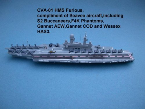
Photograph of restored Admiralty model of CVA-01 used for wind tunnel testing and is now on display at the Fleet Air Arm Museum, Yeovilton. The only other surviving contemporary model of CVA-01 has been loaned to Lockheed Martin's Ship Suitability Center, Fort Worth, Texas, and forms part of a display there.
http://navy-matters.beedall.com/cva01.htm

The wind tunnel model has been restored to show the unusual flight deck layout, which was intended to support concurrent aircraft launching and landing operations. The landing area is angled at just 3.5 degrees off the fore-and-aft axis (much less than on United States Navy carriers) and considerably off-set to port on a massive over-hang. The large island is placed inboard to allow a track way outboard for taxiing aircraft. The aft starboard deck edge elevator (lift in UK parlance) so as not to interrupt landing operations, while another inboard lift forward of the island and slightly to starboard of the center line is located so as to be useable in severe seas. (On smaller carriers, deck edge elevators are often swamped by waves.) The "Pri-Fly" (Flyco to the Royal Navy) is prominently located out over the flight deck for a good view.

However, the unusual flight deck design appears to result in significant loss of area, and may not have proved optimal in service.

Text from CVA-01 display at Lockheed Martin's Ship Suitability Center.
http://frn.beedall.com/images/cva01-display.jpg
 

Attachments

  • cva01-model.jpg
    cva01-model.jpg
    26.6 KB · Views: 545
Re: CVA-01

TsrJoe said:
the final design for CVA.01 did indeed have a 'bulb bow' as shown in drawings held at The National Archives, Kew, ill see if i can dig out my copies and post them up

Now that is a very interesting development, especially considering how many decades it has taken the USN to accept the obvious hydrodynamic advantages of the bulbous bow.

I do have to wonder if the RN was privy to the Japanese wartime research on the subject?
 
Re: CVA-01

They where discussing the merits of a bulbous bow during the 1952 CV effort. So its no surprise to see it on CVA-01.
 
Re: CVA-01

zen said:
They where discussing the merits of a bulbous bow during the 1952 CV effort. So its no surprise to see it on CVA-01.

Well, that would put the RN ahead of the western civilian research on the topic.

It does lead to the question of whether the British had full access to the Japanese wartime research, which apparently was quite exhaustive. Obviously, the USN didn't make very much use of the information, but I do have to wonder if it was passed along to the UK?

So, was the bulbous bow based on Japanese research, or independent British efforts? As I recollect, the bulbous bow had been tried as late as the 1930s on several western ocean liners, but the benefits we're clearcut until the 1980s, when computer modeling finally allowed an advance beyond the research that was performed by Japan 40 years earlier.
 
Re: CVA-01

I'm sure I remember reading that the US tried bulbous bows on one of their cruisers in the 1930's and that the RN did model trials around the same time.
The Dulin and Garzke US Battleships book mentions testing of bulbous bows and although they do not show lines plans the deck by deck plans do show the hull widening at the hold level for all the ships.
On page 106 there is a launch photo of Iowa which very clearly shows the bulbous bow form.
Also I have seen a photograph of one of the Italian cruisers of the 1930's with a small bulb of similar form to that in the Iowa so I'm sure most navies investigated them between the wars

The problem with bulbous bows is that they only reduce the hull resistance over a limited range of speeds and drafts. Outside that range they increase resistance.

Most merchant ships operate either in fully loaded condition and around 85-90% of full power, or in ballast and again at 85-90% of full power. The main exception being container ships.
For conditions of full load/sea speed it's easy to work out the optimum for of bulb, but this will only provide savings near to those condition.
In ballast the bulb will usually break the surface and then it will increase the resistance due to the bow wave though it will give a fractional increase in waterline length.
Usually the resistance due to wave making will outweigh the reduction due to increased length.
The other perceived advantage is that the increased buoyancy forward will reduce pitching and thus the loss of speed from this cause (and perhaps lessen the chance of damage from waves coming over the bows).
That is why many short and/or slow merchant ships have bulbs which confer no advantages at any condition of draft or speed.

Warships generally operate within a more limited range of drafts, but a much greater range of operating speeds.
I seem to remember that it was because of the limitations of the speed range that they were not adopted earlier by the RN.
The RN were looking at fairly small bulbs so I guess the advantage of reduced pitching was either not perceived or was not thought sufficient reason for adoption.

It would be interesting to know whether the bulb planned for CVA-01 was designed to be effective at maximum speed (to increase the maximum), at cruising speed (to increase the range), or was purely to reduce pitching and thus I guess help aircraft operation.
 
Re: CVA-01

Well the discussions in the 1952 CV effort where mentioning a bulbous bow and its possible effect on pushing the locus of minimum ship motions further sternwards. Its that locus that dictates the location the wires, and in consequence a host of characteristics that determine the carriers flight deck and hull.

In essence you should start your CV design from the pullout distance, spacing of the wires and then the locus of minimum ship motions. Then factor in how much beyond that you want for the flight deck and how much overhang at the bow. With all that you can then get the length of the ship and then its a debate on how much beam.

So if a bulbous bow pushes that locus back, if you can accept a shorter 'undershoot' or 'ramp' to the wires then you can produce a shorter CV.

Considering the limitations of the drydocks in question during that process, that would drive the idea of looking at a bulbous bow if it produces the desired result.


If you calculate this locus and draw a 72ft circle on CVA-01, based on the old assumption its 25% of waterline length from stern, then you'd find the first wire is completely outside that circle, which is the only deck plan I 've seen like that. So presumably the bulbous bow is producing that effect?
 
Re: CVA-01

That is why many short and/or slow merchant ships have bulbs which confer no advantages at any condition of draft or speed.

Beg to differ, the vessels are trimmed for optimum performance - owners are not known for wantonly wasting fuel.

On vessels where there is a wide draft range - typically bulk carriers, crude carriers, yes they run bulbous at load draft but the underside of the bulb is often formed as a wave piecer to allow the hull to act efficiently in that condition.

A lot of bulb research done in the UK for merchant vessels way before the more conservative naval offices took it up. Bulbs were often expressed as a percentage of the prismatic coefficient. Now they are generally optimised for the designed operation envelope of the vessel. Some vessels were found to perform significantly better when both bulbous and head down by some margin.

The RINA did countless studies over the years, I was involved with some and also data recording and voyage recording on a lot of vessel types.

(have 36 years deep sea experience ...)
 
Re: CVA-01

Here is an interesting table comparing some of the draft designs for what became CVA-01. The larger ships are because the original RN specification required the ability to deploy 64 strike recce aircraft and 32 fighters (via at least two ships) as the minimum force needed to sustain land and sea operations outside of land based air cover.
 

Attachments

  • New_Aircraft_Carrier.png
    New_Aircraft_Carrier.png
    107.4 KB · Views: 776
Re: CVA-01

But wait there is more... the table above is the 1960 designs, but 1962 the RN was looking at the following. Still considering the larger four shaft 40-48 strike fighter designs.
 

Attachments

  • New_CV_62.png
    New_CV_62.png
    84.5 KB · Views: 763
Re: CVA-01

Abraham

Fascinating tables. The Fighter/Attacker design in 1962 was supposed to take over from the Buccaneer in the 70s. Such big ships would have been able to operate the US F111B/TFX.

The double radar and massive missile loading ( 2 Seadart launchers and 1 Ikara) did not survive.

Makes me wonder if the US ever planned to fit ASROC on its sonar equipped carriers.

Random musings

UK 75
 
Re: CVA-01

Those tables are from Anthony Gorst's contribution to The Royal Navy 1930-1990: Innovation and Defense, a whole chapter dedicated to CVA01, edited by Richard Harding and published by Cass in 2005 and currently available on amazon. Gorst gives the best account of CVA01 I have seen to date including why the number of 3D radars and Sea Dart launchers both fell to one each and why Ikara was deleted. The book itself is well worth a purchase. If we are going to post scan's of authors research we should probably state the source so we at least give them credit.
 
Last edited:
Re: CVA-01

uk 75 said:
The Fighter/Attacker design in 1962 was supposed to take over from the Buccaneer in the 70s.

This is the OR.346 aircraft that the RN planned to acquire in both strike and fighter versions to replace the Buccaneer and Sea Vixen. Until sights were trimmed to P.1154 and Spey Phantom.

uk 75 said:
Such big ships would have been able to operate the US F111B/TFX.

Nope, even the bigger CVA-01 options were still limited to the same sized aircraft as the actual CVA-01 planned build. They could just carry more OR.346 aircraft. Though the innovation of the parallel flight deck meant a larger ship wasn’t so important to achieve 36 strike fighters.

uk 75 said:
Makes me wonder if the US ever planned to fit ASROC on its sonar equipped carriers.

The RN was planning in the 1960s of deploying their carriers in a very different way to the USN. The RN carrier group was to be widely dispersed with no close escort for the carrier. So CVA-01 had to be able to defend itself which was why Sea Dart and Ikara were planned. In the end Ikara was removed because it clashed with the hangar space, in particular the engine test area on the fantail.
 
Re: CVA-01

The story of the parallel flight deck and Alaskan Highway on the CVA-01 is fascinating.

The first significant change to the design occurred in December 1962 with the adoption of an innovative new flight deck design that aimed to increase the aircraft complement without adding to displacement. Up to this point all the detailed design studies had envisaged conventional angled decks, the landing area of the flight deck being offset at anything up to 8 degrees to port of the centre line of the ship; this innovation, invented by the Royal Navy in the early 1950s and fitted to existing carriers, took the flight path of landing aircraft away from any aircraft parked in the forward deck park. However the new design, produced following a Fleet Work Study, recommended reducing the angle of the flight deck to 2 ½ degrees by extending the width of the flight deck aft, thus moving the landing area 50 ft to port and forward. This radical change had the effect of increasing the total flight deck area by 2.8 per cent (some 3,500 square feet) but increased the parking area, clear of landing and launching aircraft, by 32 per cent (10,000 square feet), allowing an extra five aircraft to be parked clear of the landing area, increasing the total complement of OR346 aircraft by two to 32. The new design, by widening the flight deck, also allowed a more flexible movement of aircraft on what was likely to be a crowded flight deck by introducing a two-way traffic stream using an ‘Alaskan Highway’ outboard of the island and the extra deck space created inboard of the island. Moreover, the new design created space for an engine running-up area, regarded as desirable by the air departments from the beginning, from the hangar deck onto the now open quarterdeck.

TNA: PRO, ADM 1/26653, ‘Work Study Number 2 – Flight Deck Layout New Aircraft Carrier Design’, 1 Oct. 1962.

This quote and the above tables are from the CVA-01 chapter in the following:

“The Royal Navy 1930-1990: Innovation and Defense”, ed. R. Harding

Available as a Google Books review at

http://books.google.com.au/books/about/The_Royal_Navy_1930_1990.html?id=bw46M1qI9gMC
 

Similar threads

Please donate to support the forum.

Back
Top Bottom