flateric said:
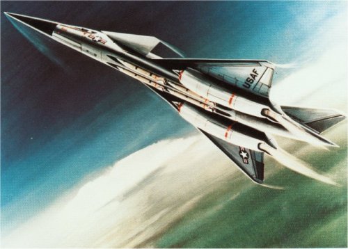
It really did look like your wind tunnel model...and now I think of another Eric Simonsen photo-collages...

Thank you very much for the articole.

I always wondered if it was a sort of photo-trick.
Anyway, by since, I never seen such type of aircraft in picture or in drawing....

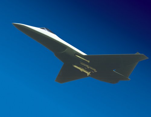
Respect the Boeing design the "Mystery Aircraft" is sleeker (not so much anyway), probably is two-seater (because it is possible to see a small window in the very back of the pilot's cockpit), it has a greater fin tail and it also huge winglets.

BTW the two aircrafts share almost the same shape, and general configuration as also the engine's canisters.
 
archipeppe said:
The Model 985-430 seems to have something in common with my avatar.....

didn't know it had a canard. The pic I posted doesn't have one but maybe it's retractable. (Boeing Pre-ATF thread. Maybe these should be moved?)

index.php
 
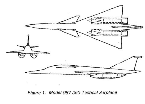
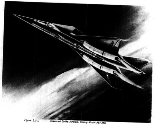
identified as Model 987-350
 

Attachments

  • ATF_Boe1.jpg
    ATF_Boe1.jpg
    72.9 KB · Views: 691
A twin engine delta-wing tactical airplane concept developed by Boeing in conjunction with the Air Force sponsored air-to-ground (ATS) studies.

This Mach 2.2 supercruiser airplane, Model 987-350, is characterized by its underwing propulsion units incorporating half-round axisymmetric inlets with vectoring two-dimensional
exhaust nozzles and canard trim system. The 987-350 wind tunnel model i s a 10.5% scale adaption of the twin engine ATS supercruiser airplane with a wing span of 37.8 inches and a body length of 100.5 inches. The variable wing twist and camber design utilized for the Mach 2.2 prototype airplane was incorporated into the model wing and canard design.

Source:
AIAA-83-1224 STOL Wind Tunnel Test Results for a Tactical Supercruiser
 

Attachments

  • 987-350.jpg
    987-350.jpg
    32.1 KB · Views: 891
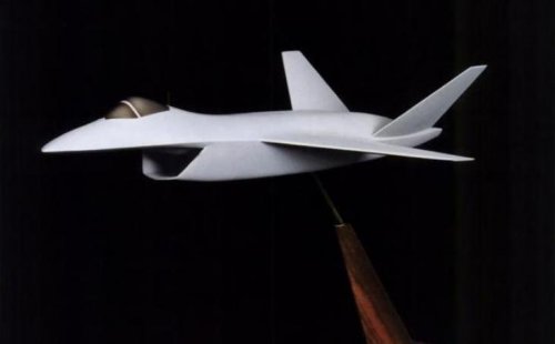
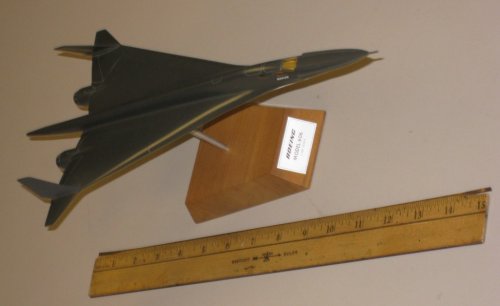
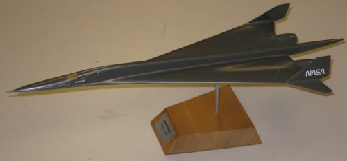
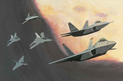
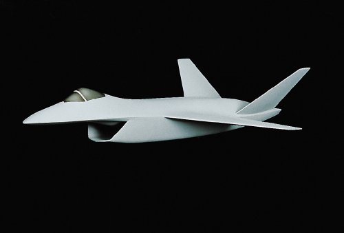
Model of Boeing Advanced Tactical Fighter (ATF) design submission.

According to F-22 Raptor (Enthusiast Color Series) by Bill Sweetman, MBI Publishing Company, 1998:
Boeing earned fourth place in the Dem/Val contest with this V-tail, diamond wing design. The single shark-mouthed inlet fed both engines--a unique and not necessarily desirable feature in a fighter, because of the risk that an engine failure or stall in one engine would affect the airflow into another. The inlet reappeared in Boeing's Joint Strike Fighter design. Like the F-22, it had a ventral bay for medium-range missiles and side bays for AIM-9s.

Additional photographs of this model can be found earlier in this topic:
http://www.secretprojects.co.uk/forum/index.php/topic,398.msg2543.html#msg2543
 

Attachments

  • BoeingATF.JPG
    BoeingATF.JPG
    14.7 KB · Views: 4,432
overscan said:
As is typical for Boeing, 985 family was a lot broader than this.

Here are some more members from:

http://www.dtic.mil/srch/doc?collection=t2&id=ADA259291

This link is dead. Do you have the report title so we can find it on DTIC?
 

Attachments

  • DF-SC-82-10593.JPEG
    DF-SC-82-10593.JPEG
    36.3 KB · Views: 985
I look at that and I find myself wondering if they got the wrong picture with the description. ???
 
I think it's a very cool looking design, but the structure for those curved wings had to be a heavy, compared to normal cantilevered wings.
 
Sundog said:
I think it's a very cool looking design, but the structure for those curved wings had to be a heavy, compared to normal cantilevered wings.

I'm not so sure. I am not an expert so am probably wrong. But some sort of geodesic style might work. with more than one wing spars diagonally going foward and more than one spars diagonally going backwards into those wing shapes with little weight panalty.... might work. But then i am not an engineer...so it still might not be possible.... because if it was it might have been done.
 
Kokoro said:
Sundog said:
I think it's a very cool looking design, but the structure for those curved wings had to be a heavy, compared to normal cantilevered wings.

I'm not so sure. I am not an expert so am probably wrong. But some sort of geodesic style might work. with more than one wing spars diagonally going foward and more than one spars diagonally going backwards into those wing shapes with little weight panalty.... might work. But then i am not an engineer...so it still might not be possible.... because if it was it might have been done.

Well, I am an engineer, and now that I think about it, I think they mill the main spars out of a single forging, but I don't recall at that moment. So, if so, they might not be that much heavier, but they are going to cost a hell of a lot more due to the size of the forging you would have to mill those from due to their curvature.
 
flateric said:
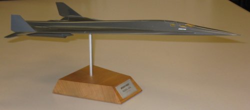
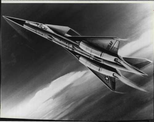
Boeing 1979 high speed heavy iterceptor, 45 000 kg class, and this-design-based SSBJ patent images

Since it has come up again, that's a Model 606. Probably a Model 733-606-12. Model 733 was a general holding-pen of a designation for Boeing SST designs, and there was a series of Model 733-606-XYZ designs (also at least one 733-602) that were not SSTs, but demonstrators, bombers and interceptors based on SST work. I don't really have much on them, though.
 

Attachments

  • 606a.jpg
    606a.jpg
    51.9 KB · Views: 1,574
  • 606b.jpg
    606b.jpg
    69.2 KB · Views: 827
  • 606c.jpg
    606c.jpg
    57.7 KB · Views: 623
Sundog said:
Well, I am an engineer, and now that I think about it, I think they mill the main spars out of a single forging, but I don't recall at that moment. So, if so, they might not be that much heavier, but they are going to cost a hell of a lot more due to the size of the forging you would have to mill those from due to their curvature.

Forgings are $$$$ especially if they're out of titanium. :eek:
 
Orionblamblam said:
Since it has come up again, that's a Model 606. Probably a Model 733-606-12. Model 733 was a general holding-pen of a designation for Boeing SST designs, and there was a series of Model 733-606-XYZ designs (also at least one 733-602) that were not SSTs, but demonstrators, bombers and interceptors based on SST work. I don't really have much on them, though.

I wish I had copies of the detailed drawings I saw for this concept. Of course, if I had, I would have caused trouble for my university as we were clearly told not to copy them. We had drawings, I believe for the supercruise demonstrator version of that design, and also some very detailed configuration drawings for the Boeing, Douglas, and Lockheed SST concepts from the mid '80s. Also, these were on 11" x 23.4" or 34" paper IIRC. I think they were kept in a binder and they folded out 3 or 4 pages, so the entire fuselage fit on a sheet and they had all kinds of detailed info on them.
 
Great find with the Boeing Model 985 Micro-Fighter study!! (and just as impressive was the Airborne Aircraft Carrier C-5 / B747!!)

You know as much as it may seem crazy- both the concept and the size of the Model 985 Micro-Fighter, I am sure that the argument was the same for the General Dynamics F-16, when the USAF first had its concept put before it - especially so when one considers the then trend of ever increasing size and weight of that generation fighter/fighter-bomber designs!

If I may
I wish to highlight some of the things that gained my attention and get the forums feed back.
Evaluation led to the definition of 1980 IOC and 1985 IOC concepts for Micro-fighter Airborne Aircraft Carrier Systems.
Do you think this OIC dates was attainable?

Launch stations located outside the ground radar coverage require fighter
interdiction radii of 100 to 300 n.mi.
Does this seem an adequate standoff/launch range?
And if it had of been put into service (both Micro-Fighter and Airborne Aircraft Carrier) - would the likes of the Soviet/Russian S-300 SAM have made it obsolete very quickly????

summarizes the primary characteristics of the C-5A and 747F
when modified to the AAC configuration. The C-5A lacks endurance for multiple
sorties from each fighter. Modification to the 747 requires more weight for
the desired arrangement for fighter handling. Both designs can be made to
carry 10 fighters with space for on-board rearming but the C-5A loses some of
it capability to carry outsize cargo.
I can not but help wonder how much difference the Boeing CX-HLS design submission (the one the Air Force wanted!!) would have made over the Lockheed C-5 design???

turnaround Including rearming (of Micro-Fighter), is estimated to require 10 minutes per airplane.
Impressive!

Personnel requirements are 44 per airplane (Airborne Aircraft Carrier): an AAC (Airborne Aircraft Carrier) crew of 12, MF (Micro-Fighter) squadron of 14 and 18 supporting specialists.
Very interesting figures!

Operation of ten fighters in combat situations from a high altitude base
requires pressurized crew compartments and hangar decks. The launch and
recovery bays become airlocks to transfer tile fighters between environmental extremes
A potential major operational and safety factor!
Almost 'Battlestar Galactica' sounding.

With this capability recovery operations for mission aborts could be
initiated as early as 7 minutes after initial launch. A wide range of mission
times are probable. Intercept missions range from 10 to 24 minutes. Lo-level
strike missions range from 17 to 88 minutes and combat air patrol could be up
to 2.4 hours. The carrier has payload capability for at least three sorties
per fighter. Resulting time on station could range to 8 hours for all combat
air patrol.

Advanced Short Range Missile –
Two internally carried, tube launched, dogfight missiles are
postulated for the 1980 Micro-fighter. A wingless configuration with
vectored rocket thrust for high maneuverability and a body diameter
similar to AIM-9 or Zuni is considered feasible. Missile exhaust gases
are ducted overboard (open tube launch). Look-before-launch capability is provided by projecting the missiles guidance section through the wing leading edge frangible ports.
Sound like an impressive missile system - way before its day.
Does anyone have any information on this air-to-air missile?
Was it an actual program?
Was it intended only for the Micro-Fighter?

Two 1765 lb. ‘Smart bombs’ have been chosen for the primary air-to-ground mission. A folding fin derivative of this modular weapon is shown carried tangent at the wing-body intersection. Additional weapon carriage hard points are provided under each wing just inboard of B.L.46.5 to accommodate a variety of weapons. Potential performance gains resulting from wing-body intersection stores carriage should be evaluated during external store development and/or selection for the advanced technology Micro-fighter.
Again was there such a program as this 'Modular Weapon System' which is spoken about so much in the study?
I must say I do like the concept!!

A 1980 IOC Multi-Purpose Strike System (MPSS) would beast employ 10x747 AAC + 1x 747 AWACS. This complement provides 100 fighters (approximately 4 squadrons) for deployment to Europe in 8 hrs. from alert - on station and ready for combat with fighter crews rested and briefed.
Sounds like a Boeing salesman delight!
Although I would not dought or question this capability if the chance arrived!

Do you think the MF/AAC concept could have worked??????

Looking forward to anythink else that comes to light regarding this Micro-Fighter / Airborne Aircraft Carrier concept and studies!!!!!!!!!


Regards
Pioneer
 
Pioneer said:
Advanced Short Range Missile –
Two internally carried, tube launched, dogfight missiles are
postulated for the 1980 Micro-fighter. A wingless configuration with
vectored rocket thrust for high maneuverability and a body diameter
similar to AIM-9 or Zuni is considered feasible. Missile exhaust gases
are ducted overboard (open tube launch). Look-before-launch capability is provided by projecting the missiles guidance section through the wing leading edge frangible ports.
Sound like an impressive missile system - way before its day.
Does anyone have any information on this air-to-air missile?
Was it an actual program?
Was it intended only for the Micro-Fighter?

"Was it an actual program?"
There was a contemporary US program along those lines.
http://en.wikipedia.org/wiki/AIM-95_Agile
http://www.designation-systems.net/dusrm/m-95.html

There were others as well.
The UK's Taildog was very similar and quite ahead of its time. I understand that it ultimately formed the basis of the current ASRAAM program, 30 years after its initial successful test firings.
http://www.secretprojects.co.uk/forum/index.php/topic,178.0.html
 
Thanks for the heads up Brickmuppet!!

Regards
Pioneer
 
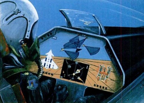
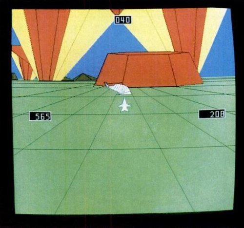
Boeing also studied cockpit concepts for the Advanced Tactical Fighter (ATF) program.

The Virtual Situation Display developed by Boeing shows major topographical features ahead of an aircraft. Red and yellow beams show the severity of threats from ground-based missiles and guns. The "ribbon" road in the sky shows the pilot path to minimize risk. The scene is viewed from a God's eye perspective; the pilot sees his own airplane from above and behind.

Artist's concept shows a possible ATF cockpit configuration with graphic displays showing enemy-fighter radar, weapon stores, engine status, navigational data, and best flight path.

Source: Brown, Stuart F. "21st-Century Superfighters" Popular Science October 1986 p.84.
 

Attachments

  • BoeingCockpitConcept.JPG
    BoeingCockpitConcept.JPG
    54.5 KB · Views: 1,341
  • VirtualSituationalDisplay.JPG
    VirtualSituationalDisplay.JPG
    38.5 KB · Views: 1,331
ahh , being Fifteen again and impressed with all that incredible new tech so outlandish .
 
Boeing 1988 ad, calling for LO wizards. Hey, this RCS model is not not so far from real stuff!
 

Attachments

  • 1988-02-08-boeingatfhiring.jpg
    1988-02-08-boeingatfhiring.jpg
    97.5 KB · Views: 1,363
From Code One:
 

Attachments

  • ATF_Evol_part1_04_1267828237_8803.jpg
    ATF_Evol_part1_04_1267828237_8803.jpg
    79.8 KB · Views: 1,425
  • ATF_Evol_part1_02_1267828237_8698.jpg
    ATF_Evol_part1_02_1267828237_8698.jpg
    272 KB · Views: 1,439
  • ATF_Evol_part1_19_1267828237_3769.JPG
    ATF_Evol_part1_19_1267828237_3769.JPG
    197.9 KB · Views: 553
Triton said:
The scene is viewed from a God's eye perspective; the pilot sees his own airplane from above and behind.

...More commonly known as "Third-Person Shooter Mode".
 
Considering all of the advances in terms of avionics and processing power since then, and systems like EODAS, that still sounds like an interesting concept today.
 
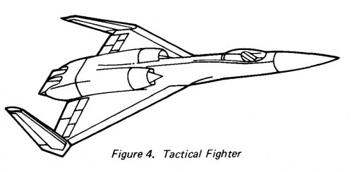
Boeing designers focused on the weapon bay and essentially designed the airplane around it. Wind tunnel results, especially those related to flight at high angles of attack, affected the arrangement, size, cant angles, and placement of the tails. The design used a single chin inlet with an internal splitter to feed the two engines. The inlet had an internal variable ramp (combined with the splitter) to reach its higher design speeds.

index.php


Source: http://www.codeonemagazine.com/article.html?item_id=40
 
...
 

Attachments

  • Boeing_1980_TF.jpg
    Boeing_1980_TF.jpg
    104.4 KB · Views: 436
  • Boeing_1980_SCV_1.jpg
    Boeing_1980_SCV_1.jpg
    157.2 KB · Views: 335
  • Boeing_1980_SCV.jpg
    Boeing_1980_SCV.jpg
    92.8 KB · Views: 410
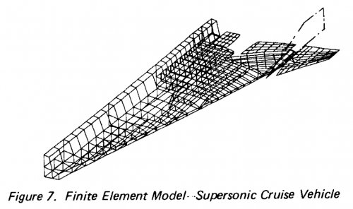
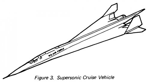
AIAA 1980-813
STRUCTURAL DESIGN LOADS FOR FUTURE AIRPLANES
P. Milns
Boeing Military Airplane Company, Seattle, Wash.
 
flateric said:
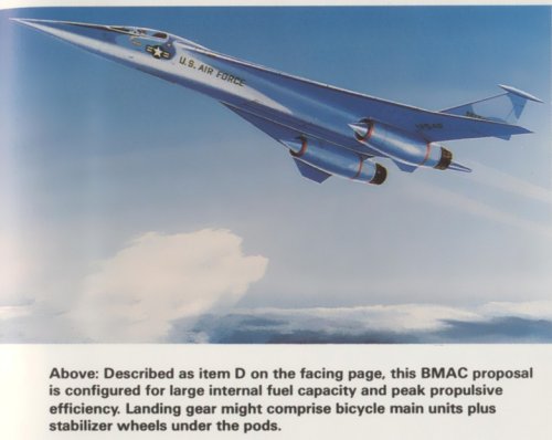
The same NASA study Boeing's submission for Middle East scenario (1 500 mile combat radius)
In colour, from 'Warplanes of the future' by Bill Gunston, page 45.
 

Attachments

  • Boeing_AFT_Item_D.jpg
    Boeing_AFT_Item_D.jpg
    96.4 KB · Views: 1,087
flateric said:
Originally posted by Sundog in McDonnell Douglas pre-ATF / ATF studies thread re-identified as Boeing's various airframe inlet concepts from

AIAA 80-1106
Performance Variations in High Aspect Ratio Subsonic Diffusers Due to Geometric Constraints in Supersonic Tactical Aircraft Inlet Installations
Jan Syberg and Joseph Koncsek,
Boeing Military Airplane Co.,
Seattle, Washington
Lewis Surber
Air Force Wright Aeronautical Laboratories
Wright-Patterson AFB, Ohio


And from DTIC;


http://www.dtic.mil/dtic/tr/fulltext/u2/a108300.pdf
 

Attachments

  • fighters.JPG
    fighters.JPG
    32 KB · Views: 2,229
http://www.ebay.com/itm/1981-Boeing-SST-Fighter-Press-Photo-/190704399749?pt=Art_Photo_Images&hash=item2c66de3585#ht_3164wt_1397


1981 [/size]Supersonic fighter This is the way The Boeing Co. believes it might be able to apply some of the technology it learned in developing a commercial supersonic aircraft to military supersonic cruise airplanes. close-coupled canard/delta wings and engines blended under the wing. The concept grew out of a NASA study competition. The plane Is designed to fly at Mach 2 with a combat radius of 500 miles. [/size]. Photo is 10.5” x 8.5” in size.
 

Attachments

  • $(KGrHqF,!qkE+nScZhpnBQBbr35Jdw~~60_57.JPG
    $(KGrHqF,!qkE+nScZhpnBQBbr35Jdw~~60_57.JPG
    86.3 KB · Views: 634
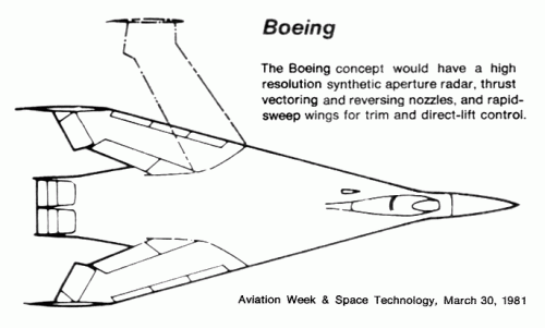
PaulMM said:
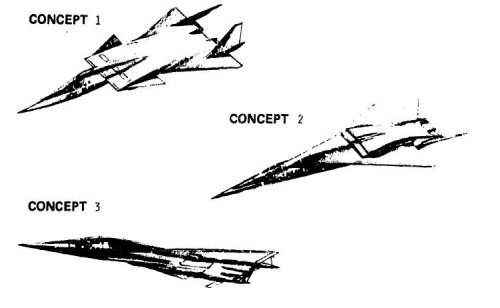
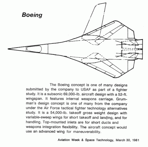
Boeing swing-wing concepts:

These appeared in a 1981 article from AW&ST.
I have extracted the text from the article and affixed it to each picture.
 

Attachments

  • Boeing fighter study 1.gif
    Boeing fighter study 1.gif
    39.1 KB · Views: 1,924
  • Boeing fighter study 2.gif
    Boeing fighter study 2.gif
    70.2 KB · Views: 3,945
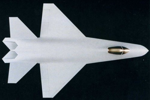
hmm...just wondering why kinda Boeing ATF finalist shown at great chart that Stephane has posted here - Model 864B - looks rather different from model we all know...
 

Attachments

  • Boeing ATF Model.jpg
    Boeing ATF Model.jpg
    145.3 KB · Views: 1,206
  • Boeing ATF Model 864B.jpg
    Boeing ATF Model 864B.jpg
    36.2 KB · Views: 1,149
PaulMM (Overscan) said:
A twin engine delta-wing tactical airplane concept developed by Boeing in conjunction with the Air Force sponsored air-to-ground (ATS) studies.

This Mach 2.2 supercruiser airplane, Model 987-350, is characterized by its underwing propulsion units incorporating half-round axisymmetric inlets with vectoring two-dimensional
exhaust nozzles and canard trim system. The 987-350 wind tunnel model i s a 10.5% scale adaption of the twin engine ATS supercruiser airplane with a wing span of 37.8 inches and a body length of 100.5 inches. The variable wing twist and camber design utilized for the Mach 2.2 prototype airplane was incorporated into the model wing and canard design.

Source:
AIAA-83-1224 STOL Wind Tunnel Test Results for a Tactical Supercruiser


My dear Paul,


here is also from NASA report,the Boeing Model 987-350;


http://ntrs.nasa.gov/archive/nasa/casi.ntrs.nasa.gov/19800075253_1980075253.pdf
 

Attachments

  • 987-350 1.JPG
    987-350 1.JPG
    40.5 KB · Views: 248
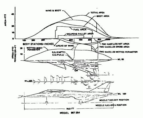
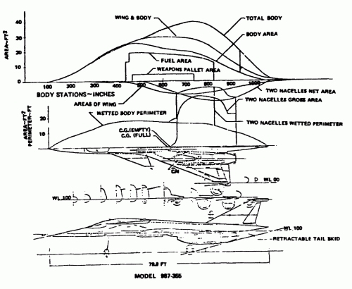
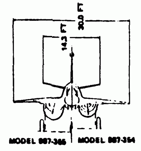
We've seen loads of stuff on the Model 987-350, but this particular variant, the Model 987-354, hasn't been mentioned here before. There is also a second variant mentioned, but the scan is so lousy it's impossible to determine the exact dash number. Looks like -366, but could also be -356 I guess...

The LUCID point of departure retained the basic planform and size of the Model 987-350 but incorporated Allison PD414-6 engines with axisymmetric flap nozzles. The resulting configuration is defined as the 987-354 and is shown in Figure 31. Also shown in this figure is a maximum thrust to weight (1.20)-sized version of the airplane. This version was examined to check for any configuration-oriented difficulties in incorporating the large engine size. From this study, no unworkable problems appear associated with the large engine size.

Source:
Life Utilization Criteria Identification in Design (LUCID)
Detroit Diesel Allison, June 1982
Air Force Wright Aeronautical Laboratories AFWAL-TR-82-2039
 

Attachments

  • 987-354.gif
    987-354.gif
    326.5 KB · Views: 364
  • 987-366 (maybe).gif
    987-366 (maybe).gif
    55.6 KB · Views: 385
  • 987-354 comparison.gif
    987-354 comparison.gif
    7.5 KB · Views: 335

Similar threads

Please donate to support the forum.

Back
Top Bottom