blackkite
Don't laugh, don't cry, don't even curse, but.....
- Joined
- 31 May 2007
- Messages
- 8,805
- Reaction score
- 7,668
Also enjoy the recent first page.


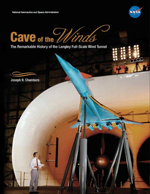
 www.nasa.gov