Hi folks
Regarding drive shaft :
1 : needs to properly handle the torque of the engine with long fatigue life. Torque is easily derived from max hp, and for a 4 stroke 4 s cylinder you need to multiply that value by 3. This is the load design .
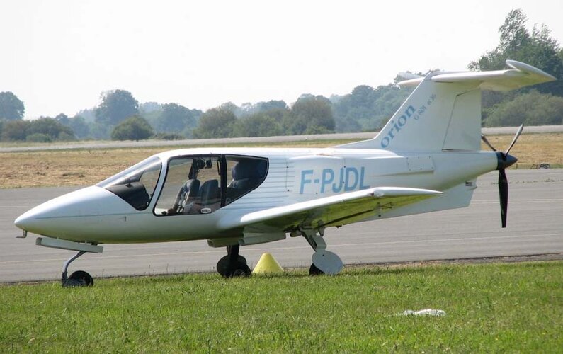
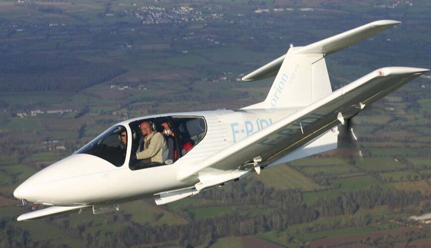
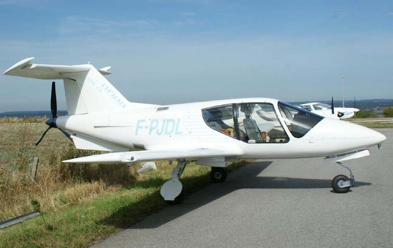
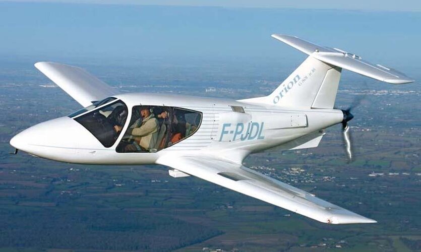
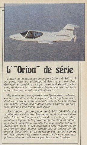
2 : at max rpm lateral divergence needs to be calculated . Typically not an issue for cf shafts but watchout for steel ones. The Orion shaft is 1966mm long. Diameter 89 wall thickness 1,6mm. Going longer than this is impossible as the lateral limit is about 3000 for steel
3 : torsional resonance needs to be computed. This can easily be done with a holzer model. It is a multidimensional spring mass in rotation. Inertia and torsional stiffness. We tune orion shafts to have torsion first mode at 50hz. 3000 rpm and we cannot go there with lycomings. This means forbiden band at 1500 +-75 as well as 750 and 375 .
4 : kickback at engine start are strictly forbidden. This is what overshresses the shafts
Regarding dampeners : no this is not what is needed. You need to know your resonance frequencies and never fly there. A dampener is a super soft spring that will dramatically lower your resonance frequencies.
You need to measure your engine crankshaft inertia and then measure all inertias with bifilar suspension like the rotax prop measurement method . You need to measure or calculate torsional stiffness of your shafts and critical « soft « parts.
Then apply holzer on that.
Look for an old thread on van’s forum regarding strange Subaru engine wear at 300h. DanH and rve6guy did exchange about all that and you will see how they tuned their reduction unit !
Cheers from the French orion guys.