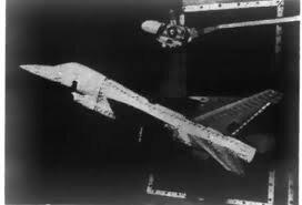
Anyone know any more about this Italian fighter? All I know is that it's from 1974, uses an RB199 engine with 7620kg of thrust, was part of the research for the eurofighter typhoon and was conceived as a replacement for the Fiat g91, following all roles that undertook. I have attached pictures and a source https://it.wikipedia.org/wiki/Aeritalia_AIT-320
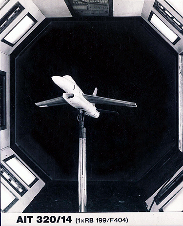
3. TESTS AT HIGH ANGLES OF ATTACK ON AN ADVANCED FIGHTER CONFIGURATION (AIT 320)
Within researches at AIT for the evaluation of typical new combat aircraft configurations, a model has
been finalised and wind-tunnel-tested for basic research and development up to high <* and f> values.
Several basic variants have been tested, like manoeuvre and high lift devices at wing leading (droop nose)
and trailing edge (flap), wing root strakes, vertical position and anhedral angle of the horizontal tail,
longitudinal position of the vertical tail, etc. Some selected results of test analysis are presented in
figs. 6 * 18. The following remarks can be done about the given results
a) Longitudinal characteristics
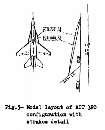
The most innovative among the variants tested are two kinds of wing root uncambered, sharp leading-edge
strakes differing in planformi strake 3 has triangular shape (straight leading—edge contour) whilst
strake 5 is ogee-shaped with cusped leading-edge contour. The relevant geometry characteristics are
sketched in fig. 5. The large lift gain obtained at high angle of attack through the stabilising effect
of the vortex flow developed by the strakes on the wing flow is evidenced by the comparison of the
tail-off lift curves shown in fig. 6. The lift improvements appear to be much higher in the clean
( g m 0°) configuration than at high lift ( £ f i - 40*) due to the detrimental effect of the vortex
flow from the strakes on the potential lift increment developed by the flaps. The implications on the
pitching moments (figs. 7 & 8) appear from the comparison of the strake-off and strake-on characteristics
to cause large reduction of stability and sudden kinks at both flap settings for the basic configuration.
The figures show that the stability problems associated with strakes in the high- ot. range
can be cured by leading edge drooping ( & ^ - 30°) and by lowering the horizontal tail with respect to
the wing. The forward shift of tail-off center-of-pressure position with strakes due to the steadily in
creasing importance of the forward-located vortex lift with the angle of incidence is evident from
fig. 9.
b) Zero sideslip lateral -directional data
Presence of non-zero rolling and yawing moments in the wing stall incidence region is evident (fig. 10),
the rolling moment being affected mainly by the wing, whilst the yawing moment is influenced also by
the front fuselage (whose vortex system at high incidence may be asymmetric). A certain improvement in
the zero sideslip characteristics at the stall may be obtained by the strakes which stabilize the wing
flow.
c) Directional stability
The basic model configuration exhibits an acceptable level of directional stability up to and immediately
beyond the wing stall region, (.fig. 11). At an incidence of 15° a progressive decrease in stability
appears and at approximately 40° the configuration becomes directionally unstable; at higher angles of
attack there is a region in which the stability is restored. Prom the breakdown of the directional
stability, it is evident that the loss of stability in the post— stall range is due to the decrease of
the vertical tail contribution associated with the low energy wake shedding from the wing and fuselage
at high angles of attack (this phenomenon is evidenced also by the rudder effectiveness at zero sideslip,
as shown in fig. 11). A clear picture of the progressive immersion of the vertical tail in the wing/fuselage
wake when angle of attack is increased is given by the turn visualizations ehoum in figs. 12 - 13«
As the restoration of stability is exhibited by the fin-off contribution too, it is supposed that the
component responsible for this unexpected characteristics is the fuselage forebody. A similar phenomenon
but at lower incidence was discovered by NASA aerodynamicists during wind tunnel tests on an P-5 model
(ref. 5).
Wing strakes influence on the directional stability (figs. 14-15) may be summarized as follows;
- Clean configuration
At angles approaching the stall incidence, the strokes improve appreciably the directional stability,
for their vortex system delays the flow breakdown in the outer wing.
Beyond the wing stall, there is a sudden loss of stability for the straked configuration and the stabi^
lity level is markedly influenced by the strake planform: their effect may be correlated with the burst
of the vortex system on the strake. The strake 5 (gothic) shows a greater influence than strake 3 (tri
angular):for this strake, the loss of stability occurs at a higher incidence but the decrease is steep_
er so that the configuration becomes unstable at a lower angle of attack. This phenonenon is supposed
to be caused by a more violent bursting of the strake vortex (e.g. see the analogous effect on the Ion
gitudinal characteristics, i.e. the centre of pressure movement reported in fig. 9). A comparison of
the flow visualization between basic and basic +• strake 3 configurations (fig.16) substantiates the above
interpretation. Ftocusing attention on rudder tufts, it may be seen that for the straked configura
tion the flow is more regular than for the basic one at the same angle of attack.
- High lift configuration
With flaps down, strakes have less effect on directional stability (fig.15) for the same reason explai.
ned when dealing with longitudinal characteristics.
The effect of longitudinal position of the vertical tail is shown in the same figure where, apart from
the obviously reduced basic level, the sudden drop of stability is eliminated due to the reduced inter
ference of the fin with the wing and tail wakes.
To be noted that the results presented (especially the body contribution to the directional stability)
are strongly influenced by the test conditions (Reynolds number referred to the mean aerodynamic chord
Re m 870.000, and transition fixed on body nose and 5$ c of wing and tailplanes).
View attachment 758858
French magazine AMI had an article on the AMX predecessor AIT.311 AIT.315 designs in issue between 909 -914 it seems. Might be worth checking out.
Cheers Hesham. @Caecilius this issue is linked by hesham above.
In the mid-seventies, Aeritalia and Aermacchi separately developed various projects to take over from the G-91 and G-91Y tactical support aircraft, but also from the two-seater G-91T advanced trainer and operational conversion aircraft. Thus, the Gruppo Velivoli da Combatimento of Aeritalia designed, under the direction of engineer Giulio Ciampolini, a series of preliminary projects, including the G-291, directly derived from the G-91Y, AIT.311, with a moderately swept high wing, and AIT.315, characterized in particular by its single-track landing gear, with balance lifts located at two-thirds of the wingspan and its two guns mounted on top of the fuselage, behind the cockpit.
Close ties had already been established between Aermacchi and Embraer, mainly around the MB.326 licensed production program. It was in collaboration with the Brazilian firm that the design office headed by engineer Ermanno Bazzocchi worked on a project that met the needs of the Força Aérea Brasilera (FAB), the MB.340.The wind tunnel models of this machine show a silhouette close to that of the "Veltro" 2, with a high wing carrying six pylons for external loads and, at the ends, rails for launching "Sidewinder" missiles. We also note this air-to-air armament on AIT.315. On both sides, therefore, we were thinking of a secondary interception capability, or at least self-defense.
This site uses cookies to help personalise content, tailor your experience and to keep you logged in if you register.
By continuing to use this site, you are consenting to our use of cookies.

.jpg")