overscan (PaulMM)

Administrator
Staff member
Joined
27 December 2005
Messages
16,924
Reaction score
21,796
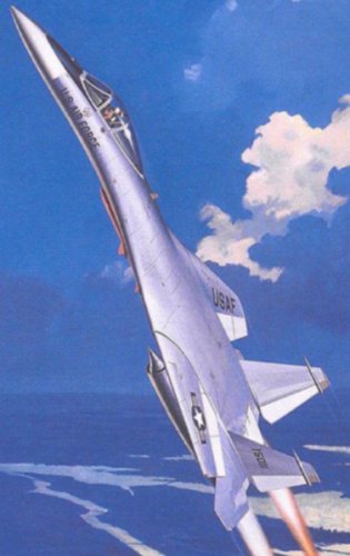
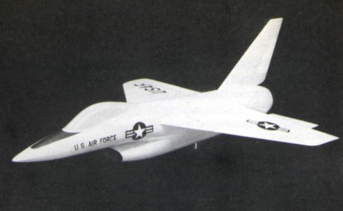
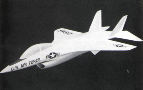
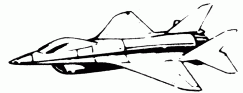
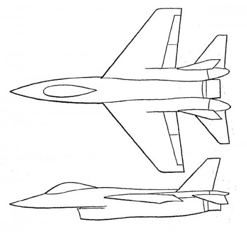
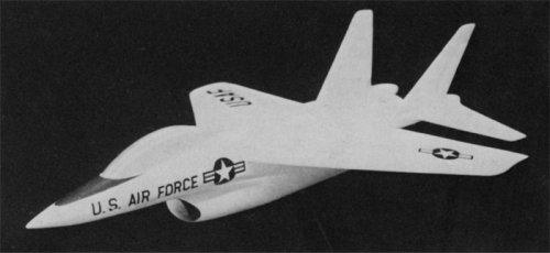
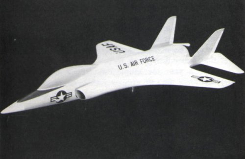
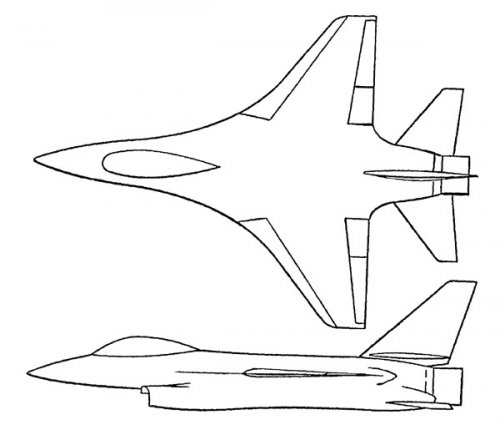
The F-16 has its origins in General Dynamics studies for the FX program.

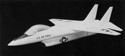
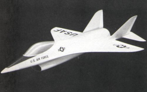
An RFP was issued in December 1965 for a Tactical Support Aircraft, specifying dual air-to-air and air-to-ground roles. The Air Force was thinking of a 60,000lb VG aircraft at this time. Grumman submitted a variable geometry design proposal in March 1966. From 1966, they began wind tunnel testing of their basic concept, which already featured a blended strake forward fuselage design; at this stage however, while sharp strakes were briefly examined, a blunt leading edge was preferred to prevent forebody separation.

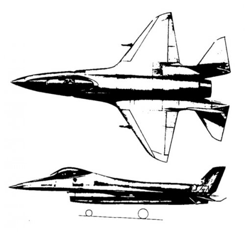
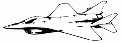
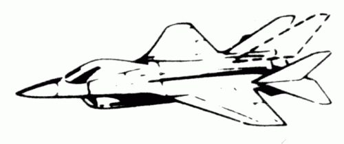
It was rejected and did not receive funding (Boeing, Rockwell and Lockheed were successful at this stage). General Dynamics carried on work on FX with company funds, along with lighter weight studies for the concurrent ADF (25,000lb) program. None of the chosen contractors produced anything impressive.

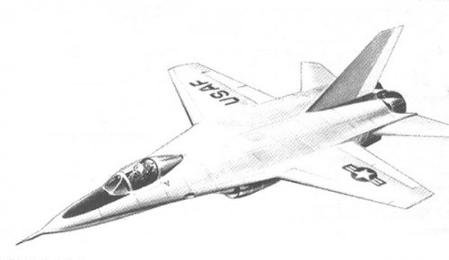
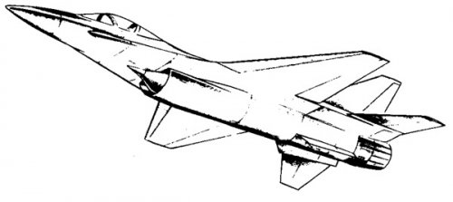
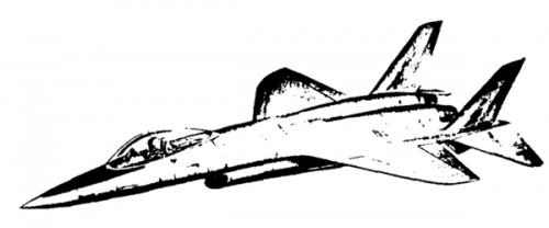
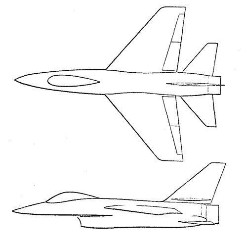
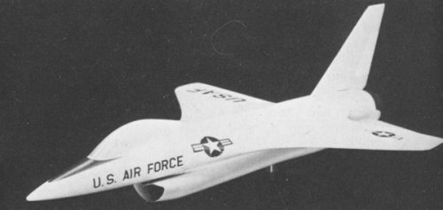
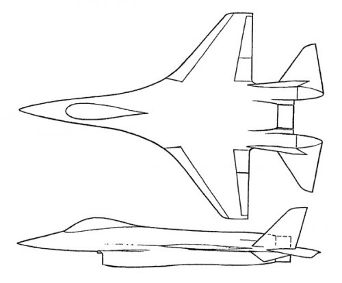
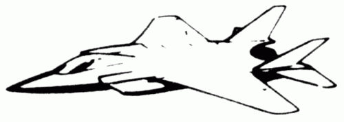
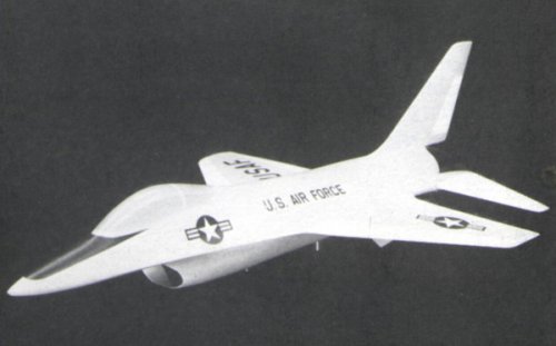
Thanks to the efforts of John Boyd and others on one hand and the unveiling of "Foxbat" on the other, in August 1967 a new FX (Fighter, Experimental) RFP was issued for a 40,000lb agile air superiority fighter. General Dynamics studied both variable geometry, which used wing/body blending and underwing intakes, and fixed wing designs.

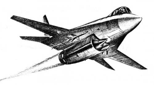
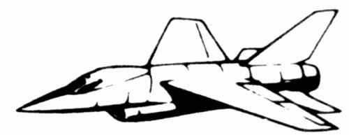
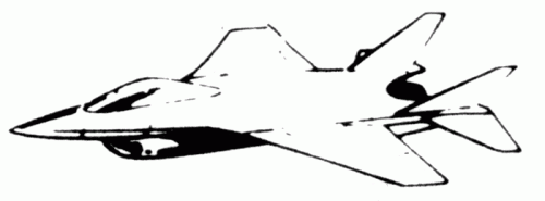
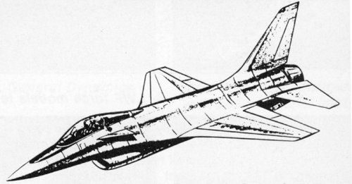
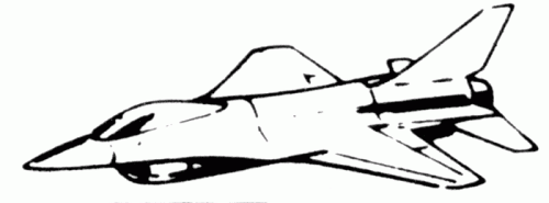
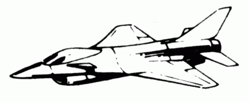
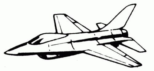
Through 1968 General Dynamics worked on a compliant FX bid; simultaneously, they worked in-house, using company resources, on a single engine lightweight fighter design.
 

Attachments

  • VG-FX.jpg
    VG-FX.jpg
    63.8 KB · Views: 4,778
  • Lightweight Fighter (single engine) .jpg
    Lightweight Fighter (single engine) .jpg
    40.2 KB · Views: 3,439
  • Lightweight Fighter (twin engine).jpg
    Lightweight Fighter (twin engine).jpg
    29.9 KB · Views: 5,675
  • FX (1968).jpg
    FX (1968).jpg
    30 KB · Views: 3,105
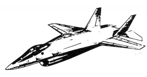
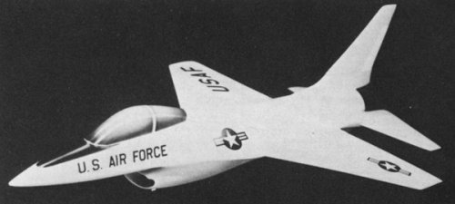
In August 1968 General Dynamics' bid for the FX program was rejected. They carried on working on the concepts explored by the lightweight single engine configuration, under the designation 404.

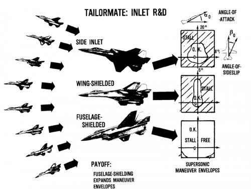
In 1969, they worked with NASA on Project Tailormate, a comprehensive study of stall resistance of various intake types and locations which gave General Dynamics great confidence in the underfuselage air intake. Other studies on
blended wing/body design, automatic flaps and slats, and other technical areas all fed into improving the design.

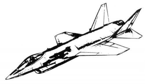
Twin and single engine designs were studied. Results showed that the single engine design was 20% lighter at the start of combat, had superior sustained turn rate and more rapid acceleration, while extensive reviews of accident rates showed no significant differences between one and two engines.
 

Attachments

  • Twin-Engine.jpg
    Twin-Engine.jpg
    26.2 KB · Views: 845
  • Single-Engine.jpg
    Single-Engine.jpg
    23.3 KB · Views: 912
  • Tailormate.jpg
    Tailormate.jpg
    96.4 KB · Views: 1,017
  • 404 (Other Variant).jpg
    404 (Other Variant).jpg
    44.6 KB · Views: 819
  • 404 Drawing.jpg
    404 Drawing.jpg
    42.9 KB · Views: 4,581
  • 404 Model.jpg
    404 Model.jpg
    48.4 KB · Views: 2,795
Serious development of the lightweight fighter started in late 1970. Initially in house, General Dynamics worked on the concept of a single engine, single seat fighter, armed with two wingtip Sidewinders and an internal gun.

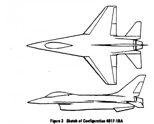
Two basic designs were studied, 785 and 401F. 785 was a very simple and comparatively low risk design with a conventional separate wing and body and single vertical tail. 401F was a blended wing/body design with twin vertical fins. Both designs used an underfuselage inlet location.
 

Attachments

  • 401 Model.jpg
    401 Model.jpg
    46.6 KB · Views: 691
  • 401F Plan.jpg
    401F Plan.jpg
    49 KB · Views: 714
  • 785 Drawing.gif
    785 Drawing.gif
    19.8 KB · Views: 529
  • 785 Model.jpg
    785 Model.jpg
    50.4 KB · Views: 568
  • 785 Plan.jpg
    785 Plan.jpg
    30.2 KB · Views: 1,766
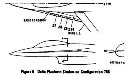
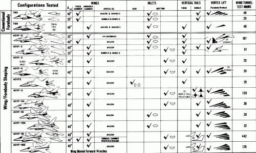
The inital twin tailed 401F design showed severe problems with directional stability at moderate to high AOA. It turned out that forebody flow separations and their resulting vortices were interacting with the vertical tails. Where the blunt forebody design had attempted to delay vortex formation, NASA Langley aerodynamicists suggested instead to try sharpening the strake leading edge to increase vortex strength, to dominate and stabilise the flow at high AOA. Over a three month period delta strakes were tested on 785 and its twin tailed 786 variant, while small canards, ogive and gothic strakes (and combinations thereof) were all tested out on the F401F series.The stability problems were basically resolved by the end of this period, though the detail strake design continued to be refined.

The 401F configuration went through many iterations. F-0, F-1, F-2, F-3, and F-4 were all basically twin tailed and tested different strakes, wing shapes and minor refinements.
 

Attachments

  • 401F-2 (Single Tail smiley inlet).jpg
    401F-2 (Single Tail smiley inlet).jpg
    30.4 KB · Views: 522
  • 401F-4 Drawing.gif
    401F-4 Drawing.gif
    15.4 KB · Views: 474
  • 401F-4 Model.jpg
    401F-4 Model.jpg
    46.4 KB · Views: 503
  • 401F-3 Drawing.gif
    401F-3 Drawing.gif
    17.1 KB · Views: 488
  • 401F-2 Plan.jpg
    401F-2 Plan.jpg
    35.2 KB · Views: 584
  • 401F-2 Drawing.gif
    401F-2 Drawing.gif
    19.9 KB · Views: 468
  • 401F-0 Drawing.gif
    401F-0 Drawing.gif
    19.8 KB · Views: 463
786 was a twin tailed version of 785.

401FS used sidemounted inlets; early models were initially D shaped, later revisions using horizontal wedge inlets were actually tunnel tested. This design series (401FS-0,1,2,3) was used more as a control benchmark rather than a serious configuration, as Project Tailormate had established the dominance of the underfuselage inlet location.
 

Attachments

  • 786 Plan.jpg
    786 Plan.jpg
    34.7 KB · Views: 473
  • 786 Model.jpg
    786 Model.jpg
    46.9 KB · Views: 488
  • 401FS Model (early).jpg
    401FS Model (early).jpg
    44.7 KB · Views: 1,834
  • 401FS Drawing (later).gif
    401FS Drawing (later).gif
    15.4 KB · Views: 475
The breakthrough design must be considered 404F-5. This design mated the forebody of the F401F-2 with the afterbody of the single tailed 785 design. F401F-5A added afterbody shelves and is looking quite F-16 already.
 

Attachments

  • 401F-5A Drawing (canard).jpg
    401F-5A Drawing (canard).jpg
    67 KB · Views: 539
  • 401F-5A Model.jpg
    401F-5A Model.jpg
    32.9 KB · Views: 456
  • 401F-5A Drawing.gif
    401F-5A Drawing.gif
    18.6 KB · Views: 418
  • 401F-5 Plan.jpg
    401F-5 Plan.jpg
    36.7 KB · Views: 444
  • 401F-5 Drawing.gif
    401F-5 Drawing.gif
    19 KB · Views: 391
In your first post, the third image down,

lightweight-fighter-twin-engine-jpg.11334


put a VG wing on it and it looks like the pic of the model OrionBlamBlam had on his website for a long time looking for identification.
 
Last edited by a moderator:
The next major step forward towards the YF-16 was 401F-10.


401F-10A added afterbody shelves which mounted the horizontal tail surfaces, as also seen on 401F-5A.

401F-16 marks the point where the basic F-16 configuration was achieved.
 

Attachments

  • 401F-10 Drawing.gif
    401F-10 Drawing.gif
    23 KB · Views: 356
  • 401F-10A Drawing.gif
    401F-10A Drawing.gif
    22.6 KB · Views: 343
  • 401F-10A Model.jpg
    401F-10A Model.jpg
    42.1 KB · Views: 413
  • 401F-10A Plan.jpg
    401F-10A Plan.jpg
    45.1 KB · Views: 527
  • 401F-16 Drawing.gif
    401F-16 Drawing.gif
    23.8 KB · Views: 403
  • 401F-16E Drawing.gif
    401F-16E Drawing.gif
    15.6 KB · Views: 449
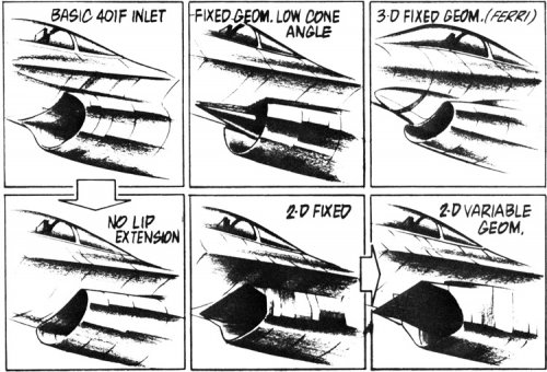
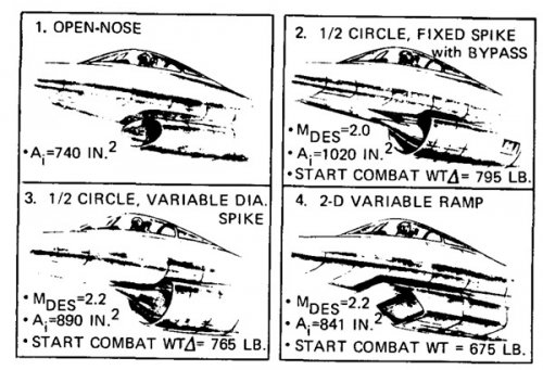
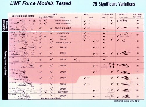
To show the vast number of different versions studied, here are some of the different inlet designs considered at different points, and then a table that shows all the different types of strake, wing, tail and inlet combinations wind tunnel tested.
 

Attachments

  • F-16 Variations.gif
    F-16 Variations.gif
    103.3 KB · Views: 1,038
  • GD-inlet-variants.jpg
    GD-inlet-variants.jpg
    143.4 KB · Views: 1,006
  • GD-inlet-variants2.jpg
    GD-inlet-variants2.jpg
    83.7 KB · Views: 896
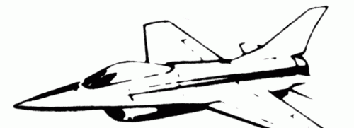
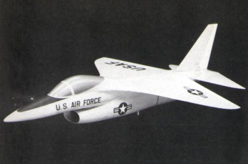
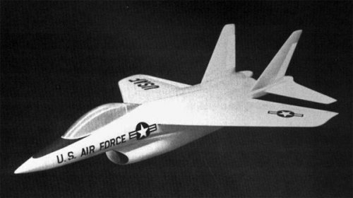
This is identified by Bill Gunston as "205C" and Jay Miller as "785 variation".
 

Attachments

  • 205C Model.jpg
    205C Model.jpg
    50.1 KB · Views: 514
Sources:

L.E. Surber and Lt. C.P. Robinson, Survey of Inlet Development for Supersonic Tactical Aircraft AIAA Paper 83-1164

C. W. Smith, J. N. Ralston, and H. W. Mann (General Dynamics), Aerodynamic Characteristics of Forebody and Nose Strakes Based on F-16 Wind Tunnel Test Experience Volume I: Summary and Analysis NASA Contractor Report 3053 1979

J. K. Buckner, P. W. Hill, and David Benepe (General Dynamics) Aerodynamic Design Evolution of the YF-16 AIAA Paper
74-935

Jay Miller
 
Sundog said:
In your first post, the third image down,

lightweight-fighter-twin-engine-jpg.11334


put a VG wing on it and it looks like the pic of the model OrionBlamBlam had on his website for a long time looking for identification.

If so, then it was one of General Dynamics FX studies.
 
Last edited:
BTW: any additions / clarifications to the early FX / ADF projects stuff are welcome. I think the later stuff is pretty complete, but the early designs are still somewhat hazy.
 
overscan said:
To show the vast number of different versions studied, here are some of the different inlet designs considered at different points, and then a table that shows all the different types of strake, wing, tail and inlet combinations wind tunnel tested.

Do you know at which time this studies were done? I guess GD expected that the USAF would ask for more than Mach 2 (which they did much too often). This illustrates very well than variable inlet is really necessary above Mach 1.8 (if your engine is in general powerful enough).
 
I keep thinking that the fully variable inlet would look good on the original F-16XL proposal which used a standard F-16 horicontal tail as an all-moving vertical tail.
 
Slightly better version of the 786 pic. Completely wrongly labelled as Model 404, and contrasted to Model 205C supposedly as the actual F-16 design, which is wrong (but marks the second appearance of "205C" as a designation).

Source:

Robert C Stern, Warbirds Illustrated 017 America's Fighters of the 1980s, Arms & Armour Press.
 

Attachments

  • 786.jpg
    786.jpg
    47.7 KB · Views: 1,959
This illustrates very well than variable inlet is really necessary above Mach 1.8 (if your engine is in general powerful enough).

That's true if you are using 1970's era technology. It isn't necessarily true using modern technology. The YF-22, YF-23, and F-22 all have fixed inlets and all were capable of speeds beyond Mach 2. For one thing, they are using 3D not 2D shock structures, and there are other technologies, such as using porous materials/fluidic controls within the inlets as well to aid in modern inlet operation/performance.
 
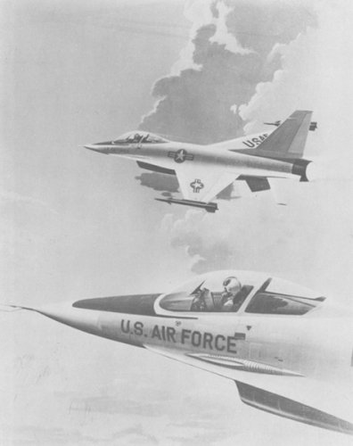
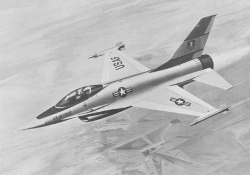
Early F-16 artists impressions from General Dynamics

Source:

Bill Holder & William Siuru, General Dynamics F-16 (Aero Publishers 1976)
 

Attachments

  • Early-F-16.jpg
    Early-F-16.jpg
    59.1 KB · Views: 1,886
  • Early-F-16-1.jpg
    Early-F-16-1.jpg
    63.4 KB · Views: 1,866
Added additional drawing of 401F-10A and a strake design tested on 785.

Source:
High Angle of Attack Aerodynamics AGARD-CP-247
http://stinet.dtic.mil/cgi-bin/GetTRDoc?AD=ADA067323&Location=U2&doc=GetTRDoc.pdf
 

Attachments

  • 785Strake.jpg
    785Strake.jpg
    48.4 KB · Views: 1,652
  • 401F10A.jpg
    401F10A.jpg
    60.9 KB · Views: 3,656
Moved GD/Vought Model 1600 stuff to VFAX topic here:

http://www.secretprojects.co.uk/forum/index.php/topic,1326
 
overscan said:
This is identified by Bill Gunston as "205C" and Jay Miller as "785 variation".

General Dynamics designations have a way of driving me crazy...
Could it be that 205C, 785 and all the 401x designations are simply variations of a basic "205" model? (as in 205-785, 205-401F...)
That would make a lot of sense since the last major design effort from GD's Convair division was the Model 200...


overscan said:
Moved GD/Vought Model 1600 stuff to VFAX topic.

Cool! But a link to the other topic from this here thread would be nice...
 
I don't think so, pretty sure it was just Model 401 and Model 785/786. And thats Forth Worth. GD San Diego's design for LWF was Model 18.

I added a link above to the VFAX/NACF topic.
 
overscan said:
To show the vast number of different versions studied, here are some of the different inlet designs considered at different points, and then a table that shows all the different types of strake, wing, tail and inlet combinations wind tunnel tested.
In colour.
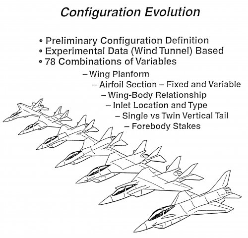
Image from Harry Hillaker's presentation on the development of the lightweight fighter shows the various configurations studied to come up with the optimum design of what became the F-16.
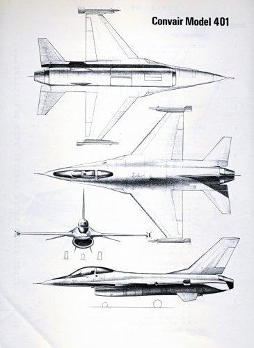
Convair (later General Dynamics) Model 401 with small canards on the strake. :eek:
Model 401 was the title of the aircraft General Dynamics presented as a response to the lightweight fighter request for proposals. Note the small canards on the strake.

Source: http://www.codeonemagazine.com/gallery_slideshow.html?item_id=24
 

Attachments

  • 02_YF16_evolution_1267828237_5060.JPG
    02_YF16_evolution_1267828237_5060.JPG
    329.2 KB · Views: 701
  • 03_Model_401_1267828237_5978.JPG
    03_Model_401_1267828237_5978.JPG
    260.2 KB · Views: 948
from

INTRODUCTION TO AERONAUTICS: A DESIGN PERSPECTIVE (see the original article for more illustrations)
CHAPTER 9: CASE STUDIES AND FUTURE AIRCRAFT DESIGNS

9.4 CASE STUDY #3: THE EVOLUTION OF THE F-16

The Lockheed-Martin F-16 Fighting Falcon multi-role tactical fighter must be regarded as one of the must successful and prolific (and certainly one of the most esthetically pleasing) jet fighter aircraft of the post-Vietnam War period. Its design evolution is an interesting one, because it was developed as a light-weight air-to-air fighter (a replacement for the F-5) but went into service as a medium-weight multi-role fighter (a replacement for the F-4). Its further development into the F-16XL deep-interdiction aircraft (a replacement for the F-111) is also discussed.

As stated by Bradley 9: “ The design of tactical military aircraft presents quite a challenge to the aerodynamicist because of the vast spectrum of operational requirements encompassed by today’s military scenario. The designer is faced with a multitude of design points throughout the subsonic-supersonic flow regimes plus many off-design constraints that call for imaginative approaches and compromises. Transonic design objectives are often made more difficult by restraints imposed by subsonic and supersonic requirements. For example, wings designed for efficient transonic cruise and maneuver must also have the capability to accelerate rapidly to supersonic speeds and exhibit efficient performance in that regime.”

Bradley continues: “The design problem is further complicated by the fact that the weapon systems of today are required to fill multiple roles. For example, an aircraft designed to fill the basic air superiority role is often used for air-to-ground support, strike penetration, or intercept missions. Thus, carriage and delivery of ordinance and carriage of external fuel present additional key considerations for the aerodynamicist. The resulting aircraft flowfield environment encompasses a complex mixture of interacting flows.”

“For example, the need for rapid acceleration to supersonic flight and efficient supersonic cruise calls for thin wing sections with relatively high sweep and with camber that is designed to trim out the aft ac movement at supersonic flight. However, these requirements are contrary to those requirements for efficient transonic maneuver, where the designer would prefer to have thicker wing sections designed with camber for high CL operation and a high-aspect-ratio planform to provide a good transonic drag polar.”

Harry Hillaker, who was the Chief Project Engineer on the YF-16 and Vice President and Deputy Program Director of the F-16, began10 the plane’s design process by clearly defining the problem and collecting data. Examination of results from air-to-air combat over Southeast Asia/Vietnam revealed that aircraft in the U. S. inventory had only marginal success over their opponents. From 1965-1968, engineers at General Dynamics in Fort Worth examined the data from the Southeast Asian conflict to determine what parameters provided an edge in air-to-air combat. Wing loadings, thrust loadings, control issues, g-tolerances for the pilot, and empty-weight fraction were identified as key parameters in air-to-air combat. Since these studies were focused on technology, there were no configuration designs.

Hillaker continued: “From 1969-1971, an extensive wind-tunnel program was conducted in which data were obtained on a wide variety of configurations over a range of free-stream test conditions and angles of attack.” As shown in the sketches of Fig. 9.12, configuration variables included wing planforms, airfoil sections, wing-body relationships, inlet locations, horizontal and vertical tail configurations, and forebody strakes. Buckner et al11 reported:

“The 1969-1970 period produced technology studies in four areas very important to air combat maneuvering fighter design:

1. Project Tailormate (1969,1970) - an experimental study of a wide variety of inlet types and locations on typical fighter designs with the goal of maintaining low distortion and high-pressure recovery over wide ranges of angle of attack and sideslip. The YF-16 inlet location is largely a result of the experience gained in this work.
2. Wing Mounted Roll Control Devices for Transonic, High-Light (sic) Conditions (1969) - a study of a variety of leading- and trailing-edge devices for roll control in the combat Mach number and high-angle-of-attack range.
3. Aerodynamic Contouring of a Wing-Body Design for an Advanced Air-Superiority Fighter (1970) - an add-on to the roll-control study, which produced analytical information on a blended wing-body design. This experience was helpful in the later development of the YF-16 overall planform and blended cross-section concept.
4. Buffet Studies (1969-1970) - a series of efforts producing new knowledge and methodology on the phenomenon of increased buffet with increasing angle of attack. The methodology, in turn, allowed the YF-16 to be designed for buffet intensity to be mild enough to permit tracking at essentially any angle of attack the pilot can command in the combat arena.

The above studies produced knowledge that was brought to bear on the configuration studies, specifically for the development of a lightweight low-cost fighter, accomplished in 1970, 71.”

The lightweight, low-cost fighter configuration studies intensified when a new set of guidelines were defined for application to combat scenarios in Europe. Hillaker 10 noted: “These mission rules included a 525 nautical mile (nm) radius, four turns at 0.9M at 30,000 feet, accelerate from 0.8M to 1.6M, three turns at 1.2M at 30,000 feet, and pull a four-g sustained turn at 0.8M at 40,000 feet. Furthermore, the aircraft had to demonstrate operability both for the U. S. Air Force and its NATO allies.”

As noted by Buckner et al: “The YF-16 really got its start, then, as a result of the ‘in-house’ studies initiated in late 1970 in response to the new mission rules. .. Major emphasis was placed on achieving flight and configuration characteristics that would contribute directly to the air-to-air kill potential in the combat arena -- specifically maximizing maneuver/energy potential and eliminating aerodynamic anomalies up to the maneuver angle-of-attack limits.” Buckner and Webb 12 reported: “Examples of the ‘design to cost’ in the case of the YF-16 aerodynamic features are (1) a single engine, eliminating the complex question of what to do between the nozzles, (2) an empennage/nozzle integrated design, devoid of adverse interference, (3) a single vertical tail tucked in safely between the forebody vortices, (4) a simple underslung, open-nosed inlet with no complex moving parts, (5) a thin-wing airfoil with only slight camber, minimizing the question of Reynolds number effects on transonic shock locations, and (6) simple trailing-edge ailerons. All of these features reduced the cost through virtual elimination of design changes in the refinement stage after contract go-ahead and through simplification of the task required to fully define the vehicle aerodynamics.” In 1972, aerodynamic data were obtained over a wide range of Mach number, of Reynolds number, and of angle of attack. The ranges of these variables, as taken from Reference 9, are reproduced in Fig. 9.13.

Buckner et al.11 reported that: “From these data it is obvious that the taper ratio () should be as low as practical, consistent with reasonable tip-chord structural thickness and early tip-stall configurations. The final selection was a taper ratio of 0.227. The start combat weight is lowest at a wing aspect ratio of 3.0, the final selected value, and is relatively independent of wing sweep in the range of 35 to 40 degrees. The greater wing sweep is beneficial to the supersonic performance, giving reduced acceleration time and increased turn rate. Some penalty in aircraft size is noted as the wing sweep is increased to 45 degrees, and the higher-sweep wings are more prone to have aileron reversal because of aeroelastic effects. As a result, wind tunnel tests were limited to sweep angles between 35 and 45 degrees. Perturbation of wing thickness ratio (t/c) indicates a lighter weight airplane with a thicker wing, but supersonic maneuverability improve with thinner wings. The desire to achieve a balance in subsonic and supersonic maneuver capability dictated selection of as thin a wing as practical (t/c = 0.04), consistent with flutter and aileron reversal considerations.”

Bradley notes that: “ The tactical military aircraft design problem is made more difficult by the supersonic acceleration requirement. The wings must be as thin as structurally feasible to reduce drag, but fixed camber suitable for optimum transonic maneuver is not practical because of supersonic camber drag. An obvious solution is a smoothly varying wing camber design. However, structural and actuation system weights prove to be prohibitive for thin wings. Simple leading edge and trailing edge flaps often prove to be the most practical compromise for high-performance, multiple design point configurations.”

“The extreme possibilities are apparent. One may design a wing with optimized transonic maneuver camber and twist and attempt to decamber the wing with simple flaps for supersonic flight. On the other hand, one may design the wing with no camber or with a mild supersonic camber and attempt to obtain transonic maneuver with simple flaps.”

Even though the designer has worked carefully to design a wing for attached flow and to optimize its performance, there are points in the sustained and instantaneous maneuver regimes where the flowfield contains extensive regions of separated flow. The manner in which the flow separates will strongly affect the vehicle’s drag and its controllability at the higher values of the lift coefficient. For many designs, strakes or leading-edge extension devices are used to provide a controlled separated flow. Controlled vortex flow can then be integrated with the variable camber devices on the wing surface to provide satisfactory high-lift, stability and control, and buffet characteristics. The resulting flowfield is a complex one, combining attached flows over portions of the wing with the vortex flow from the strake. See Figure 9.14.

One of the questions addressed by the designers of the Lightweight Fighter was single vertical tail versus twin-tailed configurations. See Fig. 9.10. NASA data available at this time indicated advantages of the twin-tailed configurations. However, as noted by Hillaker 10, The NASA data were limited to angles of attack of 15o, or less. Buckner et al.11 noted: “To the dismay of the design team, however, the directional stability characteristics of the twin-vertical-tailed 401F-0 configuration were not as expected. In fact, a severe loss of directional stability occurred at moderate-to-high angles of attack.... Analysis of oil flow visualization photographs led to the belief that forebody flow separations and the interaction of the resulting vortices with the wing and vertical tail flow fields were major causes of the stability problem.”

Modifications were made to delay forebody separation to higher angles of attack. Buckner et al 11 reported: “It was more difficult to make the twin-tail configurations satisfactory compared to the single vertical tail configurations (in addition, some combinations of angle of attack and sideslip produced visible buffeting of the twin tails). Beneficial effects on the directional stability derivatives were noted when relatively small highly swept ‘vortex generators’ (strakes) were located on the maximum half-breadth of the forebody.”

“At this point, NASA Langley Research Center aerodynamicists were consulted and they suggested that the lift of the wide forebody could be increased by sharpening the leading edge to strengthen the vortices rather than weaken them as our earlier attempts had done. The point was that forebody separation is inevitable at very high angle of attack; therefore, the lift advantages offered by sharp leading edges should be exploited. This also would allow the forebody vortices to dominate and stabilize the high-angle-of-attack flow field over the entire aircraft, improving, even, the flow over the outboard wing panels.”

Once the YF-16 was in the flight-test program with the YF-17, it was no longer called the Lightweight Fighter. It was called the Air Combat Fighter (ACF). Orders for the ACF, the F-16, came in 1975. The first operational units were formed in 1978. In the late 1970s, production versions of the F-16 were quickly modified to add a full radar capability, to add hard points to accommodate the ability to handle air-to-ground capability, and to increase the combat radius to 725 nautical miles. Thus, the aircraft had become a true multi-role fighter.

Bradley notes: “Perhaps the greatest irony for the tactical aircraft designer results from the fact that an aircraft designed to be the ultimate in aerodynamic efficiency throughout a performance spectrum is often used as a ‘truck’ to deliver armaments. Aircraft that are designed in a clean configuration are often used operationally to carry an assortment of pylons, racks, missiles, fuel tanks, bombs, designator seeker pods, launchers, dispensers, and antennas that are attached to the configuration at any conceivable location.”

“The carriage drag of the stores is often of the same order of magnitude as the total minimum drag of the aircraft itself. For example, the minimum drag of the F-16 aircraft is compared in Fig. 9.15 with and without the air-to-ground weapons load. It is readily seen that the store drags themselves present as large a problem to the aircraft designer as the drag of the clean configuration. Store carriage on modern tactical aircraft is extremely important, particularly as one approaches the transonic regime, where the interference effects of the stores and pylons are highest and most detrimental to performance.”

Bradley continues: “ Not only must external stores be carried efficiently by tactical aircraft, but they must release cleanly and follow a predictable trajectory through the vehicle’s flowfield. The store trajectory is governed by the highly unsteady forces and moments acting on the store produced by the nonuniform flowfield about the configuration and the aerodynamic characteristics and motions of the store itself. The problem is complicated by realistic combat requirements for jettison or launch at maneuver conditions and multiple release conditions where the weapons must not ‘fly’ into one another.”

Military aircraft of the future will have added emphasis on store carriage and release early in the design process. Some possible concepts for weapons carriage are contrasted in Table 9.4.

Bradley presented wind-tunnel measurements that compared the drag for conformal carriage versus conventional installations of MK-82 bombs. As shown in Fig. 9.16, conformal carriage permits one to carry 14 MK-82 bombs at substantially less drag than a 12 MK-82 pylon/multiple bomb rack mounting. Bradley noted: “Significant benefits for the conformal carriage approach, in addition to increased range, are realized: increased number of weapons and carriage flexibility; increased penetration speed; higher maneuver limits; and improved supersonic persistence. Lateral directional stability is actually improved with the weapons on.”

Hillaker noted that in 1974, General Dynamics embarked on a Supersonic Cruise and Maneuver Program (SCAMP) to develop a supersonic cruise derivative of the F-16. The “supercruiser” concept envisioned optimization at supersonic cruise lift conditions so that sustained cruise speeds on dry power (nonafterburner power) could be achieved in the Mach 1.2 to 1.3 speed range. Trade-offs to the aerodynamics required for supersonic cruise, subsonic cruise, and maneuvering flight were explored. The goal was to arrive at a design that would offer at least a 50% increase in the supersonic lift-to-drag ratio (L/D), that would retain a high subsonic L/D ratio, and that would provide the level of maneuverability of a fighter.
 

Attachments

  • lwf_evolution.jpg
    lwf_evolution.jpg
    1,014.4 KB · Views: 947
The F-16 Story - AFSC STAFF FILM REPORT 257 (1977) United States Air Force
BRIGADIER GENERAL JAMES ABRAHAMSON, F-16 PROGRAM DIRECTOR, PRESENTS THE F-16 FIGHTER. HE DESCRIBES THE UNIQUE COMPETITIVE ORIGINS OF THE PROGRAM AND THE MULTI-NATION ASPECTS OF THE CONSORTIUM FORMED TO PRODUCE IT. USING A MODEL AND ENGINEERING FILM, HE DETAILS THE AIR-TO-AIR AND AIR-TO- GROUND ROLES OF THIS LOW-COST, LIGHT WEIGHT ADDITION TO NATO AND THE US AIR FORCE. HE DISCUSSES THE UNUSUAL FEATURES, OUTSTANDING CAPABILITIES, AND ECONOMIC AND MILITARY VALUE OF THIS ADVANCED TECHNLOGY WEAPONS SYSTEM.
 
Last edited by a moderator:
1).This artist pencil drawing of Configuration 401F-5 was one in a series of designs that led to what became the Lightweight Fighter, or LWF. This eventually led to the F-16. Note the small canards on the fuselage below the canopy.


2).This artist pencil drawing, dated 26 November 1971, was one in a series of designs that led to what became the Lightweight Fighter. This eventually led to the F-16. Note the placement options for the horizontal tails.

UPD Replaced with hi-res variants from CodeOne Spotlight Photos page. There are even more interesting and rare F-16 memorabilia there
http://www.codeonemagazine.com/gallery_slideshow.html?item_id=2098
 

Attachments

  • 2012_F16_Evol_401F_5_sketch_1267828237_8567.jpg
    2012_F16_Evol_401F_5_sketch_1267828237_8567.jpg
    63.3 KB · Views: 509
  • 2012_LWF_Design_Study_1267828237_7618.jpg
    2012_LWF_Design_Study_1267828237_7618.jpg
    78.4 KB · Views: 563
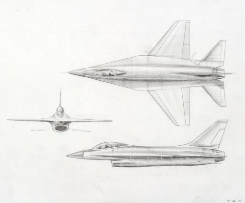
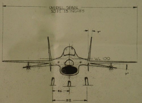
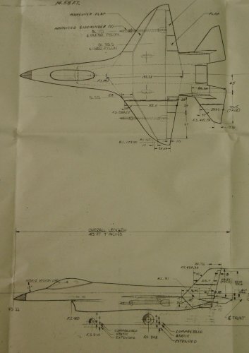
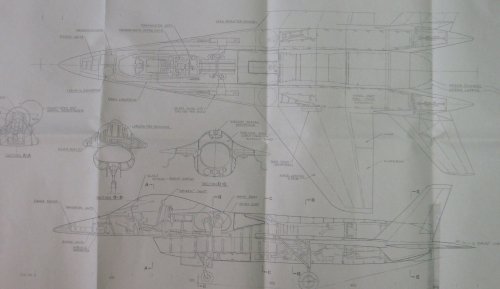
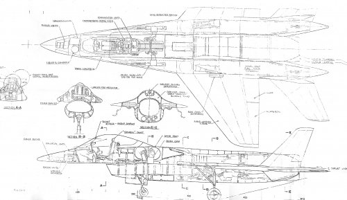
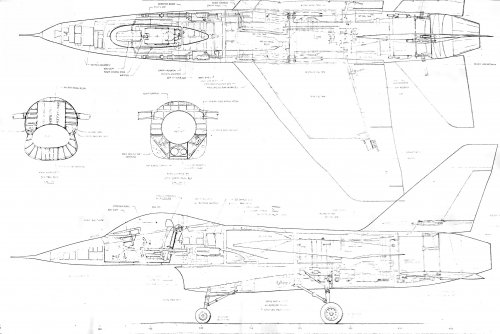
Here are a couple of drawings of the 401 twin tail design. I apologize for the quality, the drawings were large and folded. I have a couple of other drawings that I'll post a little later.
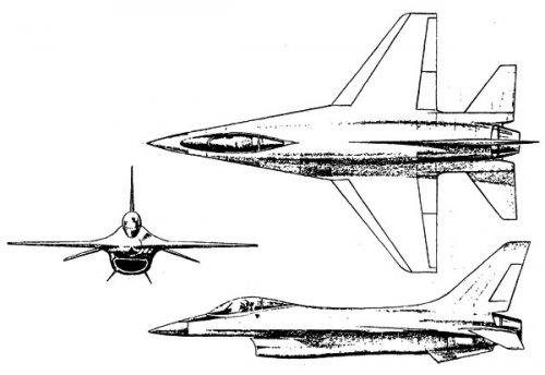
 

Attachments

  • 401.jpg
    401.jpg
    314.2 KB · Views: 1,353
  • 401 2.jpg
    401 2.jpg
    398.8 KB · Views: 1,397
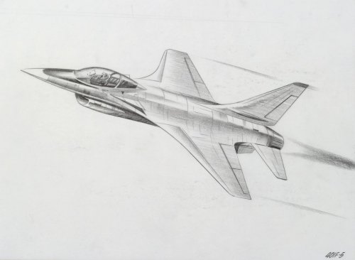
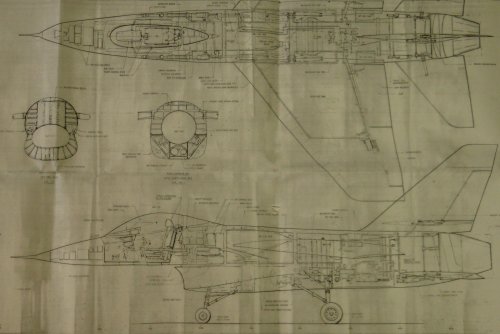
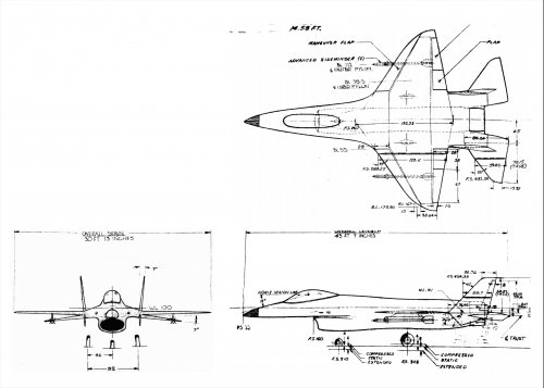
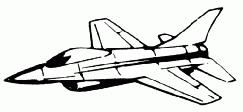
Couple more drawings. One of the twin tail, looks a little different. The other is titled Alternate ADF with single tail. Again sorry about the quality, I actually had to lay these out on the floor and snap photos of them. Both were from the early 1970's, I'll go back and check the data block on the drawings and proivde more info a little later.
 

Attachments

  • 401C Advanced Day Fighter (1971).JPG
    401C Advanced Day Fighter (1971).JPG
    394.2 KB · Views: 1,240
  • GD 785 Alternate ADF Study.jpg
    GD 785 Alternate ADF Study.jpg
    478.3 KB · Views: 1,235
+10 thanks, some awesome sharing today :)


If you can get individual photos of small sections clearer, I can edit and stitch them together on the computer for you :)
 
Your first twin tail design posted is the original 401F.

The second twin tail design, I can't place yet. Swept tailplane is very distinctive.


Edit - just saw filename - its apparently "401C"
 
I'll try to get some better pics this weekend. Glad you like 'em.
 
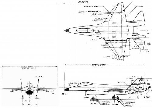
Quick edit. Can't quite get the front view to size to match.
 

Attachments

  • 401Full.jpg
    401Full.jpg
    464.7 KB · Views: 1,163
Not too much I can do with these ones.
 

Attachments

  • 401C Advanced Day Fighter (1971)ed.jpg
    401C Advanced Day Fighter (1971)ed.jpg
    604.8 KB · Views: 667
  • GD 785 Alternate ADF Study-ed.jpg
    GD 785 Alternate ADF Study-ed.jpg
    494.1 KB · Views: 670
PaulMM said:
Quick edit. Can't quite get the front view to size to match.

The front view isn't the problem, but the top view, which matches the length of the
side view, but not the span of the front view ! Looks like the precision of this drawing
isn't the best ...
 

Attachments

  • 401Full.jpg
    401Full.jpg
    389.5 KB · Views: 761
Nice drawing RAP and thanks to the "fixers" for the clean ups.

What else might you have?! ;D

Thanks! Mark
 

Please donate to support the forum.

Back
Top Bottom