A9 Amerika rocket

jetboy

SPACE,ROCKETS,MISSILES DOES,NT GET ANY BETTER.
Joined
1 April 2013
Messages
34
Reaction score
4
Hi,its my first post,im usually on Britmodeller,in the real space section,its a bit lonely at times?lol.I would like to get into a bit more scratchbuilding,and try and build some of the more unusual missiles,rockets,and space hardware.
Im currently trying to build all the saturn variants,built and unbuilt,but getting a sick of seeing black&white,paint jobs at the moment,back to post in hand,i thought you might want to see my recently finished A9,im currently just doing another version of this,

036_zpsd4908039.jpg


061_zps2d52fa8d.jpg


loads more if you want to see them,best wishes Don

sorry should have put these pics on,when i first posted,so heres some more


039_zps28b3bf5d.jpg


040_zps0643ad9f.jpg


041_zpse78846e8.jpg


042_zps40a62c26.jpg


043_zps66179f0c.jpg


the priming/filling


007_zps4bb7f629.jpg


008_zps9db9e311.jpg


Right chaps,it got us here,will it make it home

010_zpsb637fd71.jpg


fist design of camo

036_zps9ae4806b.jpg


037_zps4df66c71.jpg


053_zps99e1bd69.jpg


054_zpsaa9baad7.jpg


055_zpsca40894c.jpg


056_zpsa00a29ac.jpg

i made the mistake of varnishing over the canopy..Doh!

059_zpsf3abc938.jpg


060_zps9015fd38.jpg


061_zps2d52fa8d.jpg


038_zps30712246.jpg


this is the launch stand that comes with the kit,but this version doe,nt need this as it was designed,for in flight seperation,with something like this-the A9-A10-A11.

044_zps7e0a3dd8.jpg


A9-A10-A11-not started yet,but just mocked up to show you it,looking very much like a multi-stage Saturn/apollo,i wonder why?,,,,dont answer that,i was joking?

023_zps110a44e1.jpg


hope you like it,Best wishes Don
 
Assuming, for the moment, that the *manned* A-9 wasn't just a modern invention... why would it be camoflaged? It was an expendable ICBM, to be launched from a vast underground fortress. We don't camo ICBMs today. You could paint it hot pink with magnesium flares on the wingtips and loudspeakers blaring "La Cucaracha" at 300 decibels, it would have made no difference for those trying to intercept it.
 
Hi,thanks for reply,im only assuming here,but as the A9 was designed to go up,and then glide to target,and due to the date of design,no decent guidence available,so it had to have a pilot,who at least got it as far as the U.S coast?,who then had to point the projectile and then bale out to be rescued by a waiting u-boat,i presume,the vehicle would be observable and exposed during the time before impact,a bit different from V2,s which just dropped out of the Air,which were camo,ed,mainly because of the time it took to launch,in the open,as hardened bunkers werea fixed target,so not really secret?.The allie,s took the best option for these weapons,by targeting the supply infrastructure,so really limiting the impact[excuse the pun]that these weapons of the future posed,anyway thats my thoughts on it,sorry if its a bit of a ramble,but it was a glimpse of what was to come...possibly the simpler explanation would be ,,,it looked ucking mean and scary,i dont know? cheers Don
 
Orionblamblam said:
Assuming, for the moment, that the *manned* A-9 wasn't just a modern invention... why would it be camoflaged? It was an expendable ICBM, to be launched from a vast underground fortress. We don't camo ICBMs today. You could paint it hot pink with magnesium flares on the wingtips and loudspeakers blaring "La Cucaracha" at 300 decibels, it would have made no difference for those trying to intercept it.


That camouflaged stuff is a wide misunderstanding in operation of the V2 missile.
356px-Bundesarchiv_Bild_141-1879%2C_Rakete_V2_nach_Start.jpg

The latest A4 was used on mobil launcher an had to be camouflaged until launch.
So allot people believed the A9 had also to be camouflaged.
Bundesarchiv_Bild_146-1978-Anh.026-01%2C_Peenemünde%2C_V2_beim_Start.jpg

but it had look like this during R&D
and for the operational version would certainly look like this:
pained hot pink, with magnesium flares on the wingtips and loudspeakers blaring "La Cucaracha" at 300 decibels during launch... <just kidding, guys ;D>
 
jetboy said:
Hi,thanks for reply,im only assuming here,but as the A9 was designed to go up,and then glide to target,and due to the date of design,no decent guidence available,so it had to have a pilot,who at least got it as far as the U.S coast?

There is no evidence that the designers intended such a thing. All references that have so far been published about the A-9/A-10 from the wartime era indicate an unmanned ICBM over very large CEP.

,which were camo,ed,mainly because of the time it took to launch,in the open,as hardened bunkers werea fixed target,so not really secret?

The A-10 system would have been even more cumbersome than the Atlas rocket to get up and running. Launching an Atlas from some field just wasn't going to happen; neither was launching an A-10. It would have required a large, presumably heavily defended, emplacement. Remember, at the time the A-10 was actually designed and considered, the Germans pretty much *owned* France, and did not expect much in the way of effective Allied aerial bombardment.
 
It would be nice to know when the "manned A9" drawings appeared, during wartime or was some re-elaboration of 50's?


We know that the combination of A9/A10 was intended as a sort of today's ICBM forerunner, but around the "manned A9" myth there was some von Braun's statements or drawing? Or was someone closer to von Braun to mention such kind of missile?
 
There were a few drawings of a manned, winged V-2 published very shortly after the war. The one with closest to believable provenance was the well-known three-view of the stretched V-2 with stretched fuslelage, swept wings, landing gear and a ramjet. This appeared circa 1946 in a US Army report on Peenemunde, and appears to be a single-stage research vehicle. The "Manned A-9/A-10," however, does not seem to have appeared until the 1990's... as drafted by a member of this very forum. You know who you are...
 
You know who you are...

it was not me !
I swear i have nothing to do with this !


Back to A9/A10
I located a possibly production/launch underground bunker for this Project
Sonderbauvorhaben III or "S/III"
Between Mittelwerk V2 production site and V2 engine test stand Vorwerk
index.php


more on that HERE
http://www.secretprojects.co.uk/forum/index.php/topic,10740.msg123043.html#msg123043

By the way
Jetboy you really are talented Model builder !
 
Orionblamblam said:
There were a few drawings of a manned, winged V-2 published very shortly after the war. The one with closest to believable provenance was the well-known three-view of the stretched V-2 with stretched fuslelage, swept wings, landing gear and a ramjet. This appeared circa 1946 in a US Army report on Peenemunde, and appears to be a single-stage research vehicle. The "Manned A-9/A-10," however, does not seem to have appeared until the 1990's... as drafted by a member of this very forum. You know who you are...
HI,intresting thread developing,i would answer but,lets be honest its a Model,the original question was why would it be camoe,d,well i thought i gave a very satisfactory reply to that,and your latest question i dont understand,because von braun himself said,that the plans for the,a4b,project plans,showed a pressurized cockpit in place of a warhead,obviosly planning to land it,as it had a tricyle undercarriage,and goes on to say if the A9 dart winged varient were to be mounted on a secound stage booster it would become a supersonic plane,capable of crossing the atlantic,with the A10 booster actually being in concept since 1936,they had not thought much beyond that at the time,but it was mooted that with,a further booster possibly designated A11,and with improved mass ratio,and improved propellant it was feasible to put a piloted A9 in orbit,this was from a book of 1981,fair enough there is no warhead mentioned?,but certainly a pilot,i still like the model though,lolcheers Don
 
Michel Van said:
You know who you are...

it was not me !
I swear i have nothing to do with this !


Back to A9/A10
I located a possibly production/launch underground bunker for this Project
Sonderbauvorhaben III or "S/III"
Between Mittelwerk V2 production site and V2 engine test stand Vorwerk
index.php


more on that HERE
http://www.secretprojects.co.uk/forum/index.php/topic,10740.msg123043.html#msg123043

By the way
Jetboy you really are talented Model builder !
Hi Mv, no not really,but i do love the subject of rockets,missiles,.space hardware,would love there to be more models available,,of the more obscure stuff,i think having a physical object,instead of paper/pixel,gives the subject more of appeal,to me.I would love to be able to scratch build,some missiles, especially the subject,s no one else does,i may try soon,before i get too old to bother, antyway thanks for looking and commenting,its the only way to learn...off other people.cheers Don
 
jetboy said:
because von braun himself said,that the plans for the,a4b,project plans,showed a pressurized cockpit in place of a warhead,obviosly planning to land it,as it had a tricyle undercarriage

Yes, that's the single-stage research vehicle. Sort of like the X-15. No weapons potential, as it had no warhead.
 
hi,thanks for the pics,btw is that the annigrand model,...just love this site,its got loads of g**d s**t,on all the subjects,i like,sorry i digress ,yes thanks for reply..cheers Don
 
Assuming, for the moment, that the *manned* A-9 wasn't just a modern invention... why would it be camoflaged?
Hmmm... I have no idea, what was to be A 9 terminal velocity, but the A 4b was to be slow when reaching its target. It was estimated, A 4b terminal velocity, after long gliding, was to be just 360 km/h - slow enough to be intercepted by a fighter.

Orionblamblam said:
The "Manned A-9/A-10," however, does not seem to have appeared until the 1990's... as drafted by a member of this very forum. You know who you are...
Do you mean Mr. J.M.? B)
 
During this years holidays, I read "Die Rakete und das Reich" by Michael J. Neufeld, describing the
development of rockets in Germany. Very interesting reading and good researched, to my opinion.
A reason for many V2 failures, was the still unknown supersonic flight regime. Instead of doing more
basic research, the V2 was pressed into service with some beefing up of suspected weak points, without
rectifying the real problems. Hard to imagine, that the A9 would have been blessed with a better starting
situation, not to mention the A9/A10. So, speculations about terminal velocity for all those later types
probably are quite academic, at best !
 
Well, by the and of 1944 most (if not all) structural problems with the A 4 were already identified and mostly cured. A winged variant as the A 4 b or A 9 presented, of course, a number of another problems, connected with its winged layout and gliding flight profile - stability at sub- and supersonic speeds, new steering system, range exceeding available radio guidance horizon, continuous power supply during the whole flight, strengthened construction due to increased lateral forces etc...
But ten A 4 bs were already under construction then, two were actually launched in December 1944 and January 1945 - so calculating the terminal velocity was not a pure speculation for sure. :)
 
Honestly, that there still were aerodynamical problems was new for me, I had thought, that the aerodynamics
of the V2 were understood quite well, as its shape was more or less that of the well known artillery shell. But, as is
said in the mentioned book, problems arose due to steering the rocket, something, that hadn't been done with shells
before. The uneven aerodynamic loads often resulted in "Luftzerlegern" (disassembly in the air), which occured even
late in the war. A solution would have needed changes in the flight system, but only some structural changes were made.
So, the number of failures was reduced, but the principal problem wasn't solved. That's from my memory, what I read,
but I'll try to get this book again.
Nevertheless, the most interesting point for me wasn't what the V2 or its successors achieved, or could have achieved, but what
the German military industry could have achieved without it. Although a much smaller project, than the US Manhattan Project,
it nevertheless was a constant drain of resources of a scale, that brought severe limitations for all other services. So, in a certain
sense maybe, it could be called an allied wonderweapon !
 
There were problems with the winged A 4 b - wind tunnel tests revealed, the swept wing variant, we know, became unstable around Mach 0.85 and so a straight wing was proposed for the later prototypes in the end of 1944.
I have no idea if much could be done in the flight system to avoid Luftzerlegern in a purely ballistic missile. LZs were occurring very low, very few kilometres above the ground (even 1-1.5 km according to Wegener), and it seems that structural improvements to the tank and steering sections cured the problem pretty effectively (if not completely). Could a different flight profile alone eliminate LZs?
 
The "Manned A-9/A-10," however, does not seem to have appeared until the 1990's
Do you mean appeared as if it had been a real project/proposal? Doesn’t your 2003 APR publication of Gerd de Beek’s sketch show that the concept existed, at least post war? (not necessarily as an Amerika rocket)
 
Do you mean appeared as if it had been a real project/proposal? Doesn’t your 2003 APR publication of Gerd de Beek’s sketch show that the concept existed, at least post war? (not necessarily as an Amerika rocket)

What I (probably) meant way back when was *this* specific A-9/A-10, with the strake-like A-9 wings and the narrow-bodied A-10.
 
Too many assumptions. The manned A-9, the A-9b, sat atop the A-10 booster. Though there are no known photos of them, further developments were built, designated A-11 through A-14. There is a declassified CIOS report about these, but even it is scant on details. As some may know, Walter Dornberger became a consultant to the Bell Aircraft Company. One account has Dornberger showing Lawrence D. Bell photos of advanced rockets and even motion picture film. I am researching this.

There is the fiction that the Germans were unaware of hypersonics and atmospheric heating. Early V-2s were detonating in the atmosphere shortly after launch. The Germans solved the problem by adding glass wool insulation. A Mach 10 wind tunnel was found at Peenemünde. It was installed in the United States in 1947.

The space plane was a German wartime concept. There was also the space station. These were revealed right after the war. In 1950, a two volume set titled German Aviation Medicine: World War II by the USAF Surgeon General was released. It showed spacesuit concepts in photos. During the war, the Germans designed a high (full) pressure suit or Hochdruckanzug. Photos exist of a pilot wearing it in the cockpit of the Horten Ho IX. The view was limited to the upper torso. A little bit more can be seen in a cover painting on the book Natter - Manned Missile of the Third Reich by Brett Gooden. The helmets are the same, but different helmet designs were tried. Neither shows the oxygen connector section that attaches to the front. This suit was made by the Draeger company (Drägerwerke).
Hello.
I am currently researching the A9/A10 rocket system and you have a lot of new information to me. As far as I am aware, the A9/A10 were never built to begin with, the closest they came was to constructing the launchpads and the hypersonic wind tunnel. Blueprints exist of the A9, A10, A11 and A12 rockets, however I could not find anything on the A13 and A14. Do you have any information and blueprints of them? Also, do you have any images of the said spacesuit concepts?
Thank you.

Hello,

I have no images I can post.

CIOS Report XXXII-125 German Guided Missile Research. It mentions rockets other than the V-2 or A-4 (German designation). "A-11, A-12, A-13, A-14 further development models of the A9/10 with 3500 mile range. Long-range rockets for attacks on the United States. A-15: This probably never left the drawing board."

There were launch pads but these advanced rockets were held in underground missile siloes.
 
Hello.
I am currently researching the A9/A10 rocket system and you have a lot of new information to me. As far as I am aware, the A9/A10 were never built to begin with, the closest they came was to constructing the launchpads and the hypersonic wind tunnel. Blueprints exist of the A9, A10, A11 and A12 rockets, however I could not find anything on the A13 and A14. Do you have any information and blueprints of them? Also, do you have any images of the said spacesuit concepts?
Thank you.
The V2 missile reached a speed of 3,500 mph (5,632 Km/h-Mach 5.3) flying at 317,000 ft. By the time the rocket was plunging back through the stratosphere, the denser air began to slow down the rocket until it reached 2,237 mph (3,600 km/h) velocity of impact.

The very high kinetic energy with which the rocket came to earth could be transformed into aerodynamic drive by adding wings and larger air rudders. It was intended to glide after re-entry into dense atmosphere, trading speed for distance. On January 30, 1941, it was expected to reach an extended range of 885-1,207 miles (550-750 km). By the time. some wind tunnel tests were conducted with winged models of the V2 at the Zeppelin-Friedrichshafen research center. Seven scale models were used, with four different types of wings, under the denomination Gleiter (Glider).

The V13e, V14e and V14f (17-1-41) models were tested with Flossengeschoss (ogival delta) wings, the V12c (21-1-41) with 45 degrees swept wings, the V12f with scalloped triple delta wings and the V12a (21-1-41) with Trapezflügel (trapezoidal) wings.

Gleiter A5/V12c was selected as the V-2 aerodynamic successor and Gleiter A4/V13e as the second stage of the A10 intercontinental rocket system.

Aerodynamic tests conducted with both configurations showed that the swept wings became unstable around Mach 0.85 but the ogival delta provided better lift and solved the center of pressure displacing problem at supersonic speeds.

In February 1941, to prove the behavior of the swept wings at subsonic speeds, three A5 rockets were modified by Elektromechanische Werke GmbH (EMW) as Gleiter A5/V12c tests gliders.

On October 25, 1942, the V12c was carried to an altitude of 19,700 ft. by the Heinkel He 111 H-4 (NF + AB) modified bomber and released in ballistic flight, without propulsion unit, to test flight stability of the new steering control device. The V12c flew in straight glide and recovered by parachute.

In 1942 the project was re-named A7, but further development of winged rockets was stopped, between October 1942 and June 1944, to concentrate on war production of the V2. When the Allies advanced towards German border, following the Normandy invasion, all the V2 launch sites in France, Belgium and Holland had been lost and the extended-range rocket project was re-activated under the code name EMW A4b.

On October 10, 1944, they started modification of 16 V2 airframes into A4b winged rockets. The first prototype A4b G1, fitted with 45 degrees swept wings and standard tail surfaces, was launched from Peenemünde Test Stand X on December 1, 1944, but it was destroyed because of failures in the control system.

The second prototype (W.Nr.17543), with modified tail surfaces, was successfully launched on January 24, 1945. It attained a maximum speed of 2,700 mph (4,345 km/h-Mach 4.1) flying at 253,000 ft. but, after re-entry into the stratosphere, one of its wings could not withstand deceleration and the rocket was destroyed.

The A4b project was cancelled in favor of an entirely new weapon code-named A9.


EMW A5 technical data​

Type: aerodynamic tests rocket for the V2 development program, stabilizer span: 4.8 ft. (1.46 m), length: 19 ft. (5.83 m), maximum diameter: 2.8 ft. (0.86 m), estimated maximum speed: 1,243 mph (2,000 km/h), estimated ceiling: 39,360 ft. (12,000 m), estimated range: 11 miles (18 km), take-off weight: 1,987 lb. (900 kg), power plant: one Kummersdorf A-2 bi-propellant rocket with 1,500 peak thrust, propellants: A-Stoff (liquid oxygen at -183ºC) and M-Stoff (Methyl alcohol), pressurizer: nitrogen.


EMW A7 technical data​

Type: aerodynamic tests rocket for the A4b development program, wingspan: 8.59 ft. (2.62 m), stabilizer span: 5.7 ft. (1.75 m), length: 19.4 ft. (5.91 m), maximum diameter: 2.8 ft. (0.86 m), take-off weight: 2,207 lb. (1,000 kg), power plant: one Kummersdorf A-2 bi-propellant rocket motor with 1,500 kg peak thrust, propellants: A-Stoff (liquid oxygen at -183ºC) and M-Stoff (Methyl alcohol), pressurizer: nitrogen.


EMW A4b technical data​

Type: intermediate range boost-glide missile, airframe: steel structure with riveted steel plates cladding, power plant: one EMW bi-propellant rocket motor with 60,500 lb. (27,500 kg) peak thrust, propellants: 5,533 kg of A-Stoff and 4,173 kg of M-Stoff, pressurizers: 172 kg of T-Stoff (80 % Hydrogen Peroxide, 20 % Oxiquinoline) and Z-Stoff (watery solution of sodium or calcium), wingspan: 20.3 ft. (6.2 m), stabilizer span: 13 ft. (3.99 m), length: 46 ft. (14.03 m), maximum diameter: 5.5 ft. (1.8 m), take-off weight: 28,600 lb. (13,000 kg), estimated maximum speed: 2,700 mph (4,344 km/h-Mach 4.1), estimated ceiling: 311,600 ft. (95,000 m), estimated range: 373 miles (600 km).

The ballistic accuracy of the V2 depended on the range. During operations against London the average deviation was some 11 miles. To increase accuracy the rocket was controlled in the initial phase of its flight by two land-based ultra-short-wave transmitters HV-Gerät, intended to prevent the missile from diverging from its predetermined path.

Using radio guidance, it was expected to hit a target of 2.5 x 2.5 miles, but when the range exceeded the available beam horizon, a new steering system was needed.

Engineers believed that a manned A4b would have solved the guidance problem, because no suitable guidance method existed at the time.

The V2 rocket was conceived as a long-range artillery weapon to circumvent the Treaty of Versailles limitations. The entire rocket development and manufacturing program had been funded by the Oberkommando des Heeres (German Army high command) but the existence of a piloted version would require part of the program to depend on the Luftwaffe.

A piloted A4b had the precision of Reichenberg IV and greater destructive power but, unlike this one, could not be intercepted. Controlling this new weapons system, Göring acquired the ability to eliminate generals, kings, and politburo members and thus the opportunity to negotiate an honorable peace like in 1918.
 

Attachments

  • v.jpg
    v.jpg
    320.4 KB · Views: 2
  • vb.jpg
    vb.jpg
    379.3 KB · Views: 3
  • vv.jpg
    vv.jpg
    308.7 KB · Views: 4
  • vvv.jpg
    vvv.jpg
    182 KB · Views: 4
Post-2

In the autumn of 1943, Dr. Bodo Lafferentz proposed a plan to attack New York and Washington using V2 rockets launched 186 miles from the United States coast.

The Prüfstand XII project involved towing a V2 in a watertight container behind a U-boat Type IX D-2 and ten set up vertically in the water, by means of ballast tanks, prior to the missile launch.

Admiral Doenitz approved the idea; however, the plan was delayed by technical concerns until late 1944 at which time work began, at Vulkanwerft-Stettin facilities, on three large containers 105 ft. long, displacing 500 tons each.

It was expected that the new Type XXI submarines could tow up to three containers. Once on station, the U-boat crews would enter the container and fuel the V2, set the I-Gerät gyroscopic guidance system and open the launch hatch. The missile would be triggered from the submarine by remote control.

Deploying one V2 launch battery needed hundreds of troops, technical crews and about 275 specialized support vehicles with sophisticated ancillary devices.

The missile was not suitable for naval use. Before launch, it was necessary to perform a countdown of 90 minutes and a U-boat could not remain surfaced for so long near the U.S. coast.

In addition, the rocket was very vulnerable to corrosion, since testing determined that excessive storage time resulted in more failures.

There was also the problem of evaporation losses during storage of the T-Stoff and the super-cool liquid oxygen. It was realized that the decomposition rate of Hydrogen Peroxide would not last the 30 days of voyage to New York and the liquid oxygen would also be lost by evaporation as it couldn’t be kept in hermetic tanks.

The T-Stoff required to spin the V2 turbo-pumps was an extremely dangerous chemical to handle as it would react with all organic material producing spontaneous combustion, because of its extreme oxidizing potential. Hydrogen Peroxide is highly volatile, and the vapor can ignite or detonate depending of temperature and pressure.

During the development of the Type XVIII U-boat propulsion system, the Kriegsmarine had already encountered numerous problems with high-test peroxide (HTP) and did not want to repeat the experience.

To solve the V2 shortcomings, the new missile EMW A8 was designed to use nitric acid and Diesel oil propellants pressurized with nitrogen.

The A8 did not require the use of turbo pumps and ignition system because the hypergolic propellants spontaneously ignited when they came in contact which each other. Both liquids can be stored at room temperature.

The A8 was to have been derived from the V2, using an extended central section to contain a great number of propellants and with a new control surfaces configuration.

The work on this development as well as other guided missiles was stopped early in 1945 in favor of concentration on the V2, because of the critical condition of manpower and materials caused by the successful bombing raids of the Allies.


EMW A8 technical data​

Type: intermediate range ballistic missile, airframe: steel structure with riveted steel plates cladding, power plant: one EMW bi-propellant rocket motor with 75,700 lb. (34,337 kg) peak thrust and 90 seconds burning time, propellants: SV-Stoff (94% of nitric acid, 6% nitrogen dioxide) and Schweröl (Diesel oil), stabilizer span: 13 ft. (3.99 m), length: 54 ft. (16.46 m), maximum diameter: 5.5 ft. (1.8 m), take-off weight: 49,240 lb. (22,344 kg), estimated ballistic range: 300 miles (482 km).


In 1943 one winged version of the A8 was proposed to the RLM as high-altitude reconnaissance aircraft.

The new rocket plane, named EMW A6, was fitted with 61 degrees swept wings, pressurized cockpit, and ventral ramjet for extended range.

The radical wing was object of criticism by the Technisches Amt. Its main objection was based in the excessive landing speed of 280 mph estimated in the original project.

New wings with extended span and 45 degrees swept, and one drag parachute for landing on a conventional airfield were adopted, but the project was rejected.

The A6 would be launched vertically, and their powerful rocket motor would accelerate the aircraft to supersonic speed. After re-entry into the stratosphere and beginning the supersonic glide phase, the ramjet was ignited providing twenty minutes of cruise flight.


EMW A6 technical data​

Type: high-altitude reconnaissance airplane, airframe: steel structure with riveted steel plates cladding, power plant: one EMW bi-propellant rocket motor with 75,700 lb. (34,337 kg) peak thrust and 90 seconds burning time and one Lorin Strahlrohr ramjet of the Ta 183 class burning K1 heavy kerosene or liquid carbon disulphide, propellants: SV-Stoff and Schweröl, wing span: 33.3 ft. (10.15 m), length: 51.7 ft. (15.75 m), maximum diameter: 5.7 ft. (1.73 m),estimated maximum speed: 1,802 mph (2,900 km/h), estimated ceiling: 311,600 ft. (95,000 m), estimated range: 400 miles (644 km).
 

Attachments

  • b.jpg
    b.jpg
    314 KB · Views: 3
  • bb.jpg
    bb.jpg
    263.4 KB · Views: 3
  • bbb.jpg
    bbb.jpg
    298.2 KB · Views: 3
  • bbbb.jpg
    bbbb.jpg
    397.6 KB · Views: 3
  • bbbbb.jpg
    bbbbb.jpg
    246.2 KB · Views: 2
  • bbbbbb.jpg
    bbbbbb.jpg
    188.2 KB · Views: 2
Post-3

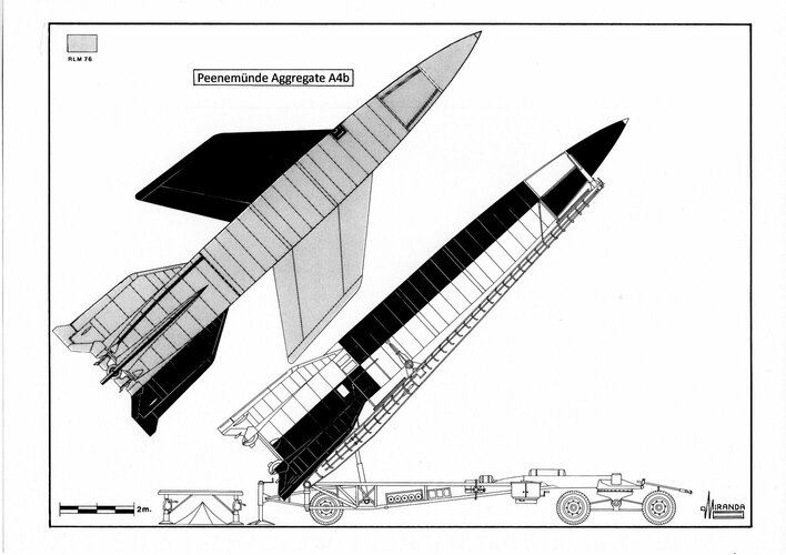
The A9 was designed in January 1941 as a V2 with ogival delta wings, 373 miles (600 km) extended range and 17 minutes flight time.

With this new weapon, the Wehrmacht would have the ability to attack Liverpool's industrial region from launch sites placed in northern France, but the A9 lacked enough range to reach Moscow by launching it from eastern Poland.

In October 1942, a proposal was made to launch it from a rocket catapult to increase the range by 1,000-1,300 km.

The Rheinmetall-Borsig catapult was made up of a launch ramp with 262 ft. (80 m) length and one rocket-sledge with 66,150 lb. (30,000 kg) peak thrust and was designed to launch a Fi 103 (V-1) flying bomb at 222.7 mph (360 km/h). But the Peenemünde engineers argued that the 15G-acceleration could damage the gyroscopic guidance system or disrupt the turbo pump operation.

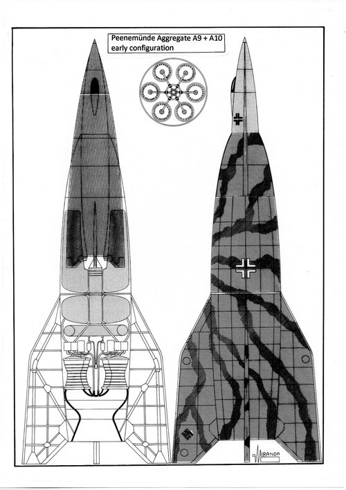
In March 1941, it was proposed to develop a two-rocket assembly with the A9 slotted into the top of a V2 boost stage, but the project was stopped in October 1942.

In late 1944 the development of two-rocket combination was resumed, under Projekt Amerika codename, with 5,000 km extended range.

To meet the specification the V-2 was replaced by a new rocket, with six V2 engines and 165 tons thrust, named A10.

The A9's rocket motor was based on the A8's technology and used Visol (mixture of vinyl-isobutyl ether with aniline) and S-Stoff-Salbei (96% nitric acid, 4% ferrous chloride) as propellants, with estimated peak thrust between 55,130-70,140 lb. (24,974-31,770 kg) and 68-115 seconds burn time, depending on the version and power of the turbo pump.

Early in 1945 the A10 project was modified with a new rocket motor, with 441,500 lb. (200,000 kg) peak thrust, that used as SV-Stoff (94% nitric acid, 6% nitrogen dioxide) and Visol as propellants.

The Projekt Amerika called for the construction of two launch sites, the first located in Brest-France should be used to attack New York, and the second, in Cape Roca-Portugal, to attack Pittsburg and Washington DC.

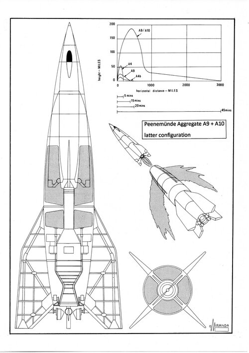
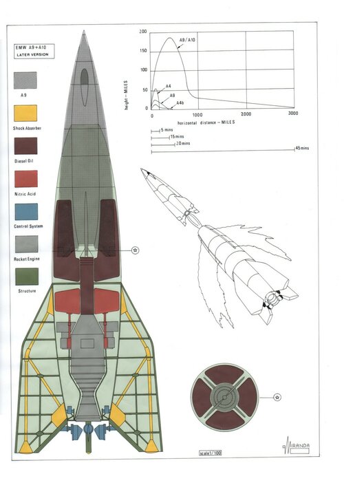
The A10 boost stage would burn for 55-60 seconds taking the A9 to 80,000 ft. altitude and was recovered by parachute. The upper stage would separate and burn its engine, accelerating up to 6,165 mph and climbing to 100 miles suborbital apogee, followed by a long powerless supersonic glide into the atmosphere.

When the missile descended to 246,000 ft. it would arc back up to 328,000 ft. secondary peak using the kinetic energy accumulated during the supersonic glide.

A 3,108 miles range was attained by means of repeated ‘skips’ into and out of the atmosphere and one terminal shallow glide towards its target.

The ‘skips’ were at the expense of the missile kinetic energy, each ‘skip’ being slower than the previous one.

It was expected that the A9 would be guided using the four stages of the Rheinland control method.

In the first stage the two-rocket assembly was to be steered, to the A9 separation, by Elsass radio control, with the aid of optical two-axis tracking device and one Rheingold radar set.

The second stage began after the A9 engine cut-off at 390 km altitude and 7,600 mph top speed. It used radar tracking, and the missile was still steered by means of the Kehlheim radio link system.

The third stage started when the A9 reached its maximum ceiling at 300 miles of the launch pad. The inertial navigation computer of the missile was coupled with one FuG 102 pulse modulated radio altimeter to perform scheduled skips on the flight plan. The A9 would ride up the radar beam of one Fu SE 75 Mannheim Riese radar set.

During the fourth stage, the missile would use the Elektra-Sonne long range navigation system and the FuG 126 Baldur automatic guidance system to make the necessary heading corrections, following a string of radio-beacons deployed by surfaced U-boats across of the Atlantic.

The terminal glide towards the target was to be steered by one rotating reticle infrared homing device developed by Wernher von Braun.

The intercontinental missile concept emerged far ahead of its time. Early in 1945 it was considered that existing guidance systems would not be accurate enough over a distance of 3,100 miles.

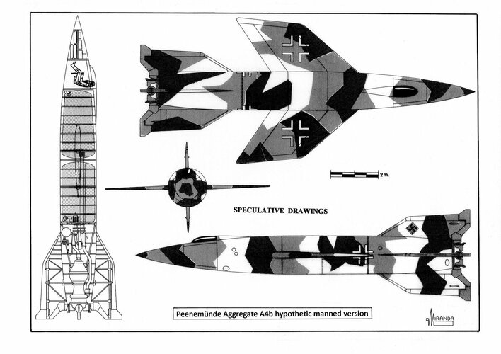
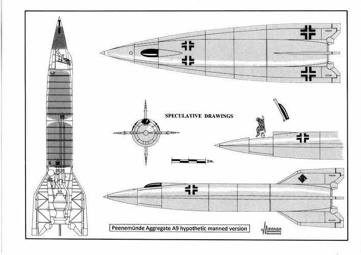
Engineers believed that a manned missile would have solved the problem of the added inaccuracies introduced by a long glide path, and could hit small targets with the accuracy of the Reichenberg IV.

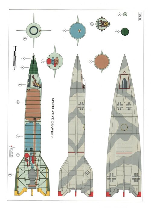
There were plans to develop a piloted A9 with pressurized cockpit, FuG 123 Truhe cartographic radar and Butterblüme infra-red ground-mapping device.


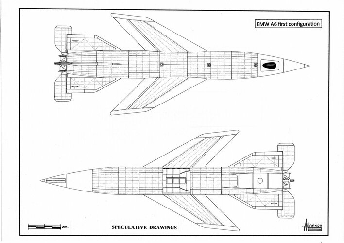
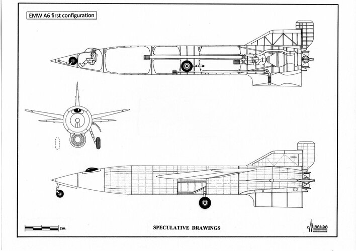
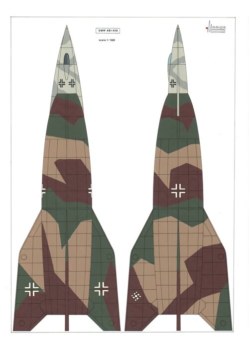
EMW A9 first configuration (1941) technical data​

Type: long range boost-glide missile, airframe: steel structure with riveted steel plates cladding, power plant: one EMW bi-propellant rocket motor with 60,500 lb. (27,500 kg) peak thrust, propellants: 5,533 kg of A-Stoff and 4,173 kg of M-Stoff, pressurizers: 172 kg of T-Stoff (80 % Hydrogen Peroxide, 20 % Oxiquinoline) and Z-Stoff (watery solution of sodium or calcium) actuating a turbo pump of 730 hp, wingspan: 11.6 ft. (3.58 m), length: 46 ft. (14.06 m), maximum diameter: 5.5 ft. (1.8 m), wing surface: 150 sq. ft. (13.5 sq. m.), take-off weight: 29,800 lb. (13,500 kg), estimated maximum speed: 1,740 mph (2,800 km/h), estimated ceiling: 316,818 ft. (96,000 m), estimated range: 373 miles (600 km), warhead: 2,150 lb. (975 kg) with 907 kg of Amatol 60/40.


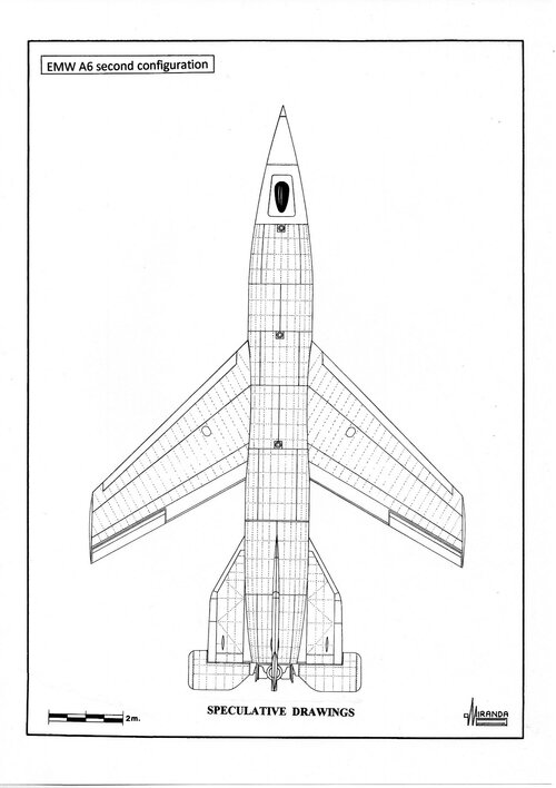
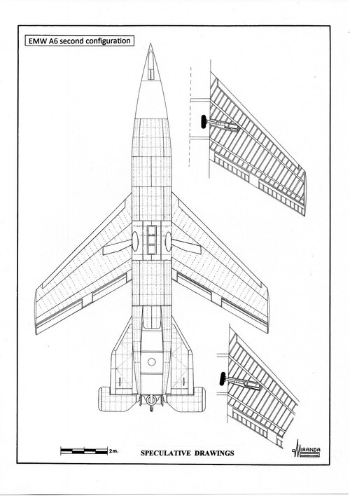
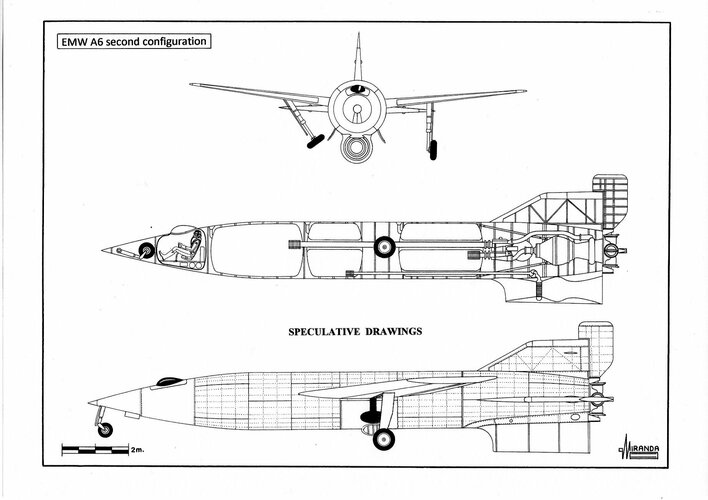
EMW A9 second configuration (1944) technical data​

Type: long range boost-glide missile, airframe: steel structure with riveted steel plates cladding, power plant: one EMW bi-propellant rocket motor with 55,130 lb. (24,974 kg) peak thrust, propellants: Visol and S-Stoff, pressurizers: T-Stoff and Z-Stoff, wingspan: 11.6 ft. (3.58 m), length: 46 ft. (14.06 m), maximum diameter: 5.5 ft. (1.8 m), wing surface: 150 sq. ft. (13.5 sq. m.), take-off weight: 35,850 lb. (16,260 kg), estimated maximum speed (with A10 booster): 6,165 mph (9,920 km/h- Mach 9.4), estimated ceiling: 524,800 ft. (160,000 m), estimated range: 3,180 miles (5,000 km), warhead: 2,150 lb. (975 kg) with 907 kg of Amatol 60/40.


EMW A9 third configuration (1945) technical data​

Type: long range boost-glide missile, airframe: steel structure with riveted steel plates cladding, power plant: one EMW bi-propellant rocket motor with 70,170 lb. (31,787 kg) peak thrust, propellants: Visol and SV-Stoff, pressurizers: T-Stoff and Z-Stoff, wingspan: 11.6 ft. (3.58 m), length: 46 ft. (14.06 m), maximum diameter: 5.5 ft. (1.8 m), wing surface: 150 sq. ft. (13.5 sq. m.), take-off weight: 35,850 lb. (16,260 kg), estimated maximum speed (with A10 booster): 6,835 mph (11,000 km/h), estimated ceiling: 574,000 ft. (175,000 m), estimated range: 3,418 miles (5,500 km), warhead: 2,150 lb. (975 kg) with 907 kg of Amatol 60/40.


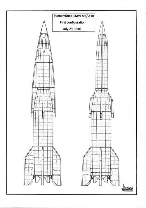
EMW A10 first configuration (1941) technical data​

Type: boost-stage for the A9 missile, airframe: steel structure with riveted steel plates cladding, power plant: one EMW bi-propellant rocket motor with 60,500 lb (27,500 kg) peak thrust, propellants: 5,533 kg of A-Stoff and 4,173 kg of M-Stoff, pressurizers: 172 kg of T-Stoff (80 % Hydrogen Peroxide, 20 % Oxyquinoline) and Z-Stoff (watery solution of sodium or calcium), wingspan: 20.3 ft. (6.2 m), stabilizer span: 18 ft. (5.5 m), length: 46.2 ft. (14.1 m), maximum diameter: 9.3 ft. (2.72 m).

EMW A9/A10 first configuration (1941) technical data​

Length: 78.7 ft. (24 m), take-off weight: 56,000 lb. (25,370 kg).


EMW A10 second configuration (1944) technical data​

Type: boost-stage for the A9 missile, airframe: steel structure with riveted steel plates cladding, power plant: six V2 combustion chambers with a total thrust of 363,000 lb. (164,439 kg) used as pre-burners of an additional low pressure combustion chamber formed by the main nozzle that form an aerospike with 440,920 lb. (199,737 kg) peak thrust, propellants: 111,470 lb. (50,560 kg) of A-Stoff and M-Stoff, pressurizers: 410 lb. (186 kg) of T-Stoff and Z-Stoff, tailfins span: 29.5 ft. (9 m), length: 65.6 ft. (20 m), maximum diameter: 13.8 ft. (4.2 m), take-off weight: 152,240 lb. (69,060 kg), estimated maximum speed: 2,685 mph (4,320 km/h), estimated ceiling: 80,000 ft. (24,000 m), parachute recovery of 2,990 square yards.

EMW A9/A10 second configuration (1944) technical data​

Max weight: 191,835 lb. (87,000 kg), length: 84.3 ft. (25.7 m).


EMW A10 third configuration (1945) technical data​

Type: boost-stage for the A9 missile, airframe: steel structure with riveted steel plates cladding, power plant: one EMW rocket motor with 449,600-518,611 lb. (203,670-234,926 kg) peak thrust, propellants: 136,700 lb. (61,490 kg) of Visol and SV-Stoff, pressurizers: 410 lb. (186 kg) of T-Stoff and Z-Stoff, tailfins span: 29.5 ft. (9 m), length: 65.6 ft. (20 m), maximum diameter: 13.8 ft. (4.2 m), take-off weight: 188,000-191,800 lb. (85,300-86,960 kg), parachute recovery of 2,990 square yards.

EMW A9/A10 third configuration (1945) technical data​

Max weight: 223,746-220,460 lb. (101,580-99,960 kg), length: 84.3 ft. (25.7 m).
 

Attachments

  • h.jpg
    h.jpg
    463.4 KB · Views: 3
  • hh.jpg
    hh.jpg
    305.8 KB · Views: 3
  • hhh.jpg
    hhh.jpg
    617.6 KB · Views: 4
  • hhhh.jpg
    hhhh.jpg
    379.2 KB · Views: 5
  • hhhhh.jpg
    hhhhh.jpg
    289.6 KB · Views: 5
  • hhhhhhh.jpg
    hhhhhhh.jpg
    349.4 KB · Views: 5
  • hhhhhhhh.jpg
    hhhhhhhh.jpg
    309.6 KB · Views: 5
  • hhhhhhhhh.jpg
    hhhhhhhhh.jpg
    230.2 KB · Views: 5

Similar threads

Please donate to support the forum.

Back
Top Bottom