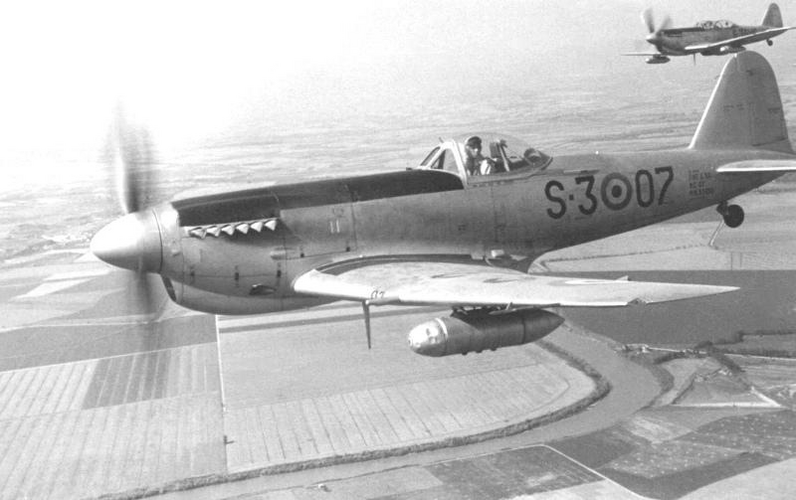
A WW2 fighter design for rugged areas

Hi,

So from this then I'd take Spitfire VIII as the starting point with Merlin 60 series. A fair margin on the speed and time to climb requirements.

With the in-service date specified as January 1943, I'm not quite sure a Merlin with +18 lbs/sqin will be available to us. Based on the performance of the Spitfire IX running a Merlin 61 at +15 lbs/sqin, we might not have a margin for the low-altitude requirement at all.

At this point I'd also thicken up the wing a bit and move to inwards retracting main undercarriage. Slightly lighter structure, slightly reduced max Mach (in a very steep high altitude dive)

Going to an inwards retracting main undercarriage in my opinion will actually increase weight, especially for an aircraft intended to be landed harder than the Spitfire.

Maybe need increased wing area - reduces max speed but there's loads of margin.

I'd agree that a big-wing Spitfire would seem like a possible starting point, but with the requirement to withstand substantially higher loads than the historical Spitfire, a bigger and stronger wing will be substantially heavier than the historic Spitfire wing.

Who knows on take-off and landing performance; it's complicated. There's probably enough performance margin elsewhere to add some big Fowler/Young man flaps for a mass/drag penalty if needed.

A big-wing Spitfire probably is good in terms of take-off performance, but all the extra weight is acting against it. Big flaps usually have the disadvantage of creating more of an unbalancing moment when extended, so the flapped big-wing Spitfire would probably need a longer and larger tail as well, which in turn requires the fuselage to be strengthened, further increasing weight. Additionally, this would make it more difficult to achieve an acceptable balance between evevator controllability and safety against inadverntant overloading in dives (which was a bit of a problem in the historic Spitfire already).

Otherwise, 4 x cannons in the outer wings.

I would really leave it at 2, especially with the heavy 250 rounds per gun load prescribed. I don't think we can afford to add non-essential weight.

A counter-rotating prop to minimise gyroscopic effects.

Heavy and complex, probably not good for maintenability.

Regards,

Henning (HoHun)
 
I don't disagree with most of that, it's all about what compromises you want to make. I can't say that a "Spitfire" with lower wing loading and heavier structure is something I'd go for.

Without data and real modelling tools it's difficult to work out what the real impact of changes will be. Like I said, those strength changes might easily add a few hundred lb to the empty weight >10% - turn rate and take-off are probably most sensitive to this.

From having more of a think through other near neighbours then I wonder whether a Fiat G.59 might be a better starting point? Otherwise I was considering Hawker Tornado/ Tempest III but with a Merlin instead - lighter weight for only slightly less power.
 
Err, the P-39 meets the VNE spec (P-39 VNE is 523 mph) . Typhoon too. The level speed requirements are not stringent neither.
Okay, your rugged area aircraft design starts off with that P39.

Drop the 37mm for a pair of 20mm in the nose.

The tricycle gear allows you to add big flaps for the takeoff and early climb requirements, add automatic LE slats outboard for aileron effectiveness. Split radiators and oil coolers into the wings. Add dive brakes.

Now clean everything up aerodynamically to regain your speed numbers.
 
Hi,

Without data and real modelling tools it's difficult to work out what the real impact of changes will be. Like I said, those strength changes might easily add a few hundred lb to the empty weight >10% - turn rate and take-off are probably most sensitive to this.

Here's a heuristic formulae for the weight of an aluminium wing, based on an analysis of a considerable number of real-world general aviation designs (so we might be operating a bit outside its primary range of application, but I don't think it will be far off):

View: https://youtu.be/G6aAcGDZTOc?t=252


Roughly, wing weight increases to the square root of wing area, and to the fourth root of cube of the ultimate load factor ... W ~ (S/S0)^0.75 * (Nz/Nz0)^0.5. That is for the wing being scaled up proportionally, and the design weight staying the same in spite of the wing's weight gain. The latter is a bit unrealistic, but in reality, you'd probably scale up the wing differently anyhow.

So if you incrase a wing by 20% while increasing the ultimate load factor from 10.5 to 13.5, the wing gets heavier by 30 %. Plus some extra weight gain for the increased design weight, plus some weight gain if you want to increase the aspect ratio, which will be beneficial for most interesting performance parameters (but detrimental for the roll rate).

From having more of a think through other near neighbours then I wonder whether a Fiat G.59 might be a better starting point? Otherwise I was considering Hawker Tornado/ Tempest III but with a Merlin instead - lighter weight for only slightly less power.

I haven't looked at the engine options beside the Merlin, but the 600 km/h @ 6km requirement might exclude the V-1710. The take-off condition requires brisk acceleration, which probably favours a radial engine as it tends to deliver higher power at lower speeds where the additional drag of the big engine and its air-cooling are not as telling. Basically, with more power for take-off, we can afford a smaller wing, which will help weight (further increasing take-off performance) and remediate the hit we take on top speed a little. It'll also help with robustness and maintainability (or at least concentrate the maintenance issues firewall-forward ;-)

Regards,

Henning (HoHun)
 
Okay, your rugged area aircraft design starts off with that P39.

Drop the 37mm for a pair of 20mm in the nose.

The tricycle gear allows you to add big flaps for the takeoff and early climb requirements, add automatic LE slats outboard for aileron effectiveness. Split radiators and oil coolers into the wings. Add dive brakes.

Now clean everything up aerodynamically to regain your speed numbers.
I actually like the idea.
The P-39 was the most streamlined US fighter after the Mustang (it was even winning the post-war air races), from late 1942 on it was managing above 600 km/h (385 mph was the official high speed figure for the -39N), it can house two, if not 3 20mm cannons in the nose (the P-39C have had a 37mm cannon, two HMGs and 2 LMGs in the nose), carried a bit more fuel than the Spitfire or Bf 109.
P-39 was less draggy than a Spitfire.

With the in-service date specified as January 1943, I'm not quite sure a Merlin with +18 lbs/sqin will be available to us. Based on the performance of the Spitfire IX running a Merlin 61 at +15 lbs/sqin, we might not have a margin for the low-altitude requirement at all.

British were testing the Mustang X with Merlin 65 on board in the second half of 1942, these were good for +18 psi.

I haven't looked at the engine options beside the Merlin, but the 600 km/h @ 6km requirement might exclude the V-1710.

V-1710, as used on P-40N, or on P-39N/Q, or on the P-51A, should propel the perspective fighter beyond 600 km/h, as it did with the fighters listed.
 
Hi Tomo,

V-1710, as used on P-40N, or on P-39N/Q, or on the P-51A, should propel the perspective fighter beyond 600 km/h, as it did with the fighters listed.

The requirement is 600 km/h at 6 km, which is harder to achieve than 600 km/h at an existing engine's best altitude.

According to this inclosure to a December 1942 report, the P-51 just barely made it: http://www.wwiiaircraftperformance.org/mustang/p-51-tactical-inc2.pdf

No data on the sea level speed is provided, but extrapolating from the 10000 ft and 5000 ft data points, it probably missed the 520 km/h @ sea level requirement (though not by much).

At 6 km, an engine with a single-speed, single-stage supercharger is going to be hard-pressed to deliver the kind of power needed for 600 km/h while also meeting the 520 km/h sea level requirement.

Regards,

Henning (HoHun)
 
The requirement is 600 km/h at 6 km, which is harder to achieve than 600 km/h at an existing engine's best altitude.

According to this inclosure to a December 1942 report, the P-51 just barely made it: http://www.wwiiaircraftperformance.org/mustang/p-51-tactical-inc2.pdf

Please note that I haven't say much about the P-51, but about the P-51A (difference in nomencalture is subtle, difference in ability is not).
Eg. see here - more than beats the required 600 km/h at 6 km, as well as 520 km/h down low, even without the use of WER.

At 6 km, an engine with a single-speed, single-stage supercharger is going to be hard-pressed to deliver the kind of power needed for 600 km/h while also meeting the 520 km/h sea level requirement.
To move away from the P-51A, please see here the P-39N: graph.
 
Hi Tomo,

Please note that I haven't say much about the P-51, but about the P-51A (difference in nomencalture is subtle, difference in ability is not).

That's post our 1 January 1943 target date, that's why I picked the earlier P-51[blank].

To move away from the P-51A, please see here the P-39N: graph.

True, it makes our required speeds, but only just. There's also a later test of a P-39Q-5 which doesn't make it (and of another that exceeds it), so I feel my use of the term "hard-pressed" was probably justified :)

However, my comment about excluding the V-1710 was not aimed at existing types, but rather at a fighter designed to fulfill Pasoleati's requirements, which are more demanding than the requirements the P-51 and P-39 were designed for. I'd still maintain that the V-1710 is not a good choice if one is going to try and meet the demanding requirements issued in this thread.

The single-speed, single-stage Merlin can probably be excluded as well, but as there are the Merlin 20 and the Merlin 60 series engines with better high-altitude capabilities, the Merlin as a general type still might be viable. I actually wonder if the Merlin 20 series might not be a better choice than the 60 series as it avoids the extra weight and complexity of the intercooler, as with the take-off and turn rate requirements being what they are, weight will be our main problem in my opinion. The intercooler also adds substantial drag both on the P-51D and the Spitfire IX/VIII.

I still think the Hercules might be the best choice overall, though.

Regards,

Henning (HoHun)
 
The P-39 can meet both speed requirements and the climb requirement. It meets even the TO requirement as as tested, it required approx. 300 m to reach 15 m and didn't even use WER.

As for the landing requirement, even the P-47 meets the 600 m req.

And Henning, drop that utter lie about stall.
 
Let me put it this way HoHun: Do you claim or do you not claim that a monoplane MUST automatically flick out of turn when stalling under g to prove it has "sufficient elevator authority"? MUST never fall straight through, MUST always flick out. Yes or no. One word.
 
Hi Pasoleati,

Let me put it this way HoHun: Do you claim or do you not claim that a monoplane MUST automatically flick out of turn when stalling under g to prove it has "sufficient elevator authority"? MUST never fall straight through, MUST always flick out. Yes or no. One word.

Actually, it's you who should clarify your requirements: MUST a flick from an accereated stall be impossible at all times for your fighter to be accepted? If your answer is "yes", congratulations, you're the proud operator of a canard aircraft now.

Regards,

Henning (HoHun)
 
That's post our 1 January 1943 target date, that's why I picked the earlier P-51[blank].
Engine that powered the P-51A (V-1710-81) was the same engine that powered the P-40M, 1st delivered in Novbember 1942.

True, it makes our required speeds, but only just. There's also a later test of a P-39Q-5 which doesn't make it (and of another that exceeds it), so I feel my use of the term "hard-pressed" was probably justified :)

It is probably not.
The P-39Q with HMG gondolas was draggier than the -N, so it is just to be expected that the test results might not be as good.

The single-speed, single-stage Merlin can probably be excluded as well, but as there are the Merlin 20 and the Merlin 60 series engines with better high-altitude capabilities, the Merlin as a general type still might be viable. I actually wonder if the Merlin 20 series might not be a better choice than the 60 series as it avoids the extra weight and complexity of the intercooler, as with the take-off and turn rate requirements being what they are, weight will be our main problem in my opinion. The intercooler also adds substantial drag both on the P-51D and the Spitfire IX/VIII.

A P-51 powered with Merlin 45 in winter of 1942/43 would've been even a tad faster than the P-51A, ditto if it was outfitted with Merlin 20 series. A cleaned-up and well-made Spitfire V would've met the specification, too.
How much of the added drag due to the intercooler was the P-51D suffering?

I still think the Hercules might be the best choice overall, though.

Not with it's drag, and lack of exhaust thrust before the 100 series.
 
Hi Tomo,

Engine that powered the P-51A (V-1710-81) was the same engine that powered the P-40M, 1st delivered in Novbember 1942.

Hm, we could plausibly use that for the sake of Pasoleati's exercise then.

The P-39Q with HMG gondolas was draggier than the -N, so it is just to be expected that the test results might not be as good.

Whatever fighter we might choose as a basis, it would be draggier than the original to fulfill Pasoleati's additional requirements, that's why I expect the end results from the V-1710 to be not as good.

I also have in mind that Pasoleati specified the use of 87 octane fuel (or water injection, which wasn't available for any of the specified engines in 1943 as far as I know), so the engines might not yield their full historical power in our fighter. Sorry, I meant to mention this earlier, but was distracted by some other detail of this discussion.

Not with it's drag, and lack of exhaust thrust before the 100 series.

My hope would be that the Hercules VI or maybe XVI would have enough power to overcome that disadvantage, but upon checking, I found that I don't reallly have any good Hercules data.

Regards,

Henning (HoHun)
 
The Petlyakov Pe-2's wing layout was an analog to a mid-wing or maybe even shoulder-wing fighter, not a low-wing fighter. I'm not sure it had fowler flaps either - these move rearward and downward, and are closer to the ground than split flaps or chamber-changing flaps.
Peter C Smith's Crowood book says the Pe-2 had Schrenk flaps. No rearward movement as in Fowler flaps.
 
I also have in mind that Pasoleati specified the use of 87 octane fuel (or water injection, which wasn't available for any of the specified engines in 1943 as far as I know), so the engines might not yield their full historical power in our fighter. Sorry, I meant to mention this earlier, but was distracted by some other detail of this discussion.

If the fuel is no better than 87 octane, Western engines (bar the R-2800 with lower boost?) will not cut the mustard.
 
Hi Tomo,

If the fuel is no better than 87 octane, Western engines (bar the R-2800 with lower boost?) will not cut the mustard.

Thinking about it, maybe your earlier idea from another thread, a lightened Fw 190 with a DB 605 engine, would actually be a pretty good contender here! :)

Regards,

Henning (HoHun)
 
Hi again,

Thinking about it, maybe your earlier idea from another thread, a lightened Fw 190 with a DB 605 engine, would actually be a pretty good contender here! :)

Hm, it looks like it misses the sea-level speed requirement:


It also totally fails with regard to the turn rate requirement, which might be the most difficult to achieve if the speed requirements are met.

Regards,

Henning (HoHun)
 
Hi again,


Hm, it looks like it misses the sea-level speed requirement:


It also totally fails with regard to the turn rate requirement, which might be the most difficult to achieve if the speed requirements are met.

Regards,

Henning (HoHun)

Reduce the weight of guns & ammo (also removes some drag => adds speed), as per OP, and install the Fowler flaps?
 
Hi Tomo,

Thinking about it, maybe your earlier idea from another thread, a lightened Fw 190 with a DB 605 engine, would actually be a pretty good contender here! :)
Regards,

Henning (HoHun)

Another suggestion - the Fw 190 powered by a Jumo 211N. At SL (without ram), the max power at Notleistung was ~1460 HP, or some 100 HP more than what the restricted (2600 rpm, 1.30 ata) DB 605 was making. The 100 extra HP might just allow us to get to the 520 km/h mark, hopefully.
Altitude power (again without ram) - 1280 HP at 4.9 km, or about 100 HP less at 5.7 km, where the restricted 605A makes 1250 HP.
Incorporating the swirl throttle on the engines would've improved the low-alt power (no need to wait until late 1943 for that); applicable also for other V12s, of course.
For the extra light weapon suite - two MG FFMs outboard of the prop disc (preferably belt-fed, and a bit sped-up) + two MG 131s in the wing roots.
 
If the fuel is no better than 87 octane, Western engines (bar the R-2800 with lower boost?) will not cut the mustard.
That was sort of in my mind too; maybe need some AH variant that uses water injection as specified to get to similar boost levels as 100oct without (ish)

From going through the specified engines then I'm pretty sure Merlin offers the best power to mass / size and so this gives us more margin in the design. I don't see how R-2600, Hercules or Kinsei would meet the speed requirement at all; e.g. J2M is slower and is pretty clean and high(ish) wing loading. Maybe add a rocket as well

Maybe an AH Merlin 20 series with WI (to get near 18lb boost from 87 Oct fuel?) And revised gearing for slightly different performance across the altitude performance points? For a bit less mass and size than the 60 series.

Then it's into looking at historical airframes and what blend of characteristics we need; e.g. P-51 is low drag but heavy so very marginal on say the time to climb requirement. Hence starting with something similar to the smaller lighter weight Spitfire airframe and changing some of the aerodynamic features to lower drag towards P-51 levels e.g. propulsion installation

But G.55/59 or Macchi 205 also seem like valid bases. Say like the below with LE radiators instead of the chin and ventral, probably a bit lower aspect ratio wing to emphasise roll rate, a nice big fin fillet...

1704835680765.png
 
That was sort of in my mind too; maybe need some AH variant that uses water injection as specified to get to similar boost levels as 100oct without (ish)

From going through the specified engines then I'm pretty sure Merlin offers the best power to mass / size and so this gives us more margin in the design. I don't see how R-2600, Hercules or Kinsei would meet the speed requirement at all; e.g. J2M is slower and is pretty clean and high(ish) wing loading.
Japanese (Mitsubishi, actually) were probably the 1st to introduce WI on their in-service engines, like the Kasei 20 series on the G4Ms and Kinseis on the Ki-46s. Such a Kasei installed on something low-drag will offer a lot of power at low and medium altitudes, while still being a light and reasonably small engine.
 
87 octane? Are you f*ing kidding me?

No. Hell No.

Yes, I know that the US is basically the only place to get 100 octane. Or 115 octane, late in the war.

I don't see any British or American engines meeting your performance demands on 87 octane, not without serious methanol/water injection. Adding 200+ lbs of methanol/water to the plane is going to hurt all performance numbers.
 
Such a Kasei installed on something low-drag will offer a lot of power at low and medium altitudes, while still being a light and reasonably small engine.
My comparison point is the J2M; its a fairly neat installation on that aircraft but a better job could probably be done e.g. forced cooling, aligned exhaust stubs etc. But I don't think there's much other scope for reducing drag as its already a pretty compact airframe and the wing loading is relatively high. So then when I look at the max speed of J2M then I think we're pretty marginal on speed @ altitude, even with a better engine installation. If we relax this speed requirement then it might become an option.

Yes, I know that the US is basically the only place to get 100 octane. Or 115 octane, late in the war.
Or the UK, from early war in small amounts and then inceasing
 
My comparison point is the J2M; its a fairly neat installation on that aircraft but a better job could probably be done e.g. forced cooling, aligned exhaust stubs etc. But I don't think there's much other scope for reducing drag as its already a pretty compact airframe and the wing loading is relatively high. So then when I look at the max speed of J2M then I think we're pretty marginal on speed @ altitude, even with a better engine installation. If we relax this speed requirement then it might become an option.
Whoops, my bad, that should've read 'Kinsei', not 'Kasei'.
 
Hi,

My comparison point is the J2M; its a fairly neat installation on that aircraft but a better job could probably be done e.g. forced cooling, aligned exhaust stubs etc.

I just read "The Zero Fighter" by Okumiya/Horikoshi/Caidin, which also covers other Mitsubishi types, including the J2M. To my suprise, it states that the shape of the J2M's fuselage was owed to compressiblity concerns, but it turned out that the Japanese estimates of the effect of compressibility on transonic drag rise had been exaggerated.

The J2M might look neat, but it's a very voluminous aircraft, which according to "The Zero Fighter" was the reason it was chosen for trialling a turbo-supercharger installation, as it had the "most spacious fuselage of all Navy fighters".

The Kasei, by the way, was subject to serious vibration problems for pretty much all of 1943, which weren't fully resolved ever, and required the use of thick propeller blades that were aerodynamically unfavourable. That was one of the reasons for the J2M's disappointing top speed.

So for the purpose of this thread, I would consider the Kasei out of the running, even if its nominal power values appear to be very good and the engine was actually suited for the use with low-octane fuel with water injection. ("The Zero Fighter" considers water injection a bit of a disappointment, though.)

Regards,

Henning (HoHun)
 
The Kasei, by the way, was subject to serious vibration problems for pretty much all of 1943, which weren't fully resolved ever, and required the use of thick propeller blades that were aerodynamically unfavourable.
Would that be 'all Kaseis were the subject of vibration problems', or just the Kaseis as used on the J2M?

("The Zero Fighter" considers water injection a bit of a disappointment, though.)
Is the reasoning behind disappointment stated?
 
Hi Tomo,

Would that be 'all Kaseis were the subject of vibration problems', or just the Kaseis as used on the J2M?

It's not stated perfectly clearly, but as the proper (never implemented solution) either would have been to re-design the engine to work with a different arrangement of the master rods of the two rows of the radial engine along with the addition of a mass-balance driven at twice the engine speed, I think it concerns all Kasei engines.

In fact, the book points out that the Homare had similar problems, and also saw the use of thickened propeller blades as a work-around. It seems a prototype Homare 21 with the above fix was produced, which ran for 400 hours on the test stand before being tested in a C6N1 Myrt, where it was able to use the original thin-bladed propeller to gain 16 mph in top speed while running with much reduced levels of vibration.

Is the reasoning behind disappointment stated?

Not very clearly, in my opinion. The drawbacks were:

- Reduced full throttle height (no surprise)
- Drop in power during the hot summer seasons
- Frequent malfunction caused by changes in atmospheric conditions
- "At best, the water-methanol injection was a poor substitute for high-octane fuel, and the normal operation of the aeroplane suffered."

It's worth noting that the water-methanol injection seems to have never worked for the Navy's A6M, while the Army's Ki-43 when using basically the same engine appears to have used it operationally in large scale. That's a bit of a paradox in my opinion.

Regards,

Henning (HoHun)
 
It's not stated perfectly clearly, but as the proper (never implemented solution) either would have been to re-design the engine to work with a different arrangement of the master rods of the two rows of the radial engine along with the addition of a mass-balance driven at twice the engine speed, I think it concerns all Kasei engines.

Is that re-design from your point of view, or something that was specified in the book? Further - was the Kasei on the G4M also suffering of the vibration problems?

Not very clearly, in my opinion. The drawbacks were:

- Reduced full throttle height (no surprise)
- Drop in power during the hot summer seasons
- Frequent malfunction caused by changes in atmospheric conditions
- "At best, the water-methanol injection was a poor substitute for high-octane fuel, and the normal operation of the aeroplane suffered."
Points 1 and 2 cannot be 'blamed' to the WI, but I'm sure you already know that.
Pont 3 might use a bit more research?
Point 4 had nothing to do with Mitsubishi - it was not their fault that Japan had no regular access to the high-octane fuel, thus burdening the engine companies to find solutions of how to increase the engine power on the engines in series production.

It's worth noting that the water-methanol injection seems to have never worked for the Navy's A6M, while the Army's Ki-43 when using basically the same engine appears to have used it operationally in large scale. That's a bit of a paradox in my opinion.
Possibly it never worked due not to be installed in the 1st place?
I'd really want to know more of the Ki-43s using the water-alcohol injection in regular service.
 
Hi Tomo,

Is that re-design from your point of view, or something that was specified in the book? Further - was the Kasei on the G4M also suffering of the vibration problems?

The re-design is specified in the book, the "not very clear" part is whether it really applies to "all" Kaseis.

Regards,

Henning (HoHun)
 
Hi Tomo,


That's post our 1 January 1943 target date, that's why I picked the earlier P-51[blank].


True, it makes our required speeds, but only just. There's also a later test of a P-39Q-5 which doesn't make it (and of another that exceeds it), so I feel my use of the term "hard-pressed" was probably justified :)

However, my comment about excluding the V-1710 was not aimed at existing types, but rather at a fighter designed to fulfill Pasoleati's requirements, which are more demanding than the requirements the P-51 and P-39 were designed for. I'd still maintain that the V-1710 is not a good choice if one is going to try and meet the demanding requirements issued in this thread.

The single-speed, single-stage Merlin can probably be excluded as well, but as there are the Merlin 20 and the Merlin 60 series engines with better high-altitude capabilities, the Merlin as a general type still might be viable. I actually wonder if the Merlin 20 series might not be a better choice than the 60 series as it avoids the extra weight and complexity of the intercooler, as with the take-off and turn rate requirements being what they are, weight will be our main problem in my opinion. The intercooler also adds substantial drag both on the P-51D and the Spitfire IX/VIII.

I still think the Hercules might be the best choice overall, though.

Regards,

Henning (HoHun)
Henning - FWIIW, the A-36 then P51A, then (even moreso) B/D reduced cooling drag for both climb and cruise when compared to Mustang I and IA (P-51-NA).

The essential features whch were changed included:
1. Eliminating the alligator jaw variable intake scoop.
2. Improved fixed intake geometry, with progressively better boundary layer control (lower lip and the 'gutter')
3. Improved geometry of the inner plenum to provide better velocity gradient from intake to combined intercooler/radiator matrix face. The pressure distribution across the matrix face was much better in the B/C than even the A which was better than the A-36, etc., etc. The H was the ultimate design for the Mustang series by achieving all the benefits from earlier models plus improving heat retention and jet effect by extending the aft plenum and adding better shutter control via better thermostat control system.

I tend to consider the 1650-1 as a better 'fit' so long as high altitude performance is not introduced into the discussion. The Allison V-1710-81 in the P51A with or without WI, however seems to be viable. Additionally, the P-51-NA with an easy replacement of 1710-81 for the-39 also should be considered - but swap out the Oldsmobile Hispano for the Brit version. I would swap those for 2xMG151/20.

Th P-51A had same T.O. Power at 57" as the 1650-3 at 61" and due to lighter airframe outperforms P-51B except in roll at altitudes under 13-15K. I suspect that the P-51 while slightly heavier, wuld perform extremely well with the -81 even without WI.

Your thinking as usual is very crisp. Enjoy reading your posts - ditto TomoP
 
Care to provide a source wrt. who was that guy, and when he suggested that, to whom?
F-IR-6-RE
Survey of Messerschmitt Factory and Functions
Oberammergau, Germany

subsection; An Investigation of the Messerchmitt Plant at Oberammergau, Germany with Particular Reference to Aircraft Armament Equipment
schwartz armor mess.png
I'll note that some Lippisch designs had a thick steel skin instead of the normal armor arrangement. Perhaps Schwarz influenced Lippisch, or maybe the other way around.... or maybe someone else influence both... or they independently realized the same thing.

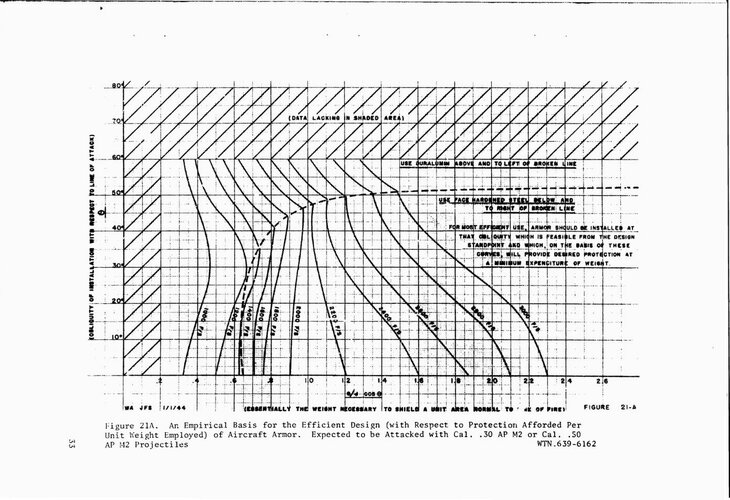
Here is a chart from a WW2 era US report on armor
aircraft armor grapho.jpg
For defeating American projectiles thick Al skin is the way to go.
Hi Sienar,


If the plane stalls at 8 degrees flaps down, the aircraft would be designed to give a corresponding ground angle to allow a safe landing. However, the full stall wouldn't really occur at the angle at which the flapped wing section stalls, as usually the outboard wing section with the ailerons doesn't have Fowler flaps. (The early He 177 had ailerons that doubled as high-lift flaps, but that was rather unusual and was changed to a more conventional setup on later versions.) You can probably even provide a non-uniform stall angle over the flapped section by shaping the flaps accordingly - now that I think it, that might be the reason for the tapering shape of the Japanese "butterfly" flaps.

In spite of this, there's still an issue for safe landings, and that's when the flaps don't extend, for example due to battle damage, as with a reduced ground angle, you can't stall the aircraft on landing without striking the ground tailwheel-first.

So with regard to the objective of creating a rugged aircraft operating from rough landing grounds, Fowler flaps do indeed have some drawbacks in addition to their mechanical complexity.


For some reason, my impression is that braking wasn't considered terribly important when operating from rough fields in WW2. I'm not sure at the moment what the reason was - I'd speculate that both the effect of braking on the individual wheels while bouncing over a rough surface was difficult (so as not to lock them inadventently when they're momentarily unloaded), and that skidding one wheel while braking the other might lead to a dangerous loss of directional control.

It's worth noting that Messerschmitt developed and tested a fast-acting variable speed propeller that also provided reverse thrust for braking on landing. Thinking about modern turboprop-powered STOL aircraft for operation from rough fields (like the Pilatus Porter), they also use this technique, so maybe wheel brakes aren't really the solution we're looking for. I don't know enough about this topic to state this with any kind of authority, though.

Regards,

Henning (HoHun)
General guidelines are 10-12 degrees for taildraggers, if it is lower than that stability on the ground suffers. I don't think there are many taildraggers at just 8 degrees.

With regards to braking, I'm under the impression that brakes were generally poor in WW2 and in particular brake life was bad as well as poor tire life. Perhaps this is why pilots would skimp on the braking, that is trying to extend brake and tire life?


Although I was getting at something a bit different with the braking point - what is the goal of putting fowlers onto a fighter? Is it just to lower the pattern/final speed by a bit?

Normally one of the reasons for wanting to lower the landing speed is to try and shorten the landing roll as well. There is a very strong link between ground roll and touchdown speed. But if fowlers are on a taildragger then the brakes can't be slammed as fast so the landing speed is lower but there is not much of a distance benefit. In this case you'll be getting something like half the benefit of fowlers.

Re reversing props, I believe the US and British experimented with them as well. The charts I've seen/have show very powerful braking so that probably is the way to go if braking is a big requirement.
Hi,


Here's a heuristic formulae for the weight of an aluminium wing, based on an analysis of a considerable number of real-world general aviation designs (so we might be operating a bit outside its primary range of application, but I don't think it will be far off):

View: https://youtu.be/G6aAcGDZTOc?t=252


Roughly, wing weight increases to the square root of wing area, and to the fourth root of cube of the ultimate load factor ... W ~ (S/S0)^0.75 * (Nz/Nz0)^0.5. That is for the wing being scaled up proportionally, and the design weight staying the same in spite of the wing's weight gain. The latter is a bit unrealistic, but in reality, you'd probably scale up the wing differently anyhow.

So if you incrase a wing by 20% while increasing the ultimate load factor from 10.5 to 13.5, the wing gets heavier by 30 %. Plus some extra weight gain for the increased design weight, plus some weight gain if you want to increase the aspect ratio, which will be beneficial for most interesting performance parameters (but detrimental for the roll rate).
There is a bit of a problem with using a formula like that for WW2 era fighters.

Skin thickness will be determined by max dynamic pressure. That will occur at VNE which tends to be very high for WW2 fighters.

The method I've been using for estimating wing weights for WW2ish aircraft is like this;
1. Figure out the skin area of the wing (very easy with a computer)
2. Use an appropriate skin thickness based on comparable aircraft (0.04-0.05 inches is typical)
3. Assume the ribs+rivets will be ~50% the skin weight (this is based on historical data)
4. Calculate the spar weight using a spreadsheet (this is a bunch of math)

I've done this for some ww2 fighters I have wing weights for and it ends up being in the ballpark, around +/-10%.
 
F-IR-6-RE
Survey of Messerschmitt Factory and Functions
Oberammergau, Germany

subsection; An Investigation of the Messerchmitt Plant at Oberammergau, Germany with Particular Reference to Aircraft Armament Equipment
I'll note that some Lippisch designs had a thick steel skin instead of the normal armor arrangement. Perhaps Schwarz influenced Lippisch, or maybe the other way around.... or maybe someone else influence both... or they independently realized the same thing.

Here is a chart from a WW2 era US report on armor
For defeating American projectiles thick Al skin is the way to go.

Thank you for the feedback :)
 
Hi Bill,

Henning - FWIIW, the A-36 then P51A, then (even moreso) B/D reduced cooling drag for both climb and cruise when compared to Mustang I and IA (P-51-NA).

Thanks a lot for chiming in, you're definitely the Mustang expert here! I thought I had seen the drag increase in the coefficients I caculated in the analysis attempts I made long ago, but when I went back and checked my numbers, they weren't as I remembered ... might well have been my flawed memory.

I tend to consider the 1650-1 as a better 'fit' so long as high altitude performance is not introduced into the discussion.

Agreed - in my preference for the Merlin 20 series, the V-1650-1 was silently included even if that might not have been technically correct.

Your thinking as usual is very crisp. Enjoy reading your posts - ditto TomoP

Thanks a lot! I'm enjoying your book too, though I haven't progressed beyond the 1943 summary yet. Lots of interesting details I haven't read anywhere else before!

Regards,

Henning (HoHun)
 
Hi Sienar,

General guidelines are 10-12 degrees for taildraggers, if it is lower than that stability on the ground suffers. I don't think there are many taildraggers at just 8 degrees.

Primarily because of the reduced nose-over margin, I guess?

Although I was getting at something a bit different with the braking point - what is the goal of putting fowlers onto a fighter? Is it just to lower the pattern/final speed by a bit?

My personal preference would be not putting them on our fighter at all, but Pasoleati suggested their use with a view primarly on their use as manoeuvre flaps. STOL is in our requirements, too.

But if fowlers are on a taildragger then the brakes can't be slammed as fast so the landing speed is lower but there is not much of a distance benefit.

Is this again because of the nose-over tendency? With regard to a tail-dragger with high-lift devices, the Westland Lysander comes to my mind. In the light of your comments, I suspect they were using a fairly far aft centre-of-gravity position, but it was an aircraft in which it was vitally important always to use the correct elevator trim, and to avoid opening the throttle suddenly when in landing configuration.

The method I've been using for estimating wing weights for WW2ish aircraft is like this;
1. Figure out the skin area of the wing (very easy with a computer)
2. Use an appropriate skin thickness based on comparable aircraft (0.04-0.05 inches is typical)
3. Assume the ribs+rivets will be ~50% the skin weight (this is based on historical data)
4. Calculate the spar weight using a spreadsheet (this is a bunch of math)

Sounds good, but for the purpose of estimating the effect of a change in ultimate load factor and wing area, what scaling laws can we derive from this? Points 2 and 3 will only scale (approximately linearly) with wing area, so it's point 4 that will have to answer to the load factor change.

Regards,

Henning (HoHun)
 
…. Going to an inwards retracting main undercarriage in my opinion will actually increase weight, especially for an aircraft intended to be landed harder than the Spitfire. ….
Spitfire’s outward-retracting landing gear was better than Me.109 …. but it did not work well during hard landings on aircraft carriers.
Note how the last Spitfire variants: Spiteful and Seafang got inward-retracting gear.
So for junior pilots landing on rough fields, wide landing gear is more foregiving.
 
Dear Scott Henny,
Another way to tame snap-rolls is installing the NASA-developed, drooped and extended outboard leading edges as installed on Cirrus and Quest Kodiak. With a larger leading edge radius - in front of the ailerons - outboard panels stall well after wing roots and help maintain aileron control into the stall. In that respect they function similar to the after-market STOL kits developed by Robertson, Sportsman, Wren, etc.
NASA leading edges can be identified by the step in the leading edge.

If you allow late 20th century aerodynamics on your fictional fighter, then you as well go full “Schumann Wing” as seen on leading competition sailplanes, Formula One and Sport Class racers. Schumann wings are characterized by gently swept, elliptically-tapered leading edges and trailing edges that are straight or - ideally - have a slight elliptical sweep. The goal is to minimize the size of wing tip vortices by minimizing pressure differentials between the top and bottom skins.
 
Last edited:
If you allow late 20th century aerodynamics on your fictional fighter, then you as well go full “Schumann Wing” as seen on leading competition sailplanes, Formula One and Sport Class racers. Schumann wings are characterized by gently swept, elliptically-tapered leading edges and trailing edges that are straight or - ideally - have a slight elliptical sweep. The goal is to minimize the size of wing tip vortices by minimizing pressure differentials between the top and bottom skins.
So, instead of the Spitfire's elliptical wing, you have the same leading edge and a straight trailing edge?

The idea seems like it could have been invented in the 1940s. And I can see it being done trying to simplify production, not for aerodynamics.
 
Hi Rob,

Spitfire’s outward-retracting landing gear was better than Me.109 …. but it did not work well during hard landings on aircraft carriers.
Note how the last Spitfire variants: Spiteful and Seafang got inward-retracting gear.
So for junior pilots landing on rough fields, wide landing gear is more foregiving.

I wouldn't disagree with the conclusion, but the Me 109's landing gear issues in reality were quite minor, and if you dig for statistics of take-off/landing accidents, or the relation of enemy-inflicted vs. total losses, there is actually no difference to the Fw 190 with its supposedly far superior landing gear. There was a stretch in 1940 in which landing gear damage was a strain on the maintenance and repair organisation, but that concerned the Me 109E that didn't have a tailwheel lock, which was subsequently introduced.

I hasten to add that the bad reputation of the Me 109 is not a post-war thing ... I've actually found German WW2 files that heavily criticize how the separation of flight training schools in basic and advanced training leads to the flight instructors in the basic schools, who did not get to fly the Me 109 and did not train their students on the type, fed stories of how quickly the Me 109 would crash if mishandled to their pupils. These stories lead to a heavy bias of these pupils against the Me 109, and occasional ill-advised panic reactions instead of the smooth and steady inputs one needed to operate a Me 109 safely.

Compare this to the American style of building pilot confidence along with competence, immortalized by variations of, "If you can handle the T-6, flying the P-51 will be a breeze".

Regards,

Henning (HoHun)
 
Hi Bill,


Thanks a lot for chiming in, you're definitely the Mustang expert here! I thought I had seen the drag increase in the coefficients I caculated in the analysis attempts I made long ago, but when I went back and checked my numbers, they weren't as I remembered ... might well have been my flawed memory.
Calculating (or isolating) delta cooling drag increments (IMO) based on flight tests are impossible with one exception that I can point you to -but that was a P-51B-1.

Earlier wind tunnel testing from X73 through NA-99 utilized a variety of methods to simulate the drag of bringing freestream air in the plenum to stagnation (plates, baffles, etc) but nothing could model the Meredith effect to offset the pressure delta throughthe cooling matrix.

So, absent NAA Performance Analysis reports we were driving to interpolating drag between low speed results and high speed results to look at effect of closed vs open exit shutter.

Otherwise Hoerner examples pretty much had to serve and exhaust gas thrust was a guess absent such methods as the NACA presented (but not well known and I personally never saw them in udergraduate or graduate school. You and others on ths forum are well versed but I suspect that 'back in the day' when we were ponticating on various drag relationships 20 years ago, we were handicapped - at least I was.

But even with Hoerner, compressibility factors were absent and at the end of the day, reducing CDtotal to airframe component profile drag at least matching wind tunnel proportions was beyond our grasp.
Thanks a lot! I'm enjoying your book too, though I haven't progressed beyond the 1943 summary yet. Lots of interesting details I haven't read anywhere else before!

Regards,

Henning (HoHun)
Henning - thanks for the kind words. A word of caution. The Osprey art team mangled several of my excel spreadsheets, notably the table citing P-509 through NA-91 dimensions, the Allison engined Mustang Victory Credits, the Drag comparisons between the NACA full scale drag testing/report vs the B, the D and the H.

I have regrets on the typos, but in some defense Osprey was trully frantic to get the book to press as Covid reared its ugly head, so typos that I caught and mis-statements on images remained. For some reason my editor saw fit to alter my identifications to correct 'obvious mistakes'. Naming the A-36 "Apache" was one. The other was citing 41-038 with 4x20mm cannon arriving at NACA Langley from Eglin Field testing as 'unknown Mustang' are but two examples.

Last but not least, our book in .pdf format was pirated by a russian website and made available to all for at least a year before Osprey Legal shut them down. That said there is no way that they could prevent a resurection on a different site.

In my new book I will dedicate a chapter to corrections. The book will pick up the Mustang story in the middle of 1943 and walk everybody through the 'bubble top' and lightweight fighter genesis.


Right now I am in research to try to nail the slight changes made from XP-51F to G airframe dimensions so that I can construct a table of changes from P-509 all the way through P-51H.


Regards,

Bill
 
Hi Bill,

Calculating (or isolating) delta cooling drag increments (IMO) based on flight tests are impossible with one exception that I can point you to -but that was a P-51B-1.

You might be right, but all I was looking at was gross drag, with no real way to attribute it to any particular aspect of the airframe. The cooling system as a major change between airframes would be the "usual suspect", but as I haven't even looked at the issue systematically, I'm not actually in a position to even hypothesize.

Would you expect the V-1650-1 or some other Merlin-20-series engine to perform better up to 6 km than a Merlin 61, provided the only difference in the airframe we install it in is the intercooler?

The Spitfire Vc with Merlin 45 seems to be a faster aircraft than the Spitfire IX at low altitudes at equivalent power levels, that's what got me thinking ... a Merlin 20 should extend that superiority a bit toward higher altitudes, and the weight savings from omitting an intercooler would certainly help us to meet Pasoleati's other performance requirements (aside from speed).

Henning - thanks for the kind words. A word of caution. The Osprey art team mangled several of my excel spreadsheets, notably the table citing P-509 through NA-91 dimensions, the Allison engined Mustang Victory Credits, the Drag comparisons between the NACA full scale drag testing/report vs the B, the D and the H.

Ah, thanks for the warning! Sounds like just the thing that could have thrown me into serious confusion! :) I'm certainly looking forward to your next book, not only for the corrections. I hope Osprey improved their information security, that's unfortunately becoming ever more important these days.

Regards,

Henning (HoHun)
 

Similar threads

Please donate to support the forum.

Back
Top Bottom