Cjc

ACCESS: Secret
Joined
15 October 2021
Messages
375
Reaction score
325
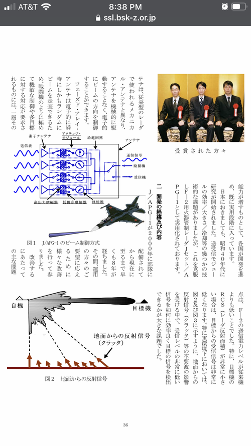
The one thing am curious about this radar is, could it have been made small enough to fit in a regular f-16 or was the increased size of the f-2 nessary inorder to fit it.
And how much would that have effected its range because as is, iv seen the J/APG 1's range as described as in between the apg-66 and the apg-68 which frankly could mean its range only dealt with its increased size and not that it was asea.
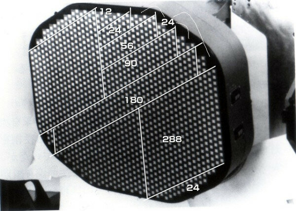
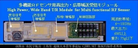
You beat me to making this topic lol. I have a FOIA for test data on the Enginnering model flight test data given by Japan to the DoD as part of the technology transfer agreement. The paper you talking about I am actually quite familiar with. The Author is actually referring the document I want. The reason he says that J/APG-1 is in between APG-66 and APG-68 is because the Engineering model is considerably less powerful then the final J/APG-1. He mentions the T/R modules between the EM and FM (flight model, final production hardware) are virtually equivalent (3w) but what he didn’t know, or rather couldn’t have know is the FM has over 1200 T/R modules vs 808 for the EM. Almost all publications including several GAO reports cite the 808 number However looking at the unit
1662917365919.jpeg
You can see 1216 units which is a dramatic difference in power.

There are quite a few antidotes to show the J/APG-1 outranges early 2000s incarnations of APG-68(v)5


110km look up 65km look down. I have a few mentions of the early F-2 doing well against Misawa block 50 aircraft. That would only really be possible if this was true because in the early 2000s the F-2 only had AIM-7F and USAF F-16 had AIM-120c5.

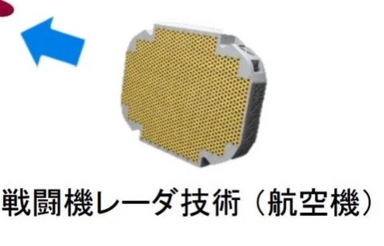
As to putting J/APG-1 in an F-16, it’s 150KG so a bit lighter then APG-68 but antenna size is 70cm (j/apg-2 is listed as 72cm) this is closer in size to apg-65. The real issue is cooling though only the block 60 has the needed cooling system and APG-80 is in between j/apg-1 and j/apg-2 in power so it’s not really needed.
 
Well APG-66/68 family antenna is 75 x 48 cm in size. Since F-2 is based on F-16, particularly Agile Falcon program back then the J/APG-1 antenna size must not be far off.

As to putting J/APG-1 in an F-16, it’s 150KG so a bit lighter then APG-68 but antenna size is 70cm (j/apg-2 is listed as 72cm) this is closer in size to apg-65.

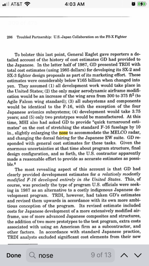
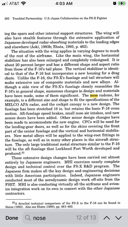
Not really, you see, F-18 family have circular nose cross section while F-2 is eliptical. Thus APG-65 is bigger than APG-66/68 and thus the J/APG-1.
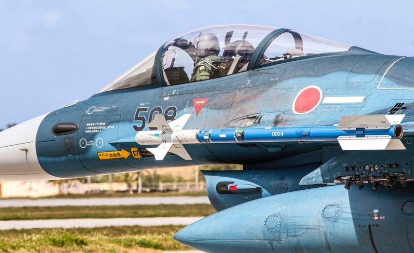
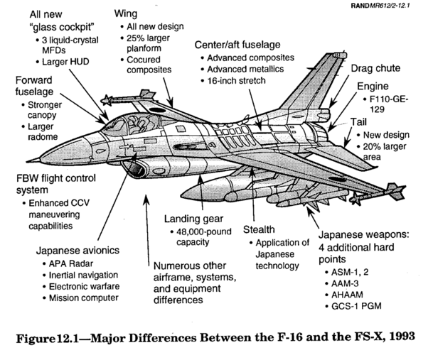
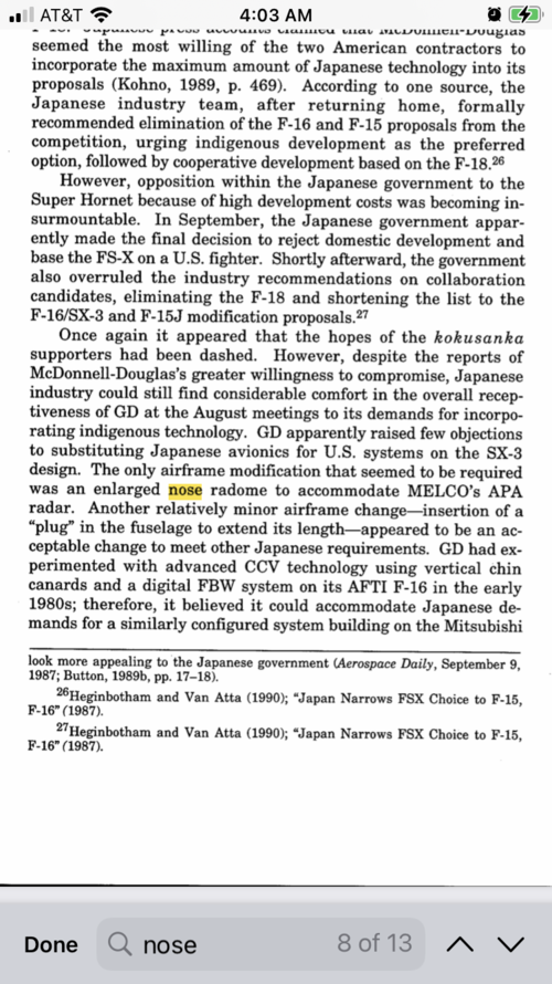
The F-2 has a nose that is longer and wider then the F-16s. If you look closely it droops down compared to the F-16. B0B58CA8-D67C-4EBD-9991-5E71D33AF93D.jpeg 53C6A9B8-8528-40DA-A987-46CFB5985226.png 15F52200-C7F8-40A0-9736-2E3A7B0419C5.png 42DB14B5-A77C-4F6C-832A-A3A71CB00F82.png 75780169-2726-4D38-90F6-D90F106F3A4E.png
 
Last edited:
Future fire control system, the precursor to J/apg-1. Started in 1981 and came as a surprise to several US technical teams. First flow on a modified C-1 in 1986; early on the Japanese teams had some difficulty getting the T/R modules to work together. Problem seems to have been solved by April 1987. Used very large (Six inch long!) T/R modules and nicknamed the “Dragonfly’s eye” to to AESA being superficially similar to a compound eye. Software was later used in J/APG-1.
 

Attachments

  • 8211864C-508F-40BD-BA3A-ACA1AEA4F4C1.png
    8211864C-508F-40BD-BA3A-ACA1AEA4F4C1.png
    273.1 KB · Views: 76
I guess tangentially related since this thread is about the J/APG-1, but do we have any info on the J/APG-2 improvements. Early on I saw that it was simply integration of the AAM-4 capability for the F-2, but that doesn't make much sense to increment the number simply for that since the F-15J integrated the AAM-4 on it's existing radar with no designation change.

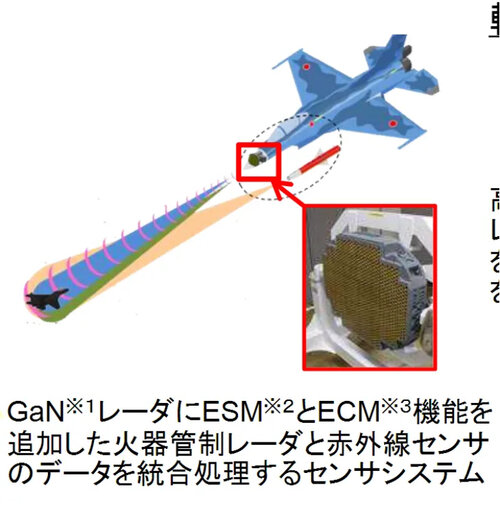
I think it was the website where this photo is from made the claim that the J/APG-2 changed to GaN from the J/APG-1 GaAs

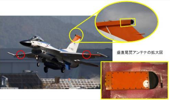
I also saw something a while back that an F-2 flew as a testbed for an F-X radar development. I think it was this one. Any info would be appreciated.
1663212827170.jpeg
 
I guess tangentially related since this thread is about the J/APG-1, but do we have any info on the J/APG-2 improvements. Early on I saw that it was simply integration of the AAM-4 capability for the F-2, but that doesn't make much sense to increment the number simply for that since the F-15J integrated the AAM-4 on it's existing radar with no designation change.

I think it was the website where this photo is from made the claim that the J/APG-2 changed to GaN from the J/APG-1 GaAs

I also saw something a while back that an F-2 flew as a testbed for an F-X radar development. I think it was this one. Any info would be appreciated.
View attachment 684110
Hi friend!

J/APG-1 was built with the support fighter role in mind the idea of upgrading for air superiority missions is old dating back to Mitsubishi’s bid to replace the F-4


When the Fs-x program was underway Aesa radars where expensive. The dem Val radars in the ATF program cost as much as a new F-16. The investment from the ATF program ended up making other systems more affordable. Japan got around this by designing its modules very conservatively. In the late 2000s when Japan’s security situation had changed the F-2 was upgraded to have enhanced air to air capability. AAM-4 requires a separate command transmitter. J/apg-1 was large and there was no place to put it. J/apg-1 predates XAAM-4 and for whatever reason JASDF never seemed to have any interest adding AMRAAM to the F-2 (JMSIP F-15j and the F-35 both can carry AMRAAM).


This key topic sites an Avation week article on the subject no Jwiki has a lot of interesting info


Basically new radar modules and undisclosed modifications to antenna (rumor was 6w GaN citing a 2001 TRDI paper I can’t find)

New signal processor

New search algorithms and software

Said to be APG-79 class

New Radome

Unknown if cooling has been upgraded

It’s made by modifying the existing radar but I’m not actually sure how similar the two are in terms of modes search algorithms ect. I don’t believe any pictures exist of it


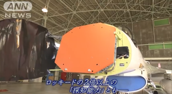
As for the new radar yes it was tested on the F-2 at Gifu I attached one image but I have a very detailed article. The XF-2 with the light grey nose are carrying it. It’s described as a J/apg-2 derivative. I saw some tweets implying it might be added to line F-2.


Attachments

  • D3CD462F-E958-43E7-84EE-93ADF1452081.png
    D3CD462F-E958-43E7-84EE-93ADF1452081.png
    741 KB · Views: 99
  • 360C2B94-7011-4F0B-9C5E-5893A783A093.png
    360C2B94-7011-4F0B-9C5E-5893A783A093.png
    281.9 KB · Views: 119
BTW what's the story about early production -1 having software problems leading to beamforming failure and thus limiting range much?
I heard their where some software integration issues but the actual problem was the Radome changed from the early test program and it wasn’t accounted for (Pitot tube placement seems to be the most commonly cited issue) it apparently was never a problem for air to ground and resolved fairly quickly (2002? With the F-2 on air defense patrol definitely by 2004) for air to air with some unspecified countermeasures. J/APG-2 apparently uses a different Radome.

Stealth I’m still looking for the answer to your question, I might not have it till I get some documentation related to the design which may be up to six months.
Ah, so it wasn't software but radome. Interesting. Do you have any details?
Not really unfortunately, I just heard it mentioned a lot and it was considered for J/APG-2.


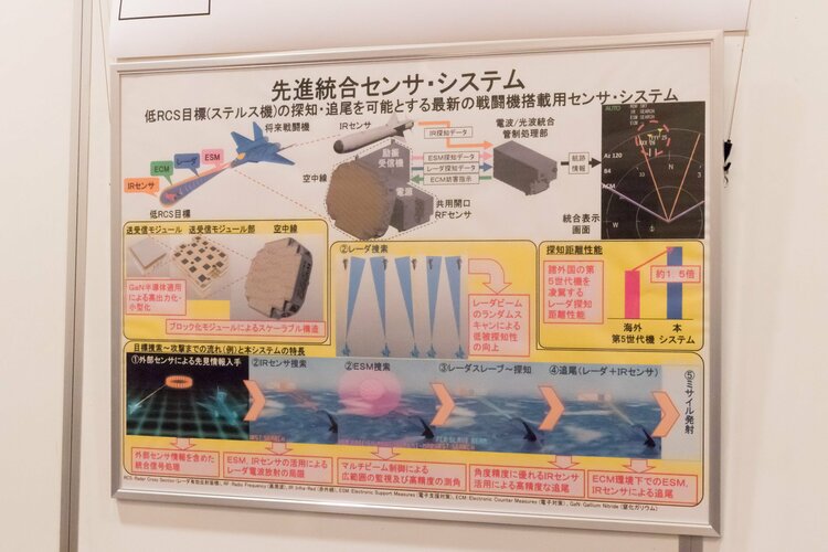
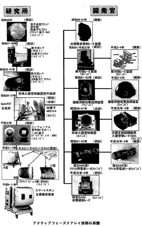
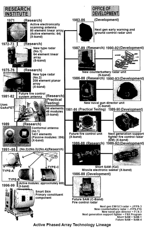
Japanese AESA research with a genealogy of Japanese Phased array technology.
 

Attachments

  • 763FE518-6CD9-4EC9-88DB-A9A89BD12267.png
    763FE518-6CD9-4EC9-88DB-A9A89BD12267.png
    260.1 KB · Views: 129
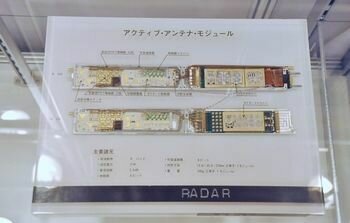
One thing I’m curious about is the Future fire control system’s T/R modules. They are fairly long at about Six inches compared to the 3.5 for the j/apg-1 and 2.5 for the ATF dem Val. Are they True MMIC or Hybrid MIC like THE CONTEMPORARY SSPA. The sources I’ve seen are ambiguous.
 

Attachments

  • 07C19A3C-74DB-4E71-8590-A6A736C210E4.jpeg
    07C19A3C-74DB-4E71-8590-A6A736C210E4.jpeg
    20.2 KB · Views: 103
  • 36634CF7-6EB0-49BE-8ABA-BA9615FF1CDB.png
    36634CF7-6EB0-49BE-8ABA-BA9615FF1CDB.png
    120.9 KB · Views: 105
I wanna thank my buddy Nemo KB for the translation
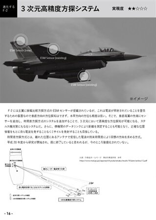
Do you have any idea if the conformal antennas were mounted on any test airframe? From the looks of it, it was planned for the original concept of FS-X, but that wasn't built. Was there an XF-2 that maybe tested them?
 
I wanna thank my buddy Nemo KB for the translation
Do you have any idea if the conformal antennas were mounted on any test airframe? From the looks of it, it was planned for the original concept of FS-X, but that wasn't built. Was there an XF-2 that maybe tested them?
Yes fairly recently too, it’s at the bottom of one of the links up top “3d search system”
 

Attachments

  • 1D95DF50-6E55-47E1-B6DD-D2E43D15A2D8.png
    1D95DF50-6E55-47E1-B6DD-D2E43D15A2D8.png
    232.5 KB · Views: 100
  • 25301FD2-E292-481B-8880-6BB2B47E44A1.jpeg
    25301FD2-E292-481B-8880-6BB2B47E44A1.jpeg
    45.3 KB · Views: 84
Last edited:
any information about the range of J/APG-2
Japanese mod claim APG-79 class

Military periscope claims a 300 precent power increase over J/apg-1 along with a new signal processor for a 120km range without stating what rcs.

That one blogger above had access to an mod pdf with some information on GAN T/R modules under development at the same time seems to agree with the APG-79 comparison but I don’t have access to the PDF he’s talking about so I can’t see for myself. (I’d like to run it through Stealthflankers calculator)
 
I want to thank @MissileMan and the National electronics museum for this.

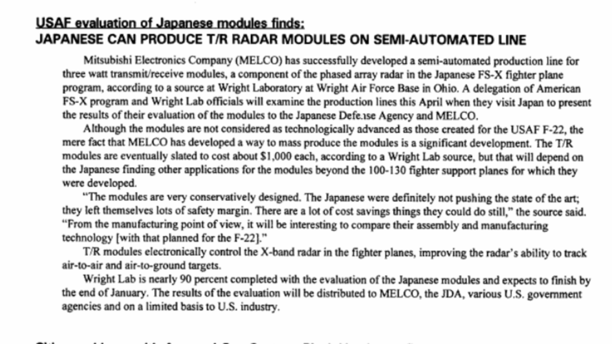
This is an evaluation of the J/APG-1 T/R modules by Wright Laboratory in 1994. These five modules are actually Japan’s first post war export.
 

Attachments

  • FS-X_Active_Phased_Array_Radar_Eval_Report.pdf
    4.3 MB · Views: 49
I want to thank @MissileMan and the National electronics museum for this.

This is an evaluation of the J/APG-1 T/R modules by Wright Laboratory in 1994. These five modules are actually Japan’s first post war export.
Wow! Thank for the sharing this insane find information. Not so many expect America to buy Japanese radar technology.
 
I want to thank @MissileMan and the National electronics museum for this.

This is an evaluation of the J/APG-1 T/R modules by Wright Laboratory in 1994. These five modules are actually Japan’s first post war export.
Based off of other papers, such as ADA283773, that these T/R modules were not for the J/APG-1. These are from the prototype "dragonfly" aesa prototype that came before the J/APG-1. As we can tell by the fact it array is composed of 800 T/R modules instead of the 1216 of the J/APGs. This prototype was known to have very poor power (as stated by this report, only 3.5 watts per T/R module), for a total of only 2.8kw on the 800 module array, or 4.3kw on a 1216 array. It's extremely likely the T/R modules were significantly redesigned between this and the J/APG-1, as this power output is far too low to be effective for a long range AESA radar, even accounting for the fact the J/APG-1 is known to be on the lower end of the scale.
 
Based off of other papers, such as ADA283773, that these T/R modules were not for the J/APG-1. These are from the prototype "dragonfly" aesa prototype that came before the J/APG-1. As we can tell by the fact it array is composed of 800 T/R modules instead of the 1216 of the J/APGs. This prototype was known to have very poor power (as stated by this report, only 3.5 watts per T/R module), for a total of only 2.8kw on the 800 module array, or 4.3kw on a 1216 array. It's extremely likely the T/R modules were significantly redesigned between this and the J/APG-1, as this power output is far too low to be effective for a long range AESA radar, even accounting for the fact the J/APG-1 is known to be on the lower end of the scale.
It’s mentioned in the 1995 and 1997 GAO reports that these are for the F-2,

Active Phased Array Radar System


To evaluate the F-2’s active phased array radar system, the U.S. Air Force


acquired five transmit/receive modules to test and evaluate at its Wright


Laboratory. The radar was of interest to DOD because it incorporates new


technologies; however, some officials believe that U.S. radar technology


being developed for the F-22 is a generation ahead of Japanese technology.


Although there is limited commercial application for a fire control radar,


some of its parts could be of interest to U.S. companies and at least one


U.S. company expressed interest. In general, the U.S. industry participants


were favorably impressed with the level of access to active phased array


radar technology during the visit but found that the technology was not

quite as advanced as expected. Also, industry participants observed that


the approaches used by Japanese industry to package and seal the radar


modules are not a low-cost approach by U.S. industry standards.

The United States has obtained more information on the Japanese active


phased array fire control radar than any other non-derived FS-X


technology. In August 1992, DOD purchased five Japanese FS-X radar


transmit/receive modules, supporting connectors, and technical data for


testing purposes. DOD paid the then current Japan Defense


Agency/Mitsubishi Electric Corporation prototype module contract price


of $4,800 per unit and about $70,000 for technical data and additional


items required to test the modules.


Mitsubishi Electric officials reported in November 1993 that they had


reduced module unit costs to about $3,300. Mitsubishi Electric officials


would like to reduce module costs even further by increasing the module


production run to at least 20,000 units annually. Mitsubishi Electric’s cost


goal is about $1,400 per unit for the FS-X program, assuming production of


120,000 units (or enough for about 130 aircraft). Mitsubishi Electric


officials noted that they do not expect to reach the $1,400 per module goal


until 2 years into full-rate FS-X production.


Mitsubishi Electric officials said they will pursue commercial applications


for FS-X transmit/receive modules that could reduce module costs during


FS-X production. Mitsubishi Electric officials noted, however, that


commercial applications are not practical at this time because of the


modules’ high cost. Commercial applications could include air traffic


control antennas, satellite and mobile communications, and anticollision


automobile radars.


In August 1993, U.S. engineers at the Wright Laboratory Solid State


Electronics Directorate began testing the five radar modules DOD


purchased from Japan. By February 1994, the United States had finished a


complete set of verification tests for module performance. The tests


indicated that the modules perform according to specifications and will


meet Japanese FS-X radar requirements. A U.S. engineer involved in the


testing said that the performance of Japanese modules was very good and


in one area are on a par with the best U.S. modules.


In May 1994, a U.S. radar module testing team visited Japan to compare


and verify U.S. and Japanese test results. U.S. engineers may conduct


additional tests to assess the performance of FS-X radar modules relative


to U.S. modules planned for use on the F-22 aircraft.1 DOD was preparing a

The Rand report mentions these are from the Flight model which is the production standard J/APG-1 (the engineering model is from 1989)

At the time of this writing, no radar technology has yet been transferred to U.S.


industry. The USAF, after a one-year negotiation with Japan, had received five


sample T/R modules from a MELCO production run of the FS-X flight model


(FM) radar in October 1993. The Air Force Aeronautical Center's Wright


Laboratory has completed evaluating and testing the sample modules. Although


the Air Force has no specific application in mind, it will distribute test results to


other US. government agencies and to US. industry. These results are intended


to allow U.S. recipients to determine whether to pursue a licensing agreement


with MELCO regarding its module technology.17

It goes on to talk about comparing the earlier engineering models flight test results

In addition, along some measures, the FS-X EM radar can be considered lower than the U.S. state-of-art. In particular, flight test results of the EM supplied by the JDA indicate considerably lower detection range, sidelobe suppression, and resolution than the U.S. F-16/APG-68 one of the most advanced U.S. systems compatible with F-16 or FS-X-sized aircraft.? In addition, the operating ranges of the FS-X EM radar are several times worse than the APG-68 in track-while scan and range-while-scan modes. FS-X imaging resolution specs were also several times worse than the APG-68 and APG-70. Because DoD is aiming for a system of far higher performance than existing radar systems with the F-22 radar, it is safe to say that the performance specs of the FS-X EM are far lower than those of the F-22 radar.®

I’ve attempted to contact the author to see where to get this Flight test data but to date have been unsuccessful

EM used provisional hand made T/R modules which had equal power but worse characteristics in noise, bandwidth, reviver gain.

The gist of the report is that the Fs-X modules were a compromise solution for affordability

Nevertheless, some aspects of the FS-X system indicate a clear decision by Japan


to develop a system somewhat below the maximum capability obtainable. For


example, Japanese engineers had apparently decided to keep the FS-X T/R


modules simple by not designing any variable gain into them, although they


clearly have the capability to do so. Without variable gain, the FS-X array would


not be able to utilize amplitude modulation to achieve even better beam control


than PPARs. However, many of the technical difficulties caused by variable gain


errors in T/R modules could be avoided.


The use of array thinning to amplitude taper19 the FS-X antenna reflects another


example of Japan's pragmatic decision to compromise potential performance for


the sake of reducing costs. Some of the elements away from the array center are


fitted with lower power and nonactive modules to taper the array2 ° so that

variable gain would not be necessary. While this approach saved considerable


engineering effort and costs, it also represented a performance compromise from


an array utilizing variable gain modules.


Japan's cost emphasis can be further revealed by the kinds of improvements


made in their FM21 T/R modules over the EM modules. Most improvements


were in producibility and cost rather than performance. The most notable


change is the substantial increase in MMIC integration, resulting in a new


module prototype that contained only half the number of parts and chips as the


EML22 The MMIC fabrication processes were also significantly upgraded for


improved manufacturability. Improvements in quality control also enabled a


new module that did not require timing adjustments after assembly.23


Despite the dramatic improvements in producibility, the FM performance hardly


changed from the EM Despite an entirely new active circuitry, module size and


transmit power of the FM were identical to the EM. The internal circuitry was


not revamped to shrink the module and increase its power. Instead, it was done


to improve on module cost and producibility.

To achieve superior beam control, the F-22 T/R modules also may contain


functions of variable gain,26 which the FS-X modules lac&L 27 Requirements on


mapping resolutions also appear to drive wider module bandwidths than the


FS-X. MELCO engineers have noted their capability to develop modules of


higher peak power and wider bandwidths2 8 but have apparently found such


improvements unnecessary to meet FS-X requirements.29

[28During the FS-X Radar Symposium, MELCO had revealed some active-circuit GaAs MMIC


technology of comparable performance to those developed in the United States.]

Should the United States be interested, given current Japanese technical


capabilities in APAR? The numerous APAR flight tests already conducted in


Japan indicate a more than rudimentary technical capability in military systems


integration. Although the FS-X performance is lower than the U.S. F-22 and the


APG-68, the EM prototype has been judged to be better than the F-16/APG-66,49


a defense system with strong export sales. The DoD team charged with


evaluating the FS-X radar had judged Japan to be only "three years behind in


realizing APAR of improved RF performance." With Japan nearing completion


of the FM radar, a system that should be considerably improved over the EM,5 0


the FS-X radar could be the first break for Japan in advanced military radar


systems.51

[50 The FM module specidfcation shows solid improvements over the EM in noise figure, receive


gain, and bandwidth. Consequently, the FM should be a more capable system than the EM. which


has already been judged to be more advanced than the F-16/APG-66. Ibid.


511n receive performance, the FM is competitive with US. module prototypes developed as


recently as 1990. The FS-X Radar Technology Symposium and Manuturing Ternoogyfor Radw


Transmit Raive Modules, op. cit.]

the dragon fly also known as the future fire control system used large six inch modules


These modules are not MMIC but hybrid modules which are larger and more


Anyway overwhelming air to air detection was not a major concern for the J/APG-1 reliability and production where. It wasn’t till J/APG-2 (which I believe was originally developed for an interceptor variant of the F-2 to replace the F-4) That The F-2 would get a radar with excellent BVR capabilities (comparable to APG-79).
 
I want to thank @MissileMan and the National electronics museum for this.

This is an evaluation of the J/APG-1 T/R modules by Wright Laboratory in 1994. These five modules are actually Japan’s first post war export.
Wow, what a find. How long was it since you've been digging for this document? I recall seeing your post about contacting DTIC to no avail. I was also very curious about the results of the evaluation results of this thing mentioned in the RAND book, so here's my big thanks for sharing this, also to @MissileMan .
 
Wow, what a find. How long was it since you've been digging for this document? I recall seeing your post about contacting DTIC to no avail. I was also very curious about the results of the evaluation results of this thing mentioned in the RAND book, so here's my big thanks for sharing this, also to @MissileMan .
A while!

I started a few years before I posted this. I still have to find the JDA flight test data. I’m looking into a trip to the National archive to try my luck. If I could get that and the Melco video I would be a happy man
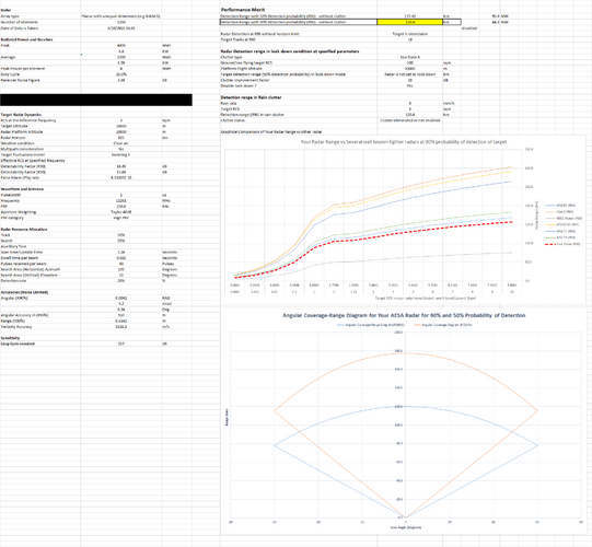
Some prediction. Based on that document. Looks decent tho 120 Km with PD of 90%, and capability to track 18 targets at that range.
I saw an estimate of “over 60nm” once so I think that is dead on. Their is apparently a Japanese magazine in the 2000s where someone mentions off hand it has 35nm detection for a 5sq meter target in down look.

Thank you so much for running that!
 
Some prediction. Based on that document. Looks decent tho 120 Km with PD of 90%, and capability to track 18 targets at that range.
Looks very promising! one thing though, as per the attached file, the beam control period is less then 4ms, so the stated dwell time is roughly an order of magnitude too high.
 

Attachments

  • 先進統合センサ・システム(その3)の研究試作(1).pdf
    1.8 MB · Views: 11
Looks very promising! one thing though, as per the attached file, the beam control period is less then 4ms, so the stated dwell time is roughly an order of magnitude too high.

What is the beam control period ? Is it the switching time for the phase shifter to the next beam or the dwell time ?

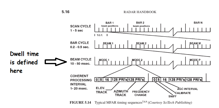
Dwell time here is defined as how long a radar "beam" will stay in an area within its frame (The time taken to scan entire area e.g 120 x 11 deg is referred as "Frame time" Which usually last 5-10 seconds or more) The other term for dwell time is "beam cycle" which last for 0.01 to 0.05 seconds or 10-50 miliseconds.

For me the beam control period is how long the phase shifter in the module "switch" to new beam position.
From how I took it in this case was the minimum time it takes it to look at an area. Including detecting things within it. The reason for this is it's time is, really really high for if it was just how long it takes it to look in a new direction. That should generally be measured in microseconds, so a time of [less then 4ms], is nearly an order of magnitude larger then would be expected, and there genuinely should be very little reason for this discrepancy. Phase shifters work by adjusting a magnetic field over a ferrous core to slow or accelerate the flow of electrons through it. so there is very little reason for a beam control period to exceed the microsecond range.

I honestly also agree that this isn't the best word for it, but i'm assuming it's an issue of translation? From what i've heard from technicians who work on military aesa stuff, 4ms is a lot more in line for the time to search an area then to change it's direction of search. Although I am aware that "someone said so" isn't exactly reliable either.
 
I honestly also agree that this isn't the best word for it, but i'm assuming it's an issue of translation? From what i've heard from technicians who work on military aesa stuff, 4ms is a lot more in line for the time to search an area then to change it's direction of search. Although I am aware that "someone said so" isn't exactly reliable either

Yeah looks like a translation issue.

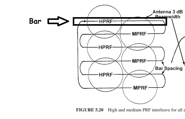
It's more into a CPI (Coherent Processing Interval). This is from 3rd edition of Radar Handbook. On subejct of Multifunctional fighter radar. Like A fighter radar may scan this way :

1743367181532.png

The bar is where the beam sweeps. Collection of bars is referred as Scan cycle or Frame time. In each bar there are Beam cycle which how long a radar beam may "stay" before moving. Which further defined below.

TOT-DwellTime.png

As you see the beam cycle is where the Dwell time or TOT (Time on Target) Lies. Which i used as reference for my AESA radar calculator for typical value of bar cycle. The CPI (Coherent Processing Interval) is where radar modes (e.g high-low and medium PRF) Are used. 4ms is clearly too small for beam cycle. Especially considering pulsewidth of typical fighter radar of 1 microseconds. 4ms is 4000 microseconds which if 1 microseconds pulse is used.. that correspond to PRF of just 4 KHz, low PRF which might not be a suitable candidate for say air to air modes.

Edit-adding coirrection to the 2nd image. It should be Beam cycle where the dwell time is defined.
 
Last edited:


Write your reply...
Back
Top Bottom