flateric

ACCESS: USAP
Staff member
Top Contributor
Senior Member
Joined
1 April 2006
Messages
11,156
Reaction score
8,966
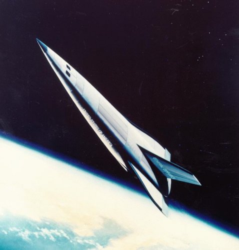
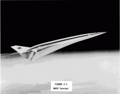
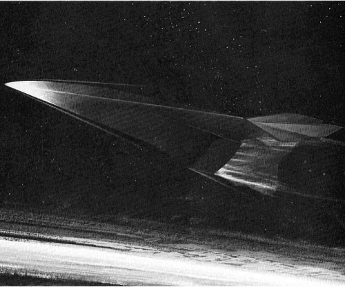
Thread to discuss configurations of National Aero-Space Plane (X-30) from various contractors.

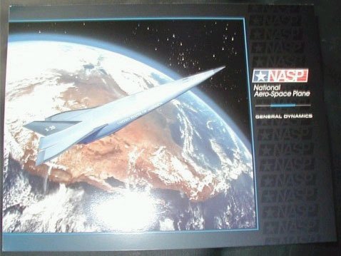
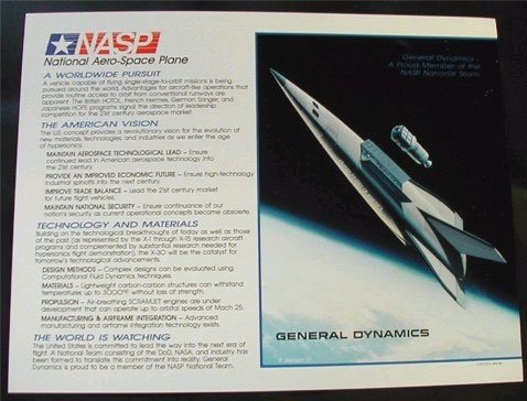
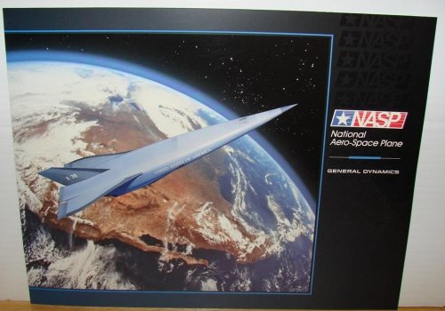
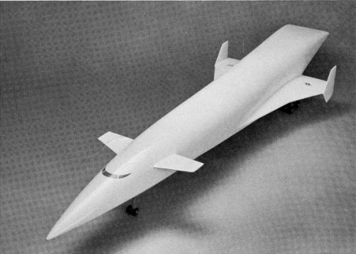
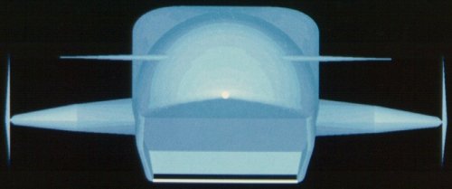
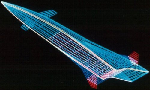
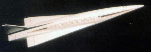
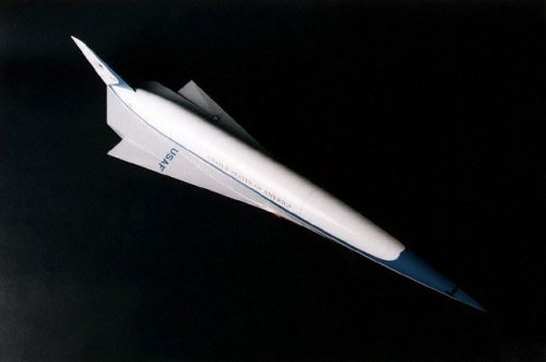
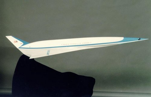
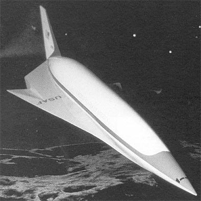
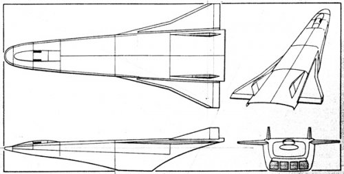
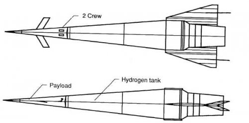
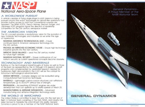
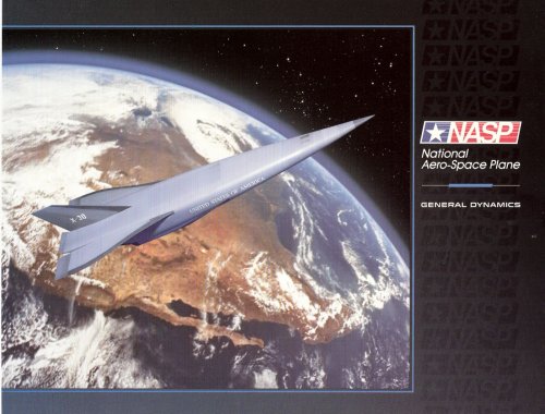
General Dynamics proporsal graphics.
 

Attachments

  • GD_NASP.jpg
    GD_NASP.jpg
    35.9 KB · Views: 1,118
  • gdnasp01.jpg
    gdnasp01.jpg
    38.7 KB · Views: 1,017
  • gdnasp02.jpg
    gdnasp02.jpg
    44.4 KB · Views: 1,062
  • x-30gd2.jpg
    x-30gd2.jpg
    154.3 KB · Views: 1,094
  • gdfwnasp.jpg
    gdfwnasp.jpg
    378.6 KB · Views: 955
Last edited:
Marquardt NASP promo (Marquardt wasn't a contender in NASP gameplay)
 

Attachments

  • Untitled-3.jpg
    Untitled-3.jpg
    82.1 KB · Views: 418
  • Untitled-2.jpg
    Untitled-2.jpg
    106.3 KB · Views: 426
  • Marquard_nasp03.jpg
    Marquard_nasp03.jpg
    53.5 KB · Views: 346
  • Marquard_nasp02.jpg
    Marquard_nasp02.jpg
    138.6 KB · Views: 322
  • Marquard_nasp01.jpg
    Marquard_nasp01.jpg
    95.4 KB · Views: 398
Rocketdyne NASP proporsal
 

Attachments

  • nasprcktd.jpg
    nasprcktd.jpg
    321.9 KB · Views: 484
  • NASP_Rocketdyne_800x609.jpg
    NASP_Rocketdyne_800x609.jpg
    43.2 KB · Views: 488
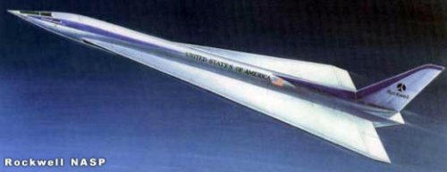
Rockwell International NASP
 

Attachments

  • rock_nasp89.jpg
    rock_nasp89.jpg
    52.6 KB · Views: 435
  • NASPR89D.jpg
    NASPR89D.jpg
    10.7 KB · Views: 450
  • image006.jpg
    image006.jpg
    15.1 KB · Views: 370
  • image003.jpg
    image003.jpg
    11.3 KB · Views: 355
  • image002.jpg
    image002.jpg
    8.7 KB · Views: 383
Nice. Anymore pictures of different companies proposals anyone? As far as I know NASP contractors included Boeing, Lockheed, McDonnell Douglas, General Dynamics and Rockwell, with Pratt & Whitney and General Electric for propulsion research, and Rocketdyne later contributing to NASP under its own funding. I wasn't aware of Marquardt also participating.
 
Boeing NASP proporsal
 

Attachments

  • x30boeing.jpg
    x30boeing.jpg
    75.5 KB · Views: 444
  • x-30-AC86-0699_a.jpg
    x-30-AC86-0699_a.jpg
    50.4 KB · Views: 383
  • naspea.jpg
    naspea.jpg
    52.5 KB · Views: 370
  • nasp07.jpg
    nasp07.jpg
    24.2 KB · Views: 366
  • NASP2BOE.jpg
    NASP2BOE.jpg
    11.9 KB · Views: 331
  • boeing.jpg
    boeing.jpg
    27.2 KB · Views: 368
  • 086.jpg
    086.jpg
    56.4 KB · Views: 371
  • 17.gif
    17.gif
    29.3 KB · Views: 362
McDonnell Douglas NASP proporsal
 

Attachments

  • nasp-mdc86.jpg
    nasp-mdc86.jpg
    103.5 KB · Views: 341
  • MDDX-30-2.jpg
    MDDX-30-2.jpg
    33.2 KB · Views: 344
  • mdcnasp01.jpg
    mdcnasp01.jpg
    90.6 KB · Views: 381
  • Clipboard20.jpg
    Clipboard20.jpg
    142.6 KB · Views: 395
flateric said:
Scott, don't you have any info on 'right' stuff?

I have annoyingly little hard data on NASP designs, and most of the good stuff I have isn't for public consumption. NASP remains *tightly* controlled and classified. Sadly, a lot of pre-NASP artwork got recycled by the various firms during the NASP days, and a lot of hypersonic transport ("Orient Express") artwork was called NASP. Most of the McD art you show is actually of an HST, not NASP... though the clearly orbital vehicles are shown to have the exact same geometry. NASP then as now was very classified, and non-NASP designs were cranked out for the public. The companies had to show *something.*

An interesting note: The McD designs you show are clearly in the lineage of the X-43 "Hyper-X." Compare the vertical stabilizers and small wings with those of the X-43... they're much the same. The main difference is with the nose; the X-43 has a wide "spatula" nose to capture more air for the engine. And even here, the X-43 is not a unique design; it is a greatly scaled-down version of a Mach 10 recon/strike vehicle derived from NASP work. This McDonnell-Douglas "Phantom Works" project dated from the extremely late 1980's to the late 90's, and might still be alive to some degree.

I was going to direct you to the drawings on my "bomber projects" page since I created 4-views of the Mach 10 cruiser some months ago; but it seems that I haven't updated that page in rather a long time.
 
Orionblamblam said:
I have annoyingly little hard data on NASP designs, and most of the good stuff I have isn't for public consumption. NASP remains *tightly* controlled and classified.
Oh, he could tell you, but then he'd have to kill you. :D
 
'As leader of the X-30 National Aerospace Plane team, he well remembers the day that designers decided to experiment with a spatula-shaped fuselage design-now used in most Boeing hypersonic concepts-that was better suited for horizontal flight.

"This was unlike any hypersonic configuration ever conceived," he said. The craft featured a nose like a spatula, sharp leading edges, a highly non-circular body cross-section, and tails like a fighter aircraft. Only a month had been spent on developing what was called the Non-Circular Body, Krieger noted.

"Those of us in the control room who were part of the National AeroSpace Plane team couldn't have been more proud when the X-43A made its first successful flight," he said. "As well as technical achievement, the X-43 symbolizes a determination to think way outside of the box, to leave behind a traditional concept and come up with a breakthrough design." '

*- Bob Krieger, president of Boeing Phantom Works

Boeing Frontiers Online
http://www.boeing.com/news/frontiers/archive/2004/july/ts_sf8a.html
 
flateric said:
"This was unlike any hypersonic configuration ever conceived," he said. The craft featured a nose like a spatula, sharp leading edges, a highly non-circular body cross-section, and tails like a fighter aircraft.


Errr.... the "unlike any hypersonic configuration ever conceived" is plain wrong. Spatular noses for hypersonic designs have been around since at least the early '60's, and the zealous followers of Vincent Burnelli would like to sue the bejeebers out of Boeing for "stealling" the Burnelli GB888 configuration.

http://www.mysteriesofcanada.com/Canada/Canada_Car/burnelli_designs.htm
 
So-called 'converged' design appeared on 10/29/90 AW&ST cover
 

Attachments

  • 3-v.jpg
    3-v.jpg
    51.2 KB · Views: 463
  • final_nasp_005.jpg
    final_nasp_005.jpg
    133.6 KB · Views: 371
  • final_nasp_004.jpg
    final_nasp_004.jpg
    32.6 KB · Views: 376
  • x-30-cutaway.jpg
    x-30-cutaway.jpg
    44.6 KB · Views: 418
  • nasp09[1].jpg
    nasp09[1].jpg
    58.8 KB · Views: 385
  • 33-NASP.jpg
    33-NASP.jpg
    53.4 KB · Views: 393
Several months later nose on public pictures became flattened from a blunt cone to a rounded edge wedge, but the rest of the design was consistent with the 10/29/90 AW&ST cover
 

Attachments

  • naspmock.jpg
    naspmock.jpg
    81.7 KB · Views: 477
  • IH017982.jpg
    IH017982.jpg
    58.8 KB · Views: 541
  • x30c.gif
    x30c.gif
    96.8 KB · Views: 467
  • x30b.gif
    x30b.gif
    69.1 KB · Views: 471
  • x30a.gif
    x30a.gif
    82.2 KB · Views: 470
  • X-30-roundwedgenose.jpg
    X-30-roundwedgenose.jpg
    29.2 KB · Views: 488
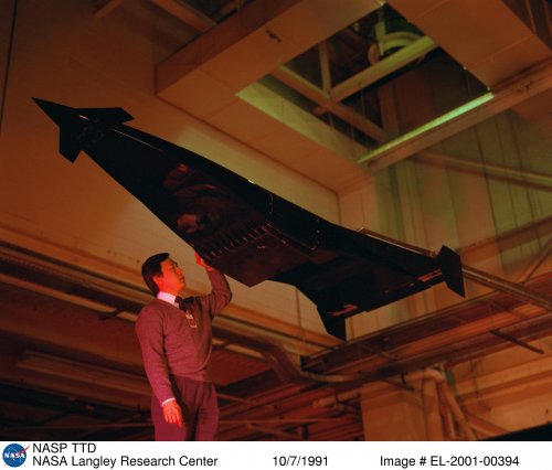
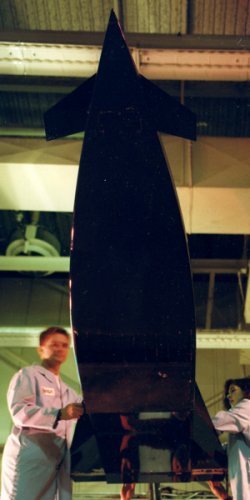
March 1991 NASA Langley photos of NASP Test Technique Demonstrator (TTD)
 

Attachments

  • 1991_NASP_TTD.jpg
    1991_NASP_TTD.jpg
    681.8 KB · Views: 264
  • p100.jpg
    p100.jpg
    56.7 KB · Views: 328
  • nasp-TTD.jpg
    nasp-TTD.jpg
    92.5 KB · Views: 350
  • ttd91-02.jpg
    ttd91-02.jpg
    48 KB · Views: 352
  • ttd91-01.jpg
    ttd91-01.jpg
    64.1 KB · Views: 312
Last edited:
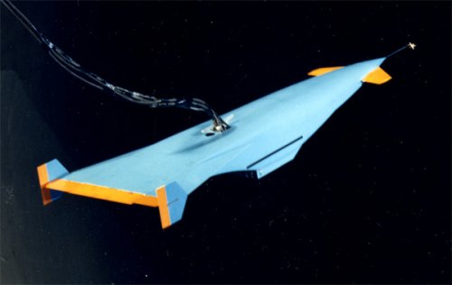
NASA Langley, TDT Tunnell, November 1992 - NASP model is mutating again (if that really NASP-related).
Interesting, that later ARSLS (Advanced Reusable Small Launch System) craft looks pretty close to wind tunnel model.
 

Attachments

  • weights.jpg
    weights.jpg
    24.5 KB · Views: 330
  • mos.jpg
    mos.jpg
    43.2 KB · Views: 371
  • ARSLS-3views.jpg
    ARSLS-3views.jpg
    29.5 KB · Views: 455
  • EL-1996-00226s.jpg
    EL-1996-00226s.jpg
    93.9 KB · Views: 436
Here two interesting drawings related with the program X-30 that (I believe) are not very well-known.

- An illustration of the possible escape system projected for the X-30, based on a ejectable booth that would reduce the speed until Mach 1.3- 0.7 and a special version semi-encapsulated of the ejection seats ACES 2 that would complete the escape sequence starting from that speed. Versions were also studied totally encapsulated to the style of those used in the B-58 or the XB-70 but I don't know any illustration of the same ones.

-The second drawing corresponds to the HALO (High Altitude Launching Option) proposed by Lockheed and dedicated to a preliminary exploration of the aerodynamic concepts implied in the X-30.
It was projected to be an airship of 17.7 meters that would be thrown by a SR-71 modified and it would reach speeds from Mach 10-12 to a altitude of 44200 meters.
 

Attachments

  • X30ejection.jpg
    X30ejection.jpg
    190.3 KB · Views: 898
  • HALO.jpg
    HALO.jpg
    265 KB · Views: 935
Dronte, thanks a lot, I've never seen both things.
Can you point on a sources?
 
It is this way. The images are of the copies of November '92 and April '93 of the Argentinean edition of PM.
 
This is probably close to 'final' converged X-30 configuration (aka "configuration a202") and 1993 Langley TTD Tunnel photo (intersesting that WT model seems to lack scramjet module somewhere - may be, it's just aeroelastic model) - note that double-delta wings mutated to all-movable rudders while rudders and vertical fins leading edges became swept back.

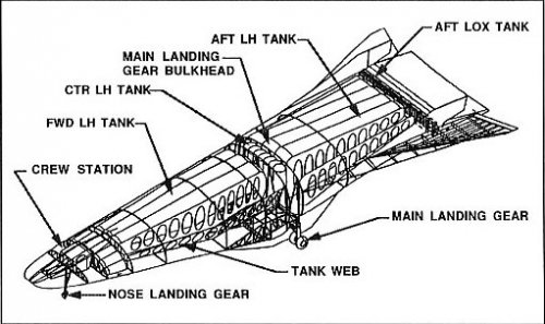
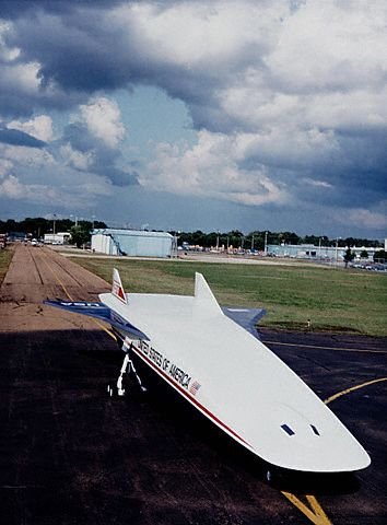
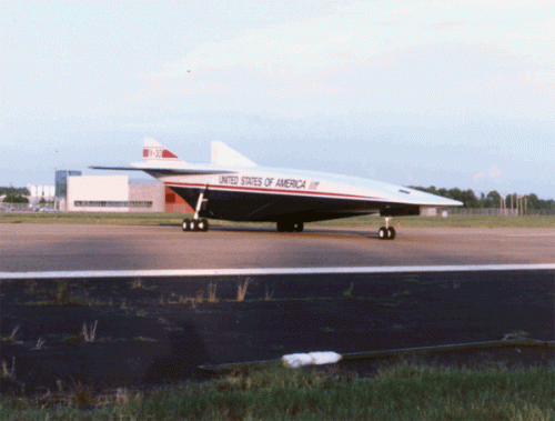
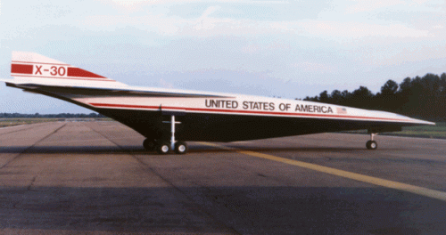
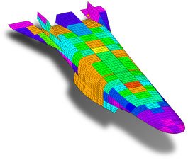
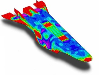
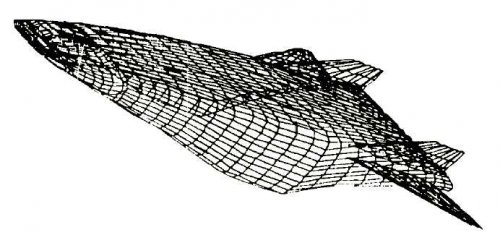
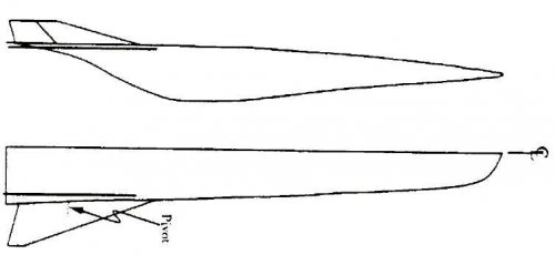
"An unclassified aeroelastic vehicle representative of the NASP configuration and referred to as the demonstrator model was developed []. A NASP configuration published in Aviation Week served as the basis for this model. A classified model, referred to as the NPO model, provided by the NASP National Project Office provided guidance for modifying the wing and vertical tail planforms and the wing root condition.The planform and profile of the resulting configuration are shown in [pictures 1 and 2]. The vehicle fuselage is 150 feet long and weighs approximately 300,000 lbs fully fueled with a center of gravity at approximately 56 % of the fuselage length. The root leading edge of the all-moveable clipped delta wing begins at 70% fuselage length. The wing has a root chord length of approximately 27% fuselage length, a span of approximately 9.5% fuselage length, a leading edgesweep of 70" and a trailing edge sweep of 15". The pivot shaft attaches at 65% of the wing root chord. The curved symmetric airfoil is thickest at 65% chord where the thickness is 4% of the local chord. The demonstrator model has twin vertical tails with rudders; the rudder is not modeled structurally. The profile view shows that the forward section of the fuselage acts as a compressor for the airflow as it approaches the engine and the aft portion of the fuselage acts as a nozzle for the engine exhaust."

"The model fuselage geometry was based on an unclassified configuration furnished by the NASP contractor team which is headed by the National Program Office (NPO). The NPO had subsequently decided in favor of an all-moveable wing and produced a classified FEM refferd as to the NPO model. A representative all-movable wing was, therefore, developed and included on the unclassified demonstrator FEM shown"

Later mutations include even aerospike engines installed on the boattail between vertical fins according to Scott Lowther aka OrionBlamBlam, that makes this 'final something' close to that ARSLS (Advanced Reusable Small Launch System) concept above.
 

Attachments

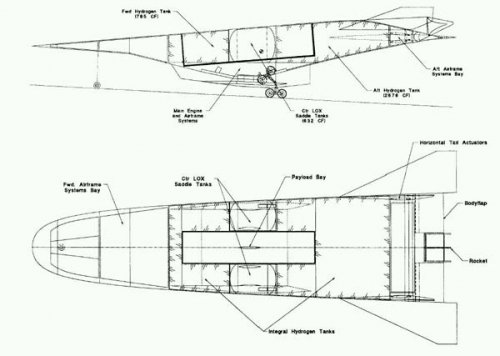
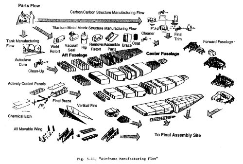
  • manflow.jpg
    manflow.jpg
    156.7 KB · Views: 552
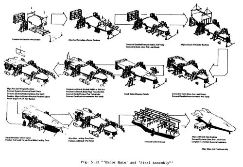
  • majormatefinalassembly.jpg
    majormatefinalassembly.jpg
    138.3 KB · Views: 700
  • Clipboard02.jpg
    Clipboard02.jpg
    36.8 KB · Views: 565
  • Clipboard01.jpg
    Clipboard01.jpg
    14.1 KB · Views: 541
For those who really addicted - 20 Mb, 570 pages of

Title: The Hypersonic Revolution. Case Studies in the History of Hypersonic Technology. Volume III: The Quest for the Orbital Jet: The National Aero-Space Plane Program (1983-1995)
AD Number: ADA441126 Corporate Author: AIR FORCE HISTORICAL STUDIES OFFICE BOLLING AFB DC Personal Author: Schwelkart, Larry Report Date: January 01, 1998 Media: 474 Pages(s) Distribution Code: 01 - APPROVED FOR PUBLIC RELEASE Report Classification: (Not Available). Source Code: 447256 From the collection: Technical Reports

http://stinet.dtic.mil/cgi-bin/GetTRDoc?AD=A441126&Location=U2&doc=GetTRDoc.pdf

Sometimes it really more detective reading than DaVinci Code, and at least I know how what the hell is 'DuPont Government Baseline' and what the hell duPont did in NASP project.
 
This really funny diagram from NASP ground maintenance subcontractor (Sverdrup) pic shows X-30 vehicle clearance.
Funny is the fact that while first I thought that it can give an idea of pretty exact X-30 dimensions, then I've read that Sverdrup developed them 'by scaling sketches published in the open literature which showed a typical X-30-sized vehicle ajacent to a Boeing 747.'
 

Attachments

  • x-30 vehclearance.jpg
    x-30 vehclearance.jpg
    61.6 KB · Views: 356
Boeing
Two design studies were completed, one was 'winged body', so-called government baseline, i.e. scaled-up duPont design, so basically all published illustrations if refered to this study is not far away from truth.
Later Boenig shifted to Langley-promoted conical accelerator, but entered a serious problems as result was VERY long vehicle with myriad stability/engine control problems. Boeing was downselected from competition.
 

Attachments

  • conical accelerator-s.jpg
    conical accelerator-s.jpg
    89.5 KB · Views: 374
  • 3v-s.jpg
    3v-s.jpg
    15.2 KB · Views: 365
  • earlynasp-.jpg
    earlynasp-.jpg
    118.8 KB · Views: 350
  • govbaseline.jpg
    govbaseline.jpg
    13.5 KB · Views: 370
Lockheed
Skunk Works started with a lifting body concept like MDC (attached image from Lockheed CFD-realted paper can give an idea of this studies), but then, trying to accelerate design processs, witched from integrating airfame and propulsion system to putting two huge engines on the sides of a vehicle, abandoning the whole idea of integrated vehicle. Lockheed relied on using not-so-sophisticated construction materials. Weight were growing (Lockheeed's craft being the heaviest NASP design reaching almost 400 000 lbs), and Lockheed guys used trick of launching vehicle using set of wheels that dropped off after take-off (not so far from Copper Canyon and duPont concepts of sled launch), with the landing 'glide-style' on vehicle's belly. The other detail known is that initially crew cabin should be close to the center of fuselage and later moved to the nose, that made aviable it's separation as part of crew rescue system. No images are avaible on this design so far. Not surprising that Lockheed was also downselected.
 

Attachments

  • locknaspearly.jpg
    locknaspearly.jpg
    19.2 KB · Views: 348
The McDD concept is undoubtedly the inspiration for many artists' "Aurora" concepts. The fact that McDD released these pictures publicly should tell us that Aurora DOESN'T look like these McDD drawings.

I have a pic of the McDD concept in FedEx markings. I can have it scanned and posted by January.

As for the "a202 configuration," was that an internal NASA design, or did a contractor come up with it?
 
Recently published AIAA paper has an insight of MDC and GDFW way to the BWB with spatula nose. As we can see, actual early MDC design wasn't so far from the artists' impressions spreaded in the media.

Hypersonic Boundary Layer Transition – Application to High Speed Vehicle Design
AIAA Paper 2007-0310, presented at 45th AIAA Aerospace Sciences Meeting, Reno NV, January 2007
Kei Y. Lau*
Advanced Global Strike Systems
Boeing Company
St. Louis, Missouri 63166

MDC

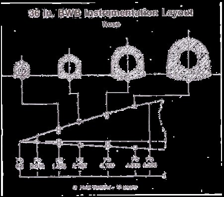
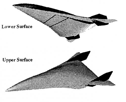
"In 1986, McDonnell Douglas won a contract under the NASP Technology Maturalization program to develop an experimental database for CFD validation, which was called the Generic Option 2 program. The database was to be used by the government team and the contractors for CFD development works. The shape for Generic Option 2 was chosen to be blended wing body (BWB) configuration derived from a MDC (McDonnell Douglas) design. The BWB configuration has a bi-elliptic cross section (second pic)... [Photo] shows the installation of the 36 inches aerothermal model in the Calspan 96-Inches Shock Tube Facility."
"The Generic Option 2 Aerothermal Test was very successful and generated a set configuration heating data from Mach 11 to 18 at flight Reynolds numbers. The test set includes configurations with sharp and blunt nosetips. It showed some puzzling boundary
layer transition behaviors that were not expected. At zero degree angle of attack, the sharp nose boundary layer transition onset occurred at the expected location. But the blunted nosetip did not move the onset location aft. When the angle of attack was
increased, the sharp nose onset location moved forward and the blunt nose onset location moved aft.
Additional test runs were conducted using distributed roughness strips at nose location. The strip usually worked very effectively on cones at the Calspan tunnels. It tripped the sharp nose boundary layer, but had no effect on the blunted configuration. The early
transition onset with the blunt nose is obviously not an artifact of tunnel noise. An explanation was needed to understand the transition behavior of this class of configuration.
The blunt nose puzzle was resolved after an extensive CFD and boundary layer rack data study. The bi-elliptic forebody was optimized using method of characteristic and streamline tracing during the configuration development. There was no crosstalk
between upper and lower surfaces in sharp configuration analysis. The blunted nosetip was addition for thermal protection purpose afterwards.
The introduction of the blunt nose caused strong crossflow on the windward surface that resulted in flow bi-focation along windward centerline and a thick boundary layer built-up. The crossflow bifocation de-stabilized the boundary layer and caused very early transition along the windward centerline. The crossflow diminished with increasing angle of attack and allowed the onset to move aft. At the nominal design angle of attack of 4 degrees, the blunt nose had a small effect in delaying transition onset compared to the sharp nose data, but the result nonuniformity of boundary layer circumferentially is causing drag increase and inlet performance impact.
In late 1986, the MDC NASP program established a tiger team to investigate the scramjet engine to airframe integration. In addition to mechanical issues, the figure of merits included propulsion performance, vehicle controllability, boundary layer control, thrust
vs. drag trade-off, inlet performance and flight angularity sensitivity. The lessons learned from Generic Option 2 test program on the difficulty in boundary layer control of a bi-elliptic shape was one of the consideration when MDC made a major configuration switch to a Non-circular-body (NCB) design.
In 1987, Beckwith reported difference in boundary layer transition onset between wedge and cone to NASP symposium at AMES based on an earlier AIAA paper he published on quiet flow tunnel design <...> The discovery helped affirm the decision to further develop the NCB configuration by the McDonnell Douglas NASP team. This configuration eventually evolved into the NASP
forebody shape as we know it today.

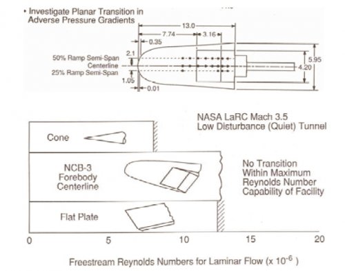
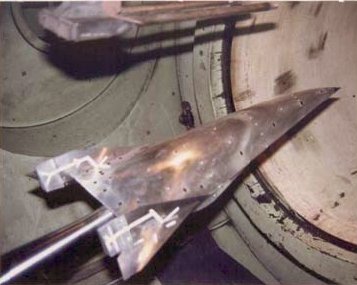
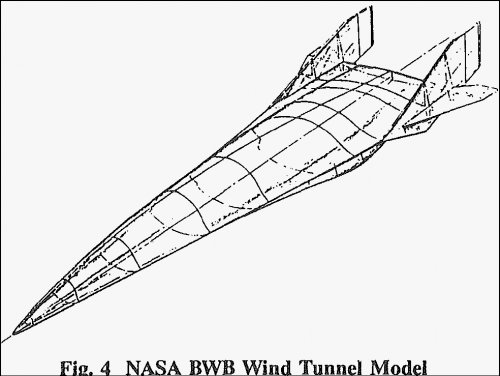
In the late 1980’s, two sets of configuration boundary layer transition database were created by the contractors. The McDonnell Douglas tested with an early NCB (Non-Circular Body) design Configuration to gain more insight into boundary layer transition behavior of planar flow. The model was built of machined solid stainless steel block and micro-polish to better than 1 micron finish. Surface mounted pitot tube was used for transition onset detection. The test successfully demonstrated that the NCB configuration behaved like a wedge in transition onset. < Third pic> shows the MDC test model."

GD(FW)
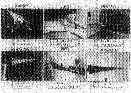
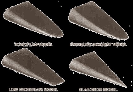
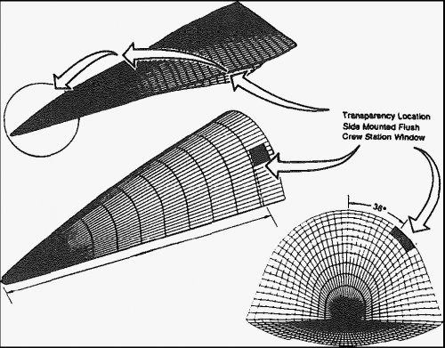
"The General Dynamic-Fort Worth team took a different approach and tested four generic configurations. <Fourth pic> shows the GD-FW test models.
 

Attachments

  • NASP GD-FW Contractor BLT Test at Mach 3.5 Quiet Tunnel.jpg
    NASP GD-FW Contractor BLT Test at Mach 3.5 Quiet Tunnel.jpg
    68.7 KB · Views: 280
  • NASP MDC Contractor BLT Test at Mach 3.5 Quiet Tunnel.jpg
    NASP MDC Contractor BLT Test at Mach 3.5 Quiet Tunnel.jpg
    114.9 KB · Views: 255
  • NASP Generic Option 2 BWB Model CS.jpg
    NASP Generic Option 2 BWB Model CS.jpg
    78.8 KB · Views: 264
  • NASP Generic Option 2 Aerothermal.jpg
    NASP Generic Option 2 Aerothermal.jpg
    75.2 KB · Views: 305
Found sevaral more MDC Generic Option 2 Aerothermal Test configuration pics.
 

Attachments

  • NASP Generic Option 2 topbottom.jpg
    NASP Generic Option 2 topbottom.jpg
    114.1 KB · Views: 305
  • NASP Generic Option 2iso.jpg
    NASP Generic Option 2iso.jpg
    142.1 KB · Views: 290
  • NASP Generic Option 2profile.jpg
    NASP Generic Option 2profile.jpg
    133.7 KB · Views: 244
  • NASP Generic Option 2crewstwind.jpg
    NASP Generic Option 2crewstwind.jpg
    348.1 KB · Views: 294
CFE said:
As for the "a202 configuration," was that an internal NASA design, or did a contractor come up with it?

a202 was unified contractors/NASA design, a symbiosis of best design concepts
 
Found some better quality GD NASP publicity leaflet
 

Attachments

  • scan0119.jpg
    scan0119.jpg
    355.9 KB · Views: 433
  • scan01201.jpg
    scan01201.jpg
    468.5 KB · Views: 387
How much would the technology help the commercial/private aircraft business if it was declassified today? I can understand keeping SOME things secret but why haven't these kind of air/spacecraft materialized into the public domain for commercial use? Maybe I just have a hard time understanding government bureacracy and secrecy. Or maybe I just don't plain trust them. :mad: :(
 
John21 said:
How much would the technology help the commercial/private aircraft business if it was declassified today? I can understand keeping SOME things secret but why haven't these kind of air/spacecraft materialized into the public domain for commercial use? Maybe I just have a hard time understanding government bureacracy and secrecy. Or maybe I just don't plain trust them. :mad: :(

Because this kind of stuff is probably more useful militarily than commercially. They can't even make Mach 1.5 commercially viable let alone Mach 25.
 
This is Lockheed NASP configuration with podded scramjet engines. Various engine modules number and position were studied, but the core idea was moving scramjet modules off the fuselage.
 

Attachments

  • LockNASPpodded.jpg
    LockNASPpodded.jpg
    32.2 KB · Views: 540
Last edited:
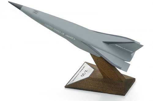
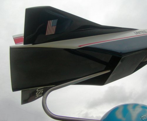
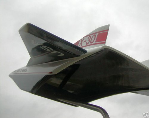
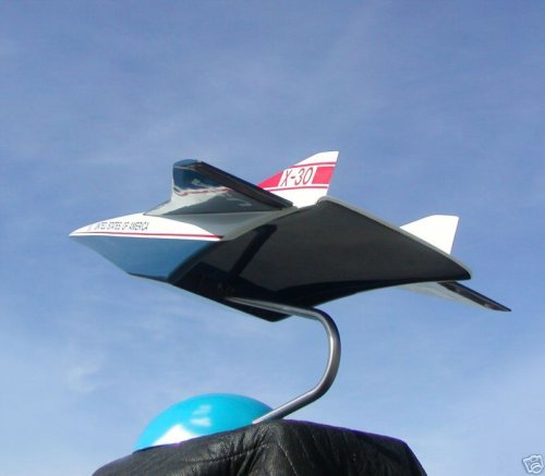
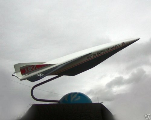
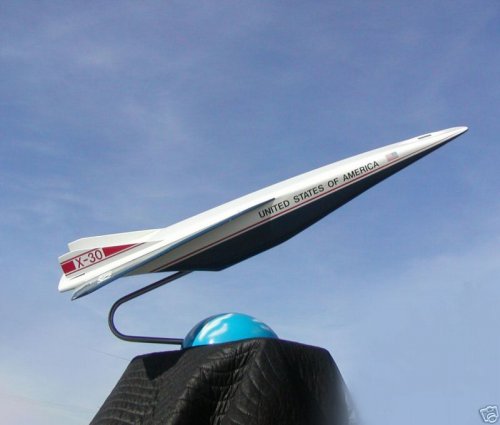
'Unified' X-30 a202 configuration publicity desktop model
 

Attachments

  • 02a9_3.jpg
    02a9_3.jpg
    45 KB · Views: 284
  • 01dd_3.jpg
    01dd_3.jpg
    39 KB · Views: 256
  • 1073_3.jpg
    1073_3.jpg
    43.2 KB · Views: 246
  • 114e_3.jpg
    114e_3.jpg
    41.4 KB · Views: 239
  • 0175_3.jpg
    0175_3.jpg
    41.9 KB · Views: 365
  • 6256_3.jpg
    6256_3.jpg
    45.9 KB · Views: 387
  • 024b_3.jpg
    024b_3.jpg
    44.5 KB · Views: 368
  • 3dfc_3.jpg
    3dfc_3.jpg
    44.3 KB · Views: 427
This can give an rough idea of X-30, configuration a202, dimensions
 

Attachments

  • x-30_vehclearance.jpg
    x-30_vehclearance.jpg
    61.6 KB · Views: 235
flateric, quoted: "This can give an rough idea of X-30, configuration a202, dimensions"

Is that the plane or the engine nacelle?
 
It's the Sverdrup report on 'final' NASP configuration ground equipment clearance, so it's the FULL airframe inscribed in these dimensions.
As final configuration is 'classified' that's all they could show.
 
Oh, looks nice, but in fact you could try this - this is more close to the real stuff, (especially the second one), than this FI drawing based on AWST cover.
 

Attachments

  • X-30-roundwedgenose.jpg
    X-30-roundwedgenose.jpg
    29.2 KB · Views: 248
  • Clipboard01.jpg
    Clipboard01.jpg
    14.1 KB · Views: 249
Okay, now I see. The NASP you show is from the mid- or late-80's. More recent university AIAA competition(held every year) designs look substantially different according to differing views as to possible aerodynamic efficiency and CAD software available or employed in the research process.
 
There was just one NASP that I know that went to grave ca.1994. This is semi-final design (OK, final design is classified) from ca.1992. What the connection between university AIAA competitions and this, quite specific, program?
 

Similar threads

Please donate to support the forum.

Back
Top Bottom