You are using an out of date browser. It may not display this or other websites correctly.
You should upgrade or use an alternative browser.
You should upgrade or use an alternative browser.
Variable Geometry Tail Fin of the Aircraft
- Thread starter hesham
- Start date
- Joined
- 27 May 2008
- Messages
- 1,176
- Reaction score
- 2,474
Yes, the tail area is normally set by the requirement to control yaw in the event of an engine failure at take off and/or go around (engines at max thrust). Once you’re in cruise, with the engines at a much lower power setting, that extra fin area just produces needless drag and with it fuel burn. What’s stopped the adoption of this is their cost/complexity against the relatively low fuel prices…. But in future it might just happen.
Last edited:
archipeppe
ACCESS: Top Secret
- Joined
- 18 October 2007
- Messages
- 2,427
- Reaction score
- 3,119
- Joined
- 13 August 2007
- Messages
- 8,367
- Reaction score
- 10,749
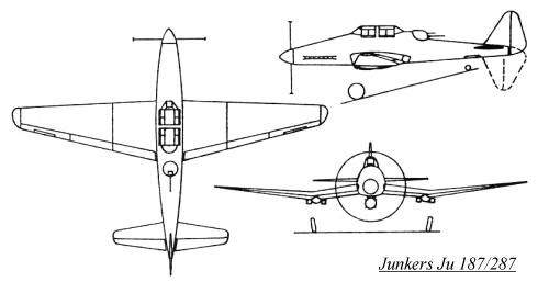
Junkers JU 187/287 is special case
It's dive-bomber who use a rotating tail fin for easier dive.
However i don't know how they solve the issue with controls for 180° rotating tail fin...
It's dive-bomber who use a rotating tail fin for easier dive.
However i don't know how they solve the issue with controls for 180° rotating tail fin...
Manuducati
ACCESS: Secret
- Joined
- 25 November 2020
- Messages
- 323
- Reaction score
- 1,006
Junkers JU 187/287 is special case
It's dive-bomber who use a rotating tail fin for easier dive.
However i don't know how they solve the issue with controls for 180° rotating tail fin...
The rotating tail was - as far as I'm aware - only linked to the rear gunner field of fire, not to aerodynamic considerations. I could be wrong of course.
- Joined
- 15 February 2024
- Messages
- 488
- Reaction score
- 1,282
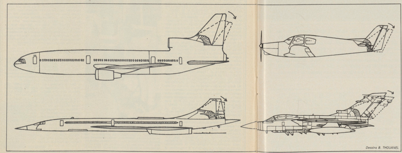
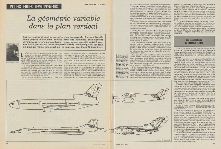
Of course not: it's an April fool publication.From Aviation magazine 1-4-1983,
was that a real research ?.
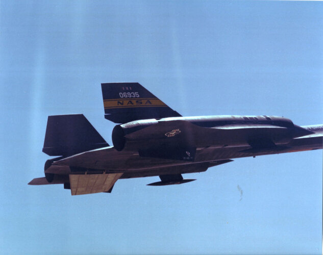
Not like this one: (NASA photos)
Attachments
- Joined
- 27 December 2005
- Messages
- 17,665
- Reaction score
- 25,710
1-4-1983 - 1st April...From Aviation magazine 1-4-1983,
was that a real research ?.
There have been variable geometry horizontal tail studies however.
- Joined
- 19 February 2007
- Messages
- 1,430
- Reaction score
- 2,647
The Lockheed Jetstar had a vertical stabilizer hinged as seen above albeit with a much more limited range of motion. The reason was to provide trim motion to the horizontal stabilizer which was fixed to the moving vertical stabilizer.
Avimimus
ACCESS: Top Secret
- Joined
- 15 December 2007
- Messages
- 2,395
- Reaction score
- 852
Mig-23 has a vertical stabiliser which folds (but this is to allow take-off and landing). I find it interesting that its tail area is actually less during landing than during normal flight. So it has been done.
I did some rather crude experiments in X-Plane a few years back with a retracting horizontal stabiliser. The aircraft had a relatively long fuselage. Once trimmed for cruise I could reduce the stabiliser area and get close to a 5% increase in range (if I recall correctly). If encountering turbulence or needing to manoeuvre I could extend the elevator back out. IRL this is probably a bad ideas, and at the very least one would want to make sure any system failure would cause the elevator to automatically extend. The weight increases from the folding mechanism might also reduce any benefits.
That said, a lot of elevator authority is used just for the take-off rotation (and to a lesser extent to ensure a safe margin of control during landing)... so having something like a retractable fixed incidence auxiliary elevator (to provide more static stability and centre it around a different trim position) might make sense in some designs... I don't think it can be ruled out entirely.
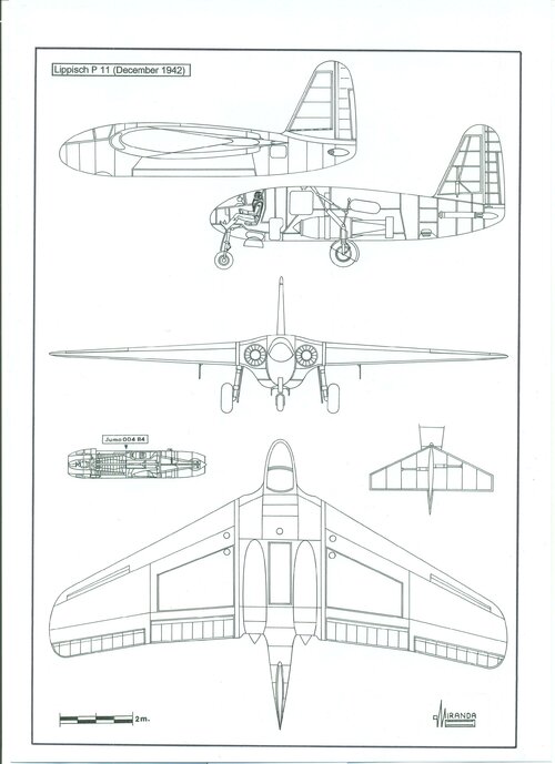
Lippisch P.11
In October 1941 it was evident that the rocket engines planned for the Me 163 B would take months or even years to be available.
By the beginning of the month, the excellent aerodynamic features of the Me 163 A had allowed it to reach 1,000 km/h (0.84 Mach) and Alexander Lippisch started to consider the possibilities of the new Junkers T1 turbojets that had been successfully tested some days after the record was achieved.
They were too long for a Komet airframe. They should be installed in a bigger airplane, a heavy fighter of six tons, equivalent to the Me 262 that, with the Me 163 aerodynamics, would have better ceiling, climb rate and max speed.
On 28 November 1941 it was presented to the OKL, as Lippisch P.09, a single seat heavy fighter armed with four 20 mm guns. Too advanced for its time, when the Me 163 had not yet engaged in combat, it was decided to favour the manufacturing of the Me 262.
Lipisch decided to modify the basic design as schnellbomber, by installing a second crew member, widening the wingspan 1.4 m and reducing the sweep 3-degrees. The fuselage contained two fuel tanks and a bomb bay underneath them with capacity for an SC 1000 L2.
The new project, known as Lippisch P.11-92 13/09/42, was presented to the OKL as the answer to the specification published by the RLM’s Technical Department on October 20, 1942. It required a bomber with 1,000 kg payload, 700 km/h max speed and 1,046 km penetration depth.
It did not turn out well. Designers had not considered that the acceleration generated by the turbojet was much too lower than the rockets on which the original project was based. It was estimated that a tailless bomber, heavy loaded, would have had difficulties to make the rotation during the take-off, due to the short distance between the elevators and the centre of gravity, even supported by the RATO auxiliary rockets. The P.11-92 was cancelled in November 1942.
On 2nd December, the design team of the Abteilung L (Lippisch) tried again with an improved design (P.11-105) that replaced the radio operator by new electronic equipment for fighters. The cockpit was installed in the nose to reduce the drag produced by the old canopy and the climb rate and ceiling were improved, increasing the wing surface. To solve the problem of the take-off, it was installed a retractable tailplane formed by two trapezoidal surfaces of 3 sq. m each.
The P.11-105 could dive bomb using a Revi C16 reflector gunsight or at high altitude in a flight levelled with the Lofte 7 bombsight. The idea of the retractable tailplane was not liked by OKL who, considering the aircraft unstable, cancelled the project at the beginning of 1943. Instead, production of Me 410 B-1 was initiated.
Abteilung L was dissolved within the Messerchmitt in April and the Lippisch design team moved to Vienna to form the Aeronautical Research Institute Luftfahrtforschungsanstalt Wien. The works on the P.11 continued there, introducing for the first time the `jet-exhaust deflection flaps´ effect, aerodynamic surfaces located behind the engines that, changing the angle of incidence by hydraulic actuators, helped to maintain the tail low during take-off.
Attachments
- Joined
- 11 March 2012
- Messages
- 3,245
- Reaction score
- 3,154
Similar to the Mooney M-20 series of light, 4-seater singles. The vertical and horizontal stabilizers were rigidly attached, so when the pilot wanted to tilt the horizontal stabilizer to adjust pitch trim, he also changed the forward sweep on the vertical fin. This tilt made little difference to airflow around the vertical fin and rudder, but did contribute to unique appearance.The Lockheed Jetstar had a vertical stabilizer hinged as seen above albeit with a much more limited range of motion. The reason was to provide trim motion to the horizontal stabilizer which was fixed to the moving vertical stabilizer.
- Joined
- 11 March 2012
- Messages
- 3,245
- Reaction score
- 3,154
Fast forward to the 6th generation stealth fighters that are currently on the drawing board and many are sketched without any vertical tails. This is to reduce their radar signature when scanned from the side. We are guessing that they will us wing-tip drag-rudders (ala. B-2 stealth bomber) to adjust yaw.
Keep in mind that they might still need aerodynamic rudders for slow-speed landings and take-offs, so might benefit from retractable fins.
Would it be enough to lay the fin on its side on top of the broad fuselage?
Another option - for yaw control - is swivelling engine nozzles.
Keep in mind that they might still need aerodynamic rudders for slow-speed landings and take-offs, so might benefit from retractable fins.
Would it be enough to lay the fin on its side on top of the broad fuselage?
Another option - for yaw control - is swivelling engine nozzles.
I have felt that some type of adaptive wing would be an interesting 6th gen feature. Change the wing type based on the profile required but in an easier to accomplish way than the swing wing generation.Fast forward to the 6th generation stealth fighters that are currently on the drawing board and many are sketched without any vertical tails. This is to reduce their radar signature when scanned from the side. We are guessing that they will us wing-tip drag-rudders (ala. B-2 stealth bomber) to adjust yaw.
Keep in mind that they might still need aerodynamic rudders for slow-speed landings and take-offs, so might benefit from retractable fins.
Not if the aircraft wants to achieve the VLO level expected of a 6th Gen platform.Would it be enough to lay the fin on its side on top of the broad fuselage?
Possible but again there might be RCS considerations.Another option - for yaw control - is swivelling engine nozzles.
Similar threads
-
-
Russian-Aircraft Variable-Geometry Inlet Use (Cold-War Predominantly)
- Started by KJ_Lesnick
- Replies: 6
-
-
Burns Aircraft Company BA-42 light aircraft prototype......
- Started by Caravellarella
- Replies: 19
-

