
You are using an out of date browser. It may not display this or other websites correctly.
You should upgrade or use an alternative browser.
You should upgrade or use an alternative browser.
the history of (unbuilt) jet canard aircraft
- Thread starter Norse
- Start date
- Kyushu J7W1 Shinden
Throughout aviation history there have been designs of the ‘canard’ or ‘tail first’ types as an alternative to the conventional ‘engine first’ configuration. However, despite the creativity of designers, manufacturers have systematically left aside the mass production of such solutions. When the second generation of fighters designed during the WWII started to experiment serious aerodynamic problems, due to the transonic flux, they made several tries to solve them using the ‘canard’ configuration to eliminate airscrew slipstream effects on aircraft drag.
The British firm Miles built, and fly tested, the M.35 and M.39B prototypes as technological demonstrators of the M.39 bomber. The German Henschel designed the heavy fighter named P.75 that should be propelled by a DB 613 A/B coupled engine and which mass production was abandoned in favour of the Dornier Do 335. Several prototypes of ‘canard’ fighters were built in Italy and USA.
The ‘canard’ formula had many advantages for the design of fighters; the armament could be grouped around the nose without any hindrance by either the engine or the propeller and it was very easily accessible for maintenance, ground visibility was considerably improved and it was easier to install a tricycle type undercarriage. The engine, located behind the pilot, acted as protection against the rear impacts and, in the event of a fire, flames did not go to the cockpit as used to happen with the classical designs. Besides, being joined to the main spar meant less weight and stronger structural sturdiness.
In combat, an enemy pilot not familiar with the new configuration could easily mistake the direction to which the canard fighter moved during the deflection aiming. Same tactic is used by some tropical fishes that have a spot in the shape of a false eye near the tail to confuse their predators. Only two inconveniencies marred all the advantages: the difficulty to refrigerate the engine and the baling out, due to the position of the pusher airscrews.
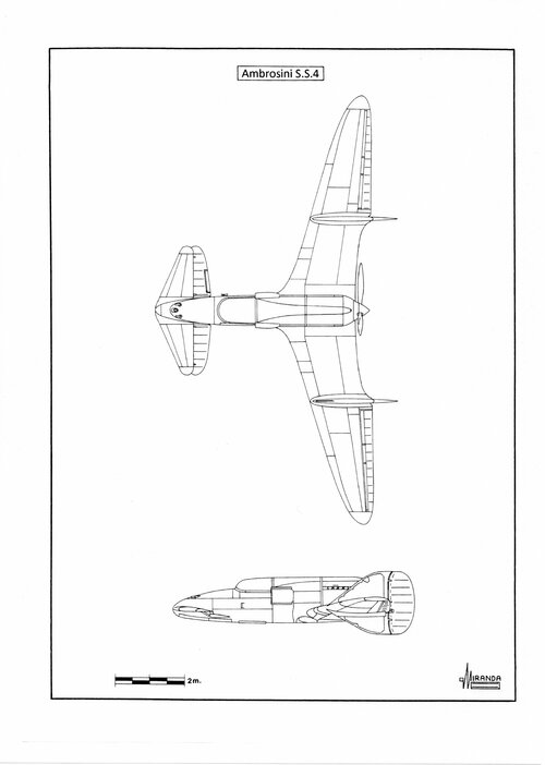
At a time when ejector seats did not yet exist, the solution was to install an explosive device to detach the propeller in case of emergency. Early in 1939 the Italians built the Ambrosini S.S.4 a ‘canard’ prototype fighter powered by one 960 hp Isotta Fraschini Asso XI RC.40 engine. The airplane was destroyed in 1941 due to a problem of vibration of the engine mount and the project was cancelled.
On 21 December 1941, the ‘canard’ prototype Curtiss CW-24B made its first flight, at Muroc air base, powered by a 275 hp Menasco C-6S-5 engine. Despite the strong security measures, intelligence services of the IJN obtained enough information about the project to believe that it was the successor of the Curtiss P-40 fighter. In fact, the definitive Curtiss XP-55 version was not selected by USAAC for production and only three prototypes were built, two of which were destroyed in accidents.
Americans were not lucky with the Curtiss XP-55. After four years of flight testing, they have not achieved an airplane sufficiently stable to take part in combat operations. Although it was less sensible to the compressibility buffeting than conventional airplanes, thanks to a NACA 0015 type wing profile, it was also too heavy and slower than the P-47 and P-51 in service.
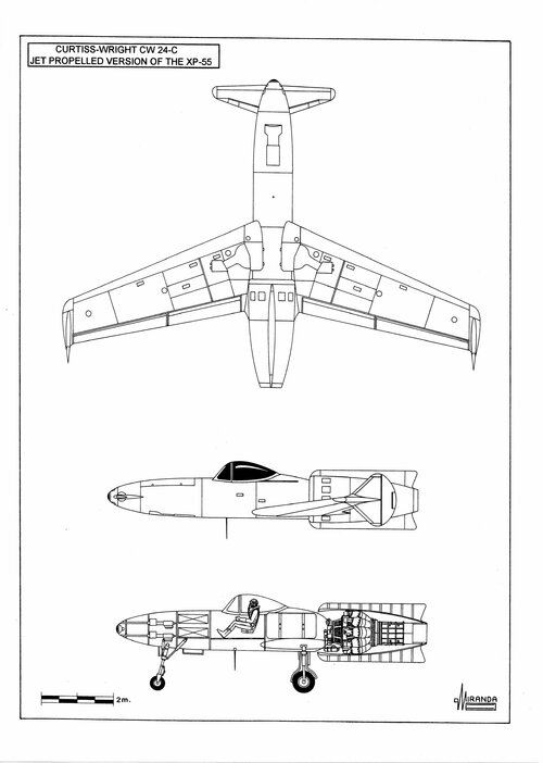
Before cancelling the project, the Curtiss firm proposed the production of a jet version based on the original P 249-C project, known in the specialised literature as P 286-17 or CW 24-C. It would have been propelled by a centrifugal De Havilland H-1B Goblin turbojet with a fuel tank of 1,059 lt., located behind the pilot, and armed with four 0.50 calibre M2 machine guns. Its mass production was abandoned in favour of the Lockheed P-80.
To meet the IJN requirements of 1943, (18-shi-Otsu non-official specification) calling for a land-based, high-performance interceptor able to counter the new Allied fighters, Nakajima proposed the twin engine J5N1 Tenrai and Kawasaki the J6K1 Jinpu. Early in 1943 Lieutenant Commander Masaoki Tsuruno, of the First Naval Air Technical Arsenal, proposed the construction of a 18-shi-Otsu ‘canard’ fighter based on the information obtained on the XP-55.
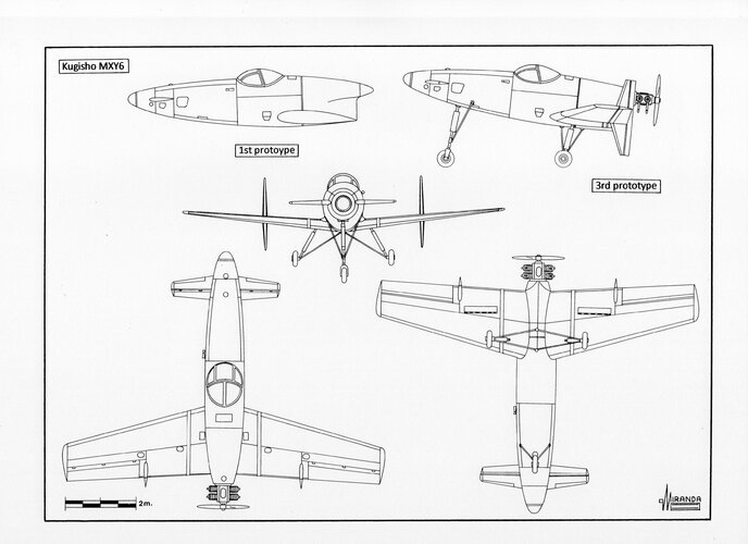
The Kaigun Koku Hombu ordered the firm Chigasaki Seizo K.K. the construction of three wooden experimental gliders MXY6, with ‘canard’ lifting surfaces, to prove the feasibility of the concept. Glider tests, towed by one Nakajima B5N bomber, began at Yokosuka in the fall of 1943, demonstrating good flight characteristics. One of the prototypes was finally fitted with a 22 hp Nihon Semi Ha-90/11 four-cylinder-boxer, air-cooled engine, driving a two-bladed wooden airscrew from a Kugisho MXY4 anti-aircraft target.
In 1945 the MXY6 was proposed to the IJN as a prototype suicide plane, but the project was not carried out because of the priority given to the construction of the Showa Toka bomber.
MXY6 3rd prototype technical data
Wingspan: 9.14 m, length: 7.3 m, height: 2.95 m, wing area: 17 sqm, max weight: 500 kg, max speed: 320 kph.
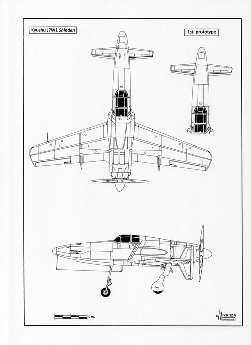
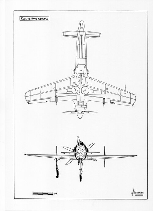
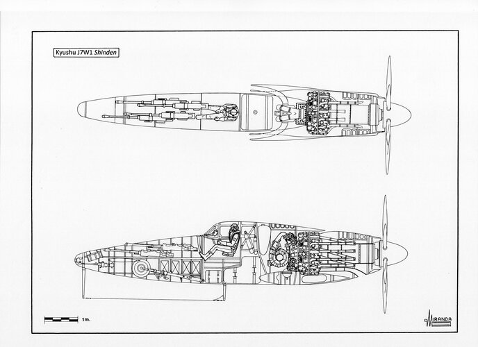
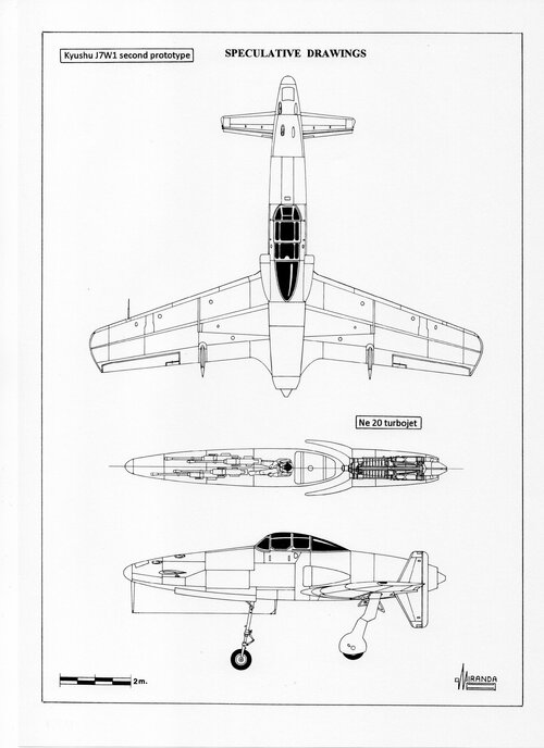
After a promising MXY6 tests, the Kaigun Koku Hombu ordered the Kyushu Hikoki K.K. (Watanabe Tekkosho) to design a high-performance ‘canard’ interceptor. One 1/6 scale wind tunnel model was tested by September 1944. Construction of the X-18/J7W1 prototype, equipped with laminar flow wings with maximum thickness located 45 per cent chord, had already begun on June 4 and was completed in April 1945. The engine selected by the IJN was a 2,130 hp Mitsubishi MK9D (Ha-43-42) radial engine, (without the torque converter of the Ha-43-21) with two speed mechanical first stage and Vulkan coupling second stage, Methanol injection and forced cooling fan. The pusher propeller was one Sumitomo/VDM six-bladed, constant-speed with 3.4 m of diameter.
It was decided that the production version would be armed with four Type 5, 30 mm cannon with 60 r.p.g. and two Type 100, 7.92 machine guns. Pilot protection would consist of one 70 mm thick armoured glass windshield and one anti-bullet board armour plate with 16 mm thickness. The first flight of the prototype took place on 3 August 1945. During testing the plane suffered cooling problems while running the engine still on the ground, the powerful MK9D generated a great deal of torque and the airplane pulled hard starboard at take off. Small retractable wheels were added to the base of each fin to prevent tail damage upon landing. In flight the prototype showed strong vibrations in the propeller and its extended drive shaft. The IJN expected a production of 150 aircraft per month during 1946, built by Kyushu and Nakajima, but the construction of the second prototype was not completed.
J7W1 technical data
Wingspan: 11.114 m, length: 9.76 m, height: 3.555 m, wing area: 22.9 sq.m, max weight: 4,928 kg, max speed: 750 kph, service ceiling: 12,000 m.
When the first jet engines were available, the designers realized that the new power plant was ideal for the ‘canard’ fighters (less heavy than the twin booms of the Vampire type, SAAB J-21 and Vultee XP-54 and more stable than the Northrop XP-56 flying wing). Given time the refrigeration conducts designed for the piston engine converted into air intakes for the jet engine.
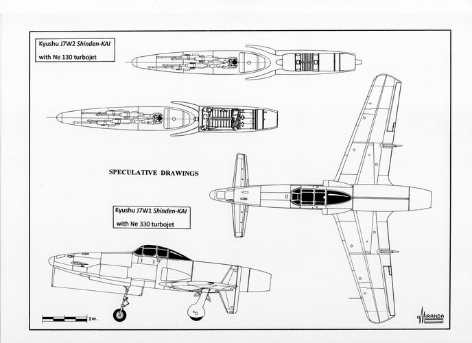
The Kyushu firm designed a jet version of the J7W1 Shinden known as J7W2 Shinden-KAI (not official name), propelled by one Ne 130 axial flux turbojet with 900 kp of thrust. The second prototype would have been possibly completed with a Ne 20 turbojet, the only one available, for flight testing. Removing the propeller would have made the use of a large landing gear unnecessary and the J7W2 would have use a smaller landing gear. Would the end of WWII have not precipitated it could have been a formidable adversary for the B-29s.
J7W2 technical data
Wingspan: 11.114 m, length: 9.76 m, wing area: 22.9 sq.m, max weight: 4,930 kg, max speed: 800 kph.
Attachments
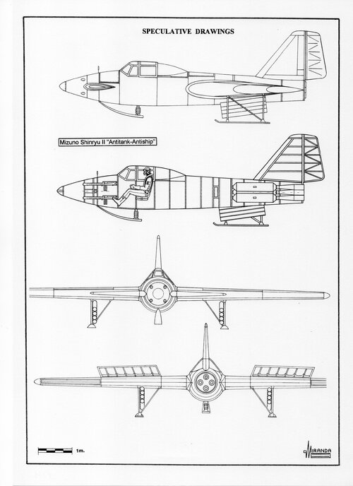
Mizuno Shinryu II
Grabbing the opportunity of having the new rocket engines developed by the IJN to propel the Ohka, the engineers of Mizuno decided to develop their own rocket glider.
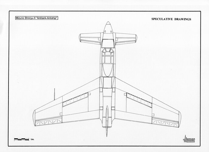
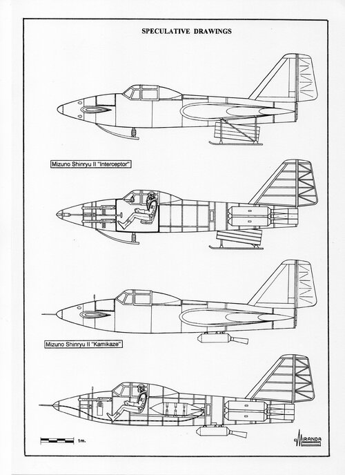
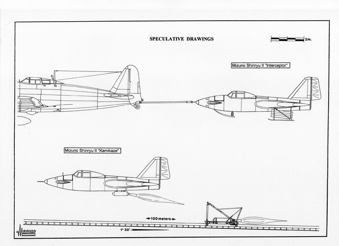
It had an unusual ‘Canard’ configuration to facilitate the short take off and it was built of wood, plywood and iron plate, with four Type 2 rocket engines at the rear of the fuselage. Three different versions would have been manufactured: kamikaze, antitank and interceptor. The suicide version had no undercarriage, using the same rails and rocket cart system than the Ohka 43-Otsu for take-off. It would have been able to carry a bomb of 250 kg in the fuselage, behind the pilot.
Like the suicide bombers D4Y4 Suisei and the Type 5 Shinyo motorboats, the Shinryu II would have possibly been equipped with two or four barrage I.S.R. rockets of 12 cm that would have made more difficult for the enemy gunners to reach the target during the terminal dive.
The anti-tank version took off by its own means over a primitive landing gear of skids, helped by a Type 1 ventral rocket that was detachable. It is assumed that it had the four rocket engines in the fuselage to maintain its flight altitude during the attack. It used eight anti-armour hollow charge ROTSU rockets of 8 cm, housed in iron tubes welded to the undercarriage, with a minus 7 degree pitch so that they could be shot without losing any altitude or speed. The airplane had spoilers and it was expected to survive to be able to land and refuel for the next attack.
Although this version has been described as anti-tank, as it used that type of armament, it seems more realistic to assume that it would have been used to attack the LCA. The interior of the island would have had thousands of suicide commands waiting for the Sherman tanks with magnetic demolition charges of 10 kg of the ‘lung mine’ type.
The interceptor was equipped with oxygen, pressurised cockpit and reflex gunsight. It was towed by a conventional piston fighter that took it off above 8,000 m releasing it over the stream of bombers. It was armed with eight Ro.3 rockets that exploded by means of a time fuse at a predetermined distance, releasing shrapnel and incendiary pellets in a conic pattern.
Like its German counterpart W.Gr 21, the Ro.3 was not very accurate and lost altitude very fast. For that reason, the launching tubes were fixed at a plus 7 degree pitch, calculated so that the parabolic path of the rocket would be compatible with the performance of the reflector gunsight.
All versions of the Shinryu II had machine guns with ammo tracer to help the correction of the attack trajectories. These would also be of use to the interceptor to defend from the escort fighters, evade them thanks to its manoeuvrability and return to base on a gliding flight. The four rocket engines, started sequentially, would serve it to regain altitude after an attack over the formation of B-29s or to distance away from the escort fighters.
Technical data
Airframe: wood, fabric and iron plate; Wingspan: 10 m; Length 7.80 m in the interceptor version; Height: 2.70 m; Wing area: 19 sq.m; Maximum speed: 500 kph in the kamikaze version; Ceiling: over 8,000 m in the interceptor version; Range: 15 km in the kamikaze version; Engines: four Toku-Ro.1 Type 2 with 600 kg peak thrust during 30 sec. In the anti-tank and kamikaze version another Toku-Ro.1 Type 1 was used with 300 kg peak thrust during 10 sec, in ventral position, to provide additional boost during take off. Armament: four Type 89 7.7 mm guns that were reduced to two in the kamikaze version. Eight Ro.San Dan (Ro.3) 10 cm S.C.R. AA rockets in the interceptor version, eight ROTSU 8 cm S.C.R. hollow charge rockets in the ant ship/antitank version, two or four RAK 12 cm I.S.R. barrage rockets and one 248,7 kg Type 99 Number 25 Model 1 bomb in the kamikaze version.
Attachments
Curtiss XP-55
On 27 November, 1939 the USAAC announced the competition ‘Request for data R-40C’ for a very high performance fighter that should be equal to the new European models, to be built in 1941.
The Air Corps Interceptor Pursuit Specification XC-622, required:
Single-engine, single-seater with a top speed of at least 425 mph at 20,000 ft, sufficient to attack or leave combat area at will.
Seven minutes to climb to 20,000 ft.
Good pilot visibility
Four guns armament
Enough maneuverability
One and half hours endurance
The 2,000 hp, 24 cylinder ‘H’, liquid-cooled Pratt & Whitney X-1800-A3G engine was initially proposed.
Curtiss proposed the P-248-01design, an Allison powered CW-21 Demon and the CW-24, an unorthodox tailless-canard fighter, with 45 degrees swept-back wings and pusher propeller.
Around fifty projects were presented by nine different companies. By the end of 1940 six of them had been selected: Vultee (XP-54), Curtiss Wright CW-24 (XP-55), Northrop (XP-56), MacDonnell (Mod 1), Republic (AP-12) and Bell (Mod 13).
The first three qualified ones were never mass manufactured because they were of a too radical pusher design, making a failure of the whole $ 6,000,000 programme.
Throughout aviation history there have been designs of the canard or ‘tail-first’ types as an alternative to the conventional ‘engine-first’ configuration. However, in spite of the creativity of designers, manufacturers have systematically left aside the mass production of such solutions. When the second generation of fighters designed during the Second World War started to experiment serious aerodynamic problems, due to the transonic flux, they made several tries to solve them using the canard configuration eliminating airscrew slipstream effects on aircraft drag.
With this new configuration the designers tried to elude the problem of compressibility buffeting by installing the wing behind the center of gravity.
The British firm Miles built and fly tested the M.35 and M.39B prototypes as technological demonstrators of the M.39 bomber.
The German Henschel designed the heavy fighter named P.75 that should be propelled by a DB 613 A/B coupled engine and which mass production was abandoned in favor of the Dornier Do 335.
Several prototypes of canard fighters were built in Italy and USA.
The canard formula had many advantages for the design of fighters; the armament could be grouped around the nose without any hindrance by either the engine or the propeller and it was very easily accessible for maintenance, ground visibility was considerably improved and it was easier to install a tricycle type undercarriage.
The nose foreplanes had been found to serve the purpose of improving take-off performance and low speed control.
The engine, located behind the pilot, acted as protection against the rear impacts and, in the event of a fire, flames did not go to the cockpit as used to happen with the classical designs. Besides, being joined to the main spar meant less weight and stronger structural sturdiness.
In combat, an enemy pilot not familiar with the new configuration could easily mistake the direction to which the canard fighter moved during the deflection aiming. Same tactic is used by some tropical fishes that have a spot in the shape of a false eye near the tail to confuse their predators.
Only two inconveniencies marred all the advantages: the difficulty to refrigerate the engine and the baling out, due to the position of the pusher airscrews. At a time when ejector seats did not yet exist, the solution was to install an explosive device to detach the propeller in case of emergency.
Early in 1939 the Italians built the Ambrosini S.S.4 a canard prototype fighter powered by one 960 hp Isotta Fraschini Asso XI RC.40 engine. The airplane was destroyed in 1941 due to a problem of vibration of the engine mount and the project was cancelled.
On 22 June 1940 the USAAC signed a contract for preliminary development of the Curtiss CW-24 and construction of a wind tunnel model, under the designation XP-55.
Such a radical configuration required the construction of the CW-24B, a flying testbed to prove the design viability.
On 21 December 1941 the CW-24B made its first flight, at Muroc Dry Lake test center, powered by a 275 hp Menasco C-6S-5 engine.
Despite the strong security measures, intelligence services of the IJN obtained enough information about the project to believe that it was the successor of the Curtiss P-40 fighter. Early in 1943 Lieutenant Commander Masaoki Tsuruno, of the First Naval Air Technical Arsenal, proposed the construction of the canard fighter 18-shi-Otsu J7W Shinden based on the information obtained on the XP-55.
In fact, the definitive Curtiss XP-55 version was not selected by USAAC for production and only three prototypes were built, two of which were destroyed in accidents.
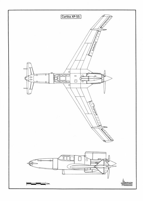
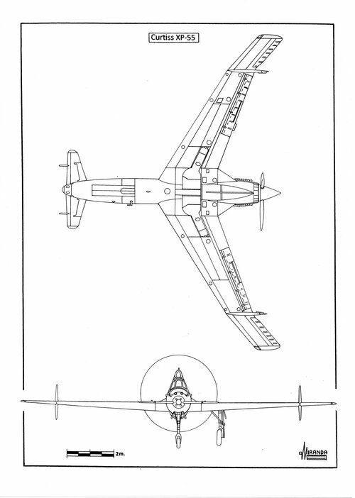
On 10 July 1942 the USAAF ordered three prototypes, the 42-78845 flew on 13 July 1943 powered by one 1,425 Allison V-1710-95, V-12, liquid-cooled engine, with mechanical supercharger, driving a three-bladed (jettisonable) pusher airscrew.
The aircraft was fitted with laminar-flow swept wings angled back 45 degrees and tricycle undercarriage.
USAAF was unimpressed with the 377 mph top speed reached with the Allison engine versus the 507 mph promised with the X-1800 cancelled in October 1940.
The first prototype showed excessive take off run, dangerous stall behaviour, poor longitudinal stability, low-speed handling problems and engine overheating.
On 15 November 1943 the plane was lost, in an inverted spin, when the engine failed.
The second prototype 42-78846 flew on 9 January 1944 suffering from ‘no-warning before stalling’ phenomena. To improve the stall characteristics the nose elevator and the aileron tabs were modified.
The third prototype 42-78847 was flown on 25 April 1944, fitted with wing extensions and modified nose elevator and armed with four 0.50 cal nose mounted machine guns.
On 27 May 1945 the aircraft crashed when the pilot attempted a barrel roll.
Americans were not lucky with the Curtiss XP-55, after four years of flight testing they have not achieved an airplane sufficiently stable to take part in combat operations.
Although it was less sensible to the compressibility buffeting than conventional airplanes, thanks to a NACA 0015 type wing profile, it was also too heavy and slower than the P-47 and P-51 in service.
Curtiss XP-55 technical data
Power plant: one 1,425 hp Allison V-1710-95, V-12, liquid-cooled engine, with mechanical supercharger, driving a three-bladed (jettisonable) pusher airscrew.
Wingspan: 44.5 ft (13.56 m), length: 29.6 ft (9.02 m), height: 10 ft (3.05 m), wing area: 235 sq. ft (21.83 sq. m), max speed: 390 mph (630 kph), max weight: 7,330 lbs (3,324 kg), service ceiling: 34,600 ft (10,550 m), armament: six 0.50 cal M2 heavy machine guns.
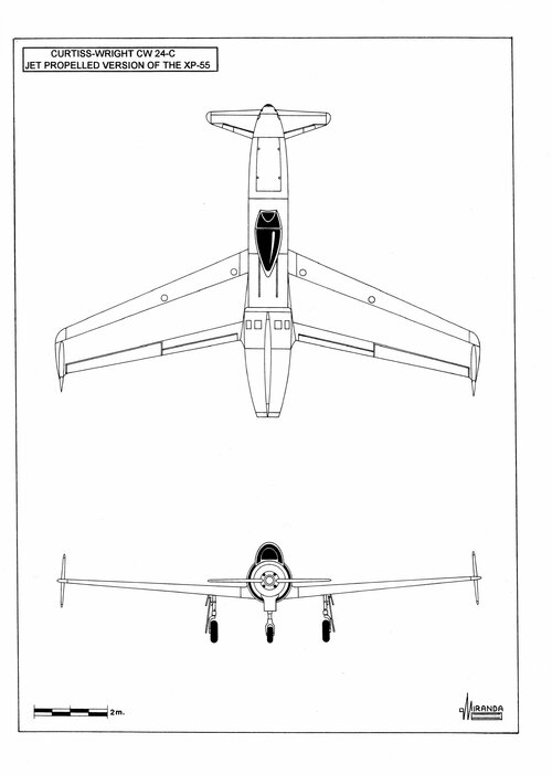
Before cancelling the project, the Curtiss firm proposed the production of a jet version based on the original P 249-C project, known in the specialized literature as P 286-17 or CW 24-C. It would have been propelled by a centrifugal De Havilland H-1B Goblin turbojet with a fuel tank of 1,059 lt., located behind the pilot, and armed with four 0.50 cal M2 machine guns. Its mass production was abandoned in favor of the Lockheed P-80.
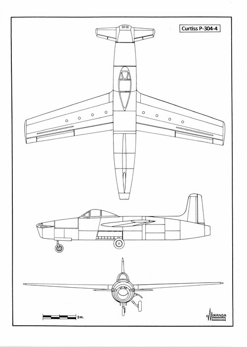
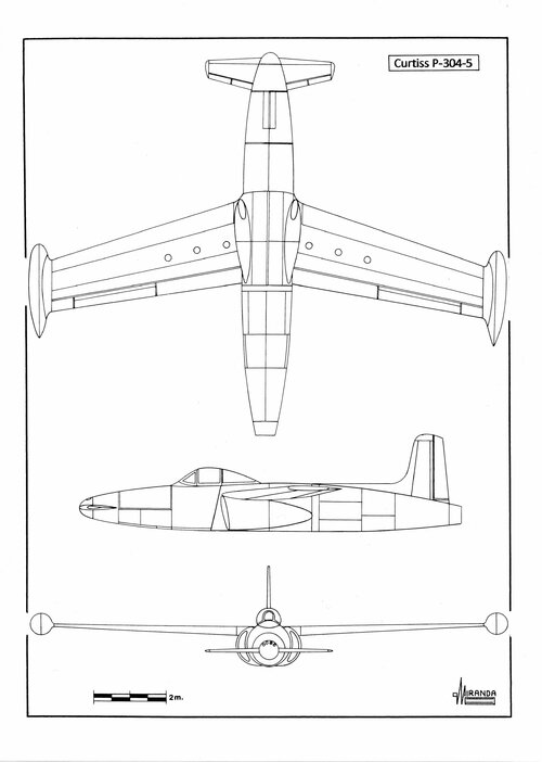
On 31 March 1945 Curtiss proposed two versions of the P-304 a single-jet, medium-range fighter specifically designed to overcome the effects of compressibility, using the accumulated knowledge from the XP-55 programme.
Curtiss CW 24-C technical data
Power plant: de Havilland H-1B Goblin turbojet with 2,460 lbs (1,114 kgf) static thrust.
Wingspan: 39.36 ft (12 m), length: 28.10 ft (8.57 m), height: 9 ft (2.74 m), armament: four 0.50 cal M2 heavy machine guns.
Curtiss P-304-4 technical data
Power plant: one General Electric TG-180 turbojet with 4,000 lbs (1,814 kgf) static thrust.
Wingspan: 40 ft (12.2 m), length: 33.8 ft (10.3 m), height: 9.5 ft (2.9 m), wing area: 240 sq. ft (21.6 sq. m), max weight: 14,470 lbs (6,564 kg), armament: four 0.50 cal M2 heavy machine guns.
Curtiss P-304-5 technical data
Power plant: one General Electric TG-180 turbojet with 4,000 lbs (1,814 kgf) static thrust.
Wingspan: 40 ft (12.2 m), length: 33.4 ft (10.21 m), height: 9.5 ft (2.9 m), wing area: 240 sq. ft (21.6 sq .m), estimated max speed: 622 mph (1,001 kph) at 10,000 ft, estimated climb rate: 5,530 ft/min, max weight: 14,170 lbs (6,428 kg), combat radius: 500 miles (805 km), armament: four 0.50 cal M2 heavy machine guns.
Attachments
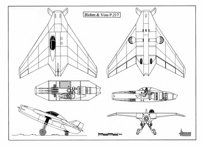
Blohm und Voss P.217 (February 5, 1945)
The ingenious ‘bat wing’ configuration used in the fighter projects of the firm since July 1944 was too advanced for its time and the Luftwaffe technicians criticised the lateral stability of the designs.
One of the main objections to the ‘bat wing’ configuration was its high wing loading that required large take-off strips at a time when fighters were forced to use tranches of autobahns.
The P.217, a conservative version with delta wing, was presented as an alternative.
So the P.217 was designed with a great surface wing, similar to the one in the Arado E 581, with forward swept canard winglets to improve take-off, performance and low speed control.
To avoid power losing in the turbojet, the air duct was completely straight and free of obstacles, having to place the cockpit in an asymmetric position.
Non-strategic materials and some already existent mechanical components, like a Bf 109 G-6 undercarriage, were proposed for its building.
Visibility during take-off and landing was practically non-existent so one might speculate on the possibility of some ventral window to help on these manoeuvres.
Blohm und Voss P.217 technical data
Wings: built of wood/plywood, aspect ratio 2.46:1, 65/57-degrees swept at the leading edge, -60/27-degrees at the trailing edge and 15-degrees anhedral wingtips, housing elevators, ailerons and flaps. Fuselage: built of steel and light alloy, housing the armament, the undercarriage, the cockpit, a fuel tank, the turbojet, the tailfin (built of wood) and the 45-degrees forward swept winglets. Engine: one HeS 011A-1 turbojet rated at 1,300 kg static thrust. Armament: three MK 108/30 cannons in the nose. Undercarriage: from a Bf 109 G-6 standard. Wingspan: 8 m. Length: 7.05 m. Height: 3.09 m. Wing area: 26 sq. m. Max weight: 4,200 kg.
Attachments
HereHas any canard wing craft have fore and aft props and flaps on front and back of the wings?
Two pilots with backs towards one another...so you could take off and land in either direction?
Attachments
Similar threads
-
-
-
-
 Thunderbolt & Lightning -- The History of Aeronautical Namesakes
- Started by saturncanuck
- Replies: 1
-
