- Joined
- 27 December 2005
- Messages
- 17,664
- Reaction score
- 25,693
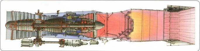
I've always wondered about how the Perm D-30F6 turbofan is able to power the MiG-31 to Mach 2.83, when it appeared to be a relatively conventional adaptation of the D-30 commercial turbofan family.
Source is ENGINES OF RUSSIAN COMBAT AIRCRAFT by Kotelnikov V. R., Khrobystova O. V., Zrelov V. A., Ponomarev V. A. (Mediarost, 2020)
Heat exchanger is shown below:

A somewhat different heat exchanger for turbine cooling air was fitted on the AL-31F

but it appears to be intended to reduce specific fuel consumption rather than increase high speed thrust. This might explain the disparity in SFC between AL-31F and RD-33, which are otherwise fairly similar technically.
As a side note the «огневой дорожки» 'fire track" method of igniting the afterburner was also used on the RD-33, where it was a contributing factor to low TBO and limited engine life as outlined in https://www.sciencedirect.com/science/article/pii/S1350630722000620. The AL-31F used a similar system.
Essentially rather than having separate igniter plugs in the afterburner, the afterburner is lit by a secondary pilot jet nozzle flame which travels through the turbine blades and mixer to the afterburner section.
The advantage of this ignition mix is very reliable afterburner operation, at higher speeds and altitudes in particular.
The disadvantage is the stators in the flame path get extra wear from the flame when afterburners are lit, as do the turbine blades to a lesser degree because they are rotating through it.

Other than the cooling boost from the heat exchanger allowing the engine to run hotter at high speed and temperature, the only other "secret" to high speed performance was careful attention to the air intake and exhaust, which are very important in high speed flight.
Source is ENGINES OF RUSSIAN COMBAT AIRCRAFT by Kotelnikov V. R., Khrobystova O. V., Zrelov V. A., Ponomarev V. A. (Mediarost, 2020)
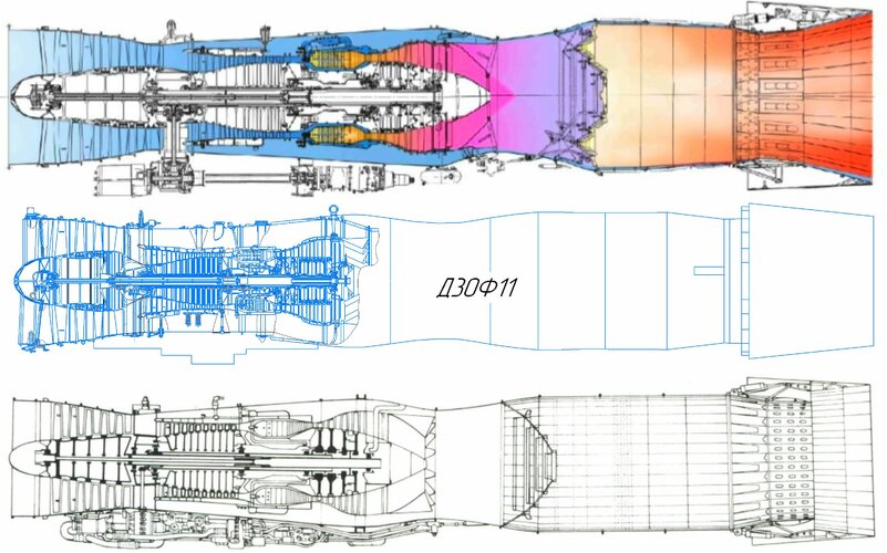
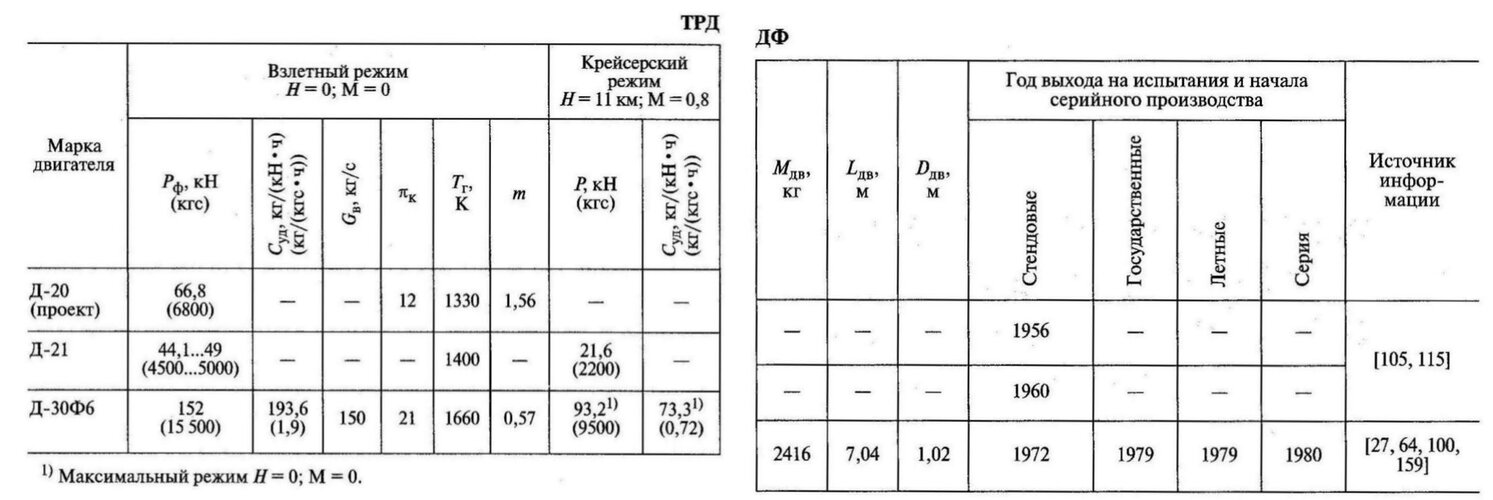
So, essentially its a conventional low bypass ratio turbofan, with improved cooling of the high pressure turbine using a heat exchanger to cool the bleed air taken from the high pressure compressor in the bypass air flow so it is cooler when it arrives at the HP turbine. This allows the turbine entry temperature to increase from the sea level maximum when flying at high speeds and altitude.The D-30 was the first experimental domestic turbofan engine with a mixing-type afterburner, which was designated D-30F (product "38"). It was developed and tested in 1965-1969. The aerodynamic appearance of the compressor remained the same as that of the civil prototype, only the materials in the turbocompressor section were replaced. In order to significantly increase the thrust, it was necessary to significantly increase the gas temperature in front of the turbine. The engine developed 11,500 kgf in afterburner. But this was not enough - a thrust of 15,500 kgf was required. The creation of such an engine was associated with high technical risks associated with the general insufficient level of theoretical and practical knowledge on the use of turbofan engines on a supersonic aircraft.
"It was unknown whether the engine compressor, "used" to work with a subsonic unshaded air intake, would retain its functionality when it interacted with a supersonic inlet... - writes V. G. Avgustinovich. - Would the turbine withstand the increased gas temperature, provided that the cooling air temperature reached 700 ° C." According to Valery Grigorievich, the OKB-19 designers had to disprove several theoretical dogmas that scientists at that time considered unshakable. One of them stated that the maximum gas temperature in front of the turbine should be maintained starting from takeoff mode near the ground. But it was not possible to obtain frontal thrust at a speed of 3000 km / h, which was specified in the technical specifications for the aircraft.
The necessary solution had already been tested on the RD36-41 single-shaft turbojet engine with afterburner. To obtain the required thrust at an altitude of 20 km and a speed of 3,200 km/h, the Rybinsk designers had to increase the gas temperature in this mode by 75° compared to takeoff. This was not enough for the turbofan engine. It was necessary to add 150° to the gas temperature in the takeoff mode. For the demonstration version of the future D-30F6, a program was developed to increase the gas temperature in front of the turbine with an increase in the flight speed of the aircraft, which later became known as "temperature spin-up". Thanks to it, the required thrust was provided at an altitude of 20 km at a speed of 2,500 km/h. Now the dogma has been refuted for dual-circuit engines with afterburner as well.
However, the TsIAM scientists still considered the creation of a bypass engine with afterburner with such high parameters for such high flight speeds to be impossible in principle. They wrote about this in the official negative conclusion on the project. But in spite of everything, the general designer of the Mikoyan Design Bureau R. A. Belyakov decided to take a risk and accepted P. A. Solovyov's offer. According to Pavel Aleksandrovich's memoirs, "we were still terribly afraid. For example, meetings with Ustinov [the secretary of the CPSU Central Committee responsible for defense. - Author's note] began with a discussion - is it possible to make such an engine?
They did not believe it. All the time they raised one question, then another... But Batitsky [the commander-in-chief of the Air Defense. - Author's note] auth.] was pushing hard, and Ustinov, apparently, wanted to have such a machine. And he announced there that we would make this engine. And Tumansky's engine was put aside." In the fall of 1971, bench tests of the D-30F6 prototype began. On September 16, 1975, the E-155MP aircraft with two D-30F6s made its first flight (test pilot A. V. Fedotov). During the flight research period, two aircraft were lost - the first prototype and the first production one. There were no casualties, and this, in comparison with the results of other machines being created, was quite a good indicator. However, both incidents were due to the fault of the engines. During eight years of testing, starting with the first bench test, the D-30F6 was deeply fine-tuned, its units were adapted to real operating conditions (35 prototypes were used).
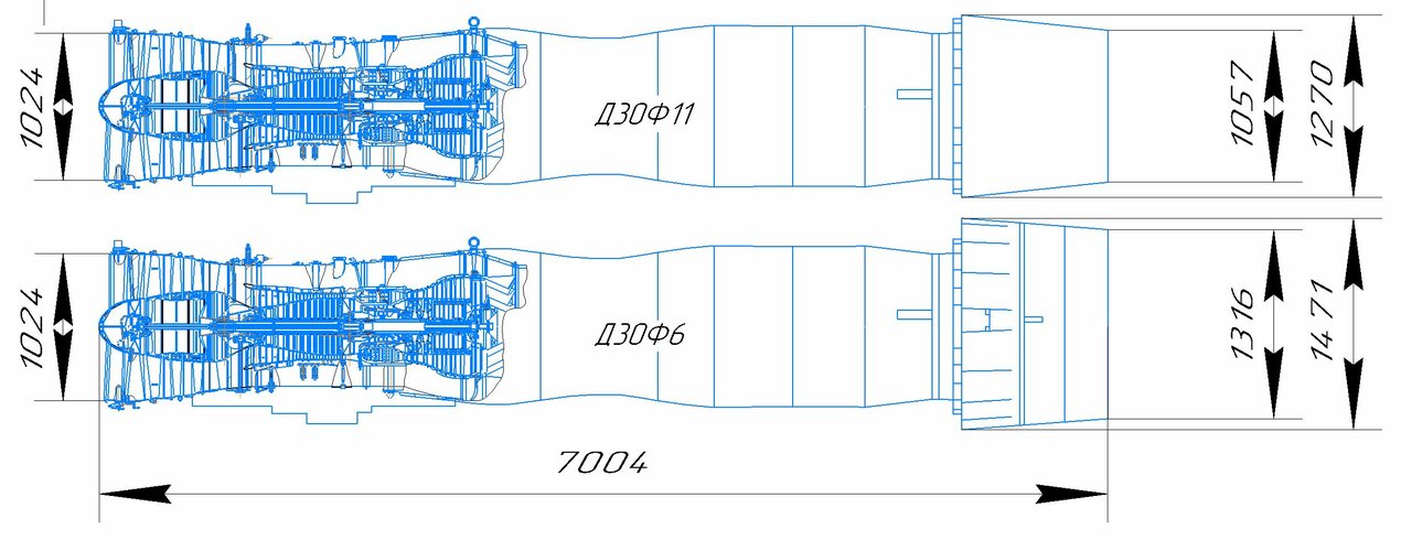
As a result, the dimensions determined back in 1969 were preserved, but many things underwent changes. First of all, the materials: the engine was now completely made only of titanium and nickel. Much effort was put into improving the afterburner, its mixer and the front device, so that improve the ignition system and increase the stability of the combustion process in high-altitude conditions. In 1977, the Perm Engine Plant began serial production of the D-30F6, and two years later it passed state tests.
The D-30F6 engine has a modular design that improves manufacturability and maintainability. The low-pressure compressor consists of five stages and has a total pressure increase ratio of 3, the high-pressure compressor is 10-stage with a total pressure increase ratio of 7.05 (at the design point - 8). The inlet guide vane of the HPC is rotary.
The peripheral speed at the tips of the working blades of the first impeller is 325 m/s.
The rotor of the high-pressure compressor is of a disk type with reinforcement of the last stages. The compressors are relatively low-pressure, which made it possible to obtain the required stability margin. The combustion chamber is a straight-through tubular-annular one, with 12 fire tubes.
The high-pressure turbine is a cooled two-stage one. Air for cooling the nozzle and working blades of both stages is taken after the fifth and last stages of the high-pressure compressor. An air-to-air heat exchanger was installed to reduce the temperature of the cooling air. This technical solution was brought to series production for the first time in the world. To reduce the temperature of the main disks and blades, cover deflectors are attached to the disks.
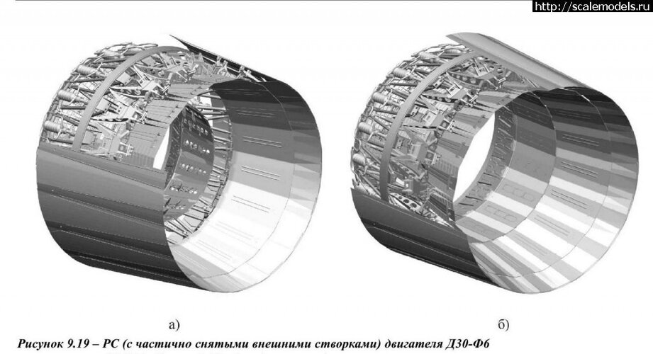
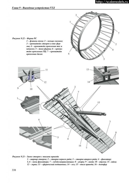
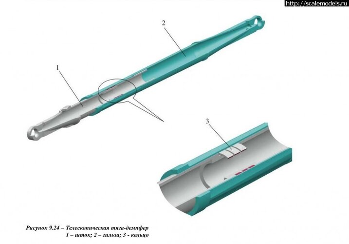
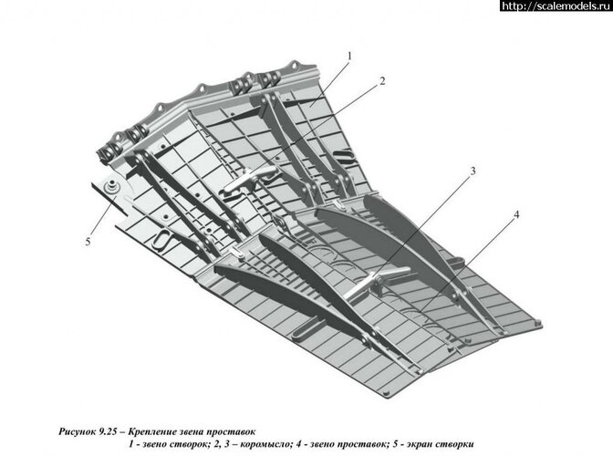
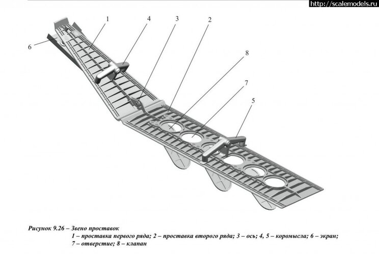
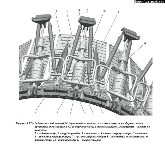
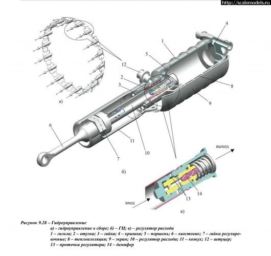
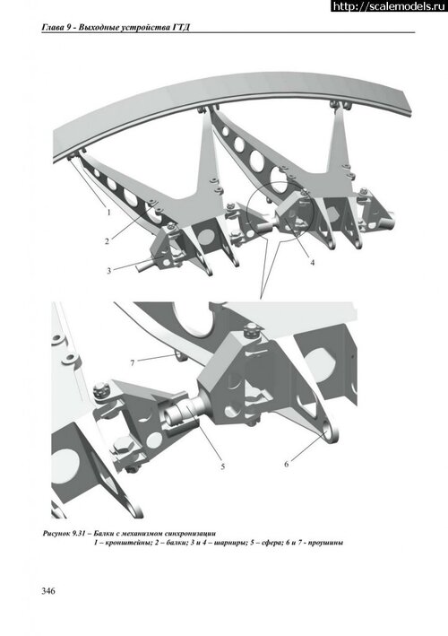
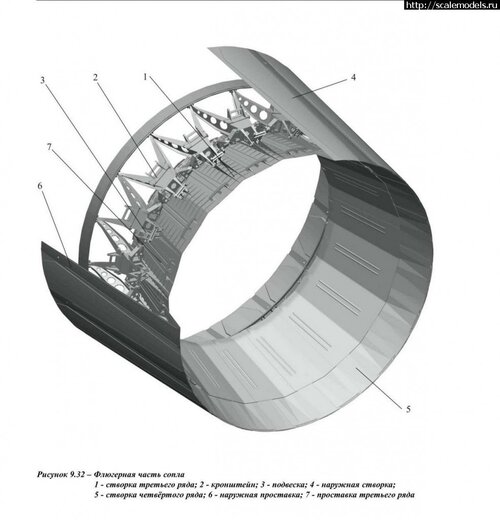
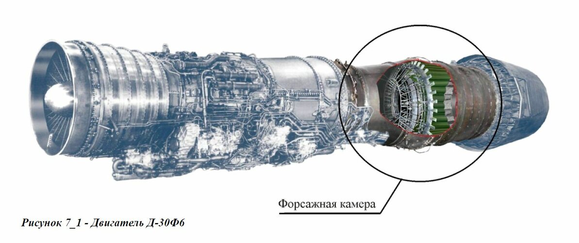
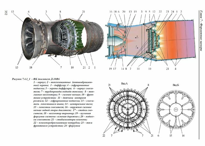
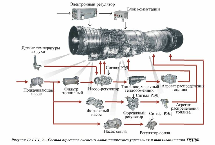
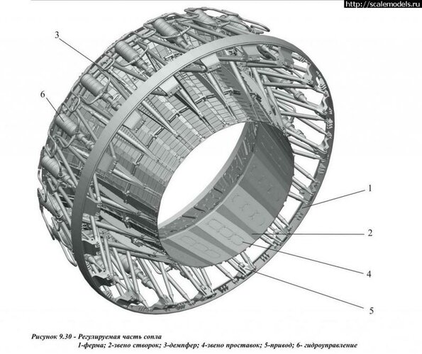
Two intermediate disks with labyrinth seals are installed between the main disks. The low-pressure turbine is a two-stage uncooled one. For the first time in a domestic serial engine, a mixing-type afterburner and an adjustable all-mode nozzle of a flap design are used, the subsonic part of which is controlled autonomously forcibly , and the supersonic part is aerodynamically. An interesting feature of the nozzle design are the holes made on the second-row spacers, closed from the flow-through side by hinged valves. The holes with valves ensure the suppression of harmful gas oscillations in off-design modes. The critical cross-sectional area of the nozzle changes depending on the engine operating mode by turning the first and second row flaps using 18 hydraulic cylinders. The afterburner with four annular flame stabilizers is ignited by the "fire track" method. This system was previously implemented on the experimental turbojet engine RD-36-41 of the Rybinsk OKB-36.
Heat exchanger is shown below:

A somewhat different heat exchanger for turbine cooling air was fitted on the AL-31F

but it appears to be intended to reduce specific fuel consumption rather than increase high speed thrust. This might explain the disparity in SFC between AL-31F and RD-33, which are otherwise fairly similar technically.
As a side note the «огневой дорожки» 'fire track" method of igniting the afterburner was also used on the RD-33, where it was a contributing factor to low TBO and limited engine life as outlined in https://www.sciencedirect.com/science/article/pii/S1350630722000620. The AL-31F used a similar system.
Essentially rather than having separate igniter plugs in the afterburner, the afterburner is lit by a secondary pilot jet nozzle flame which travels through the turbine blades and mixer to the afterburner section.
The advantage of this ignition mix is very reliable afterburner operation, at higher speeds and altitudes in particular.
The disadvantage is the stators in the flame path get extra wear from the flame when afterburners are lit, as do the turbine blades to a lesser degree because they are rotating through it.

Other than the cooling boost from the heat exchanger allowing the engine to run hotter at high speed and temperature, the only other "secret" to high speed performance was careful attention to the air intake and exhaust, which are very important in high speed flight.
Last edited: