Rotary recovery of spent booster stages

Antonio

Moderator
Staff member
Senior Member
Joined
22 January 2006
Messages
4,114
Reaction score
1,695
While waiting for Orionblamblam posts I'd like to post this beast from Hiller
(Vertical Challenge. The Hiller Aircraft Story from Jay P. Spenser. ISBN 0-295-97203-3)

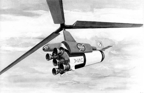
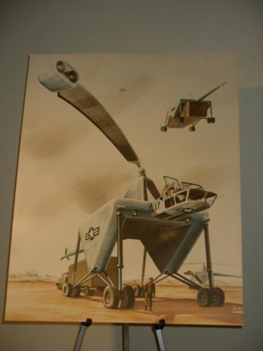
Formally proposed in 1965, it was designed to retrieve spent 200 ton Saturn V booster first stages. This tip-jet powered helo had a rotor 300 feet in diameter. Gross weight of one million pounds.

more from Stargazer2006

Finally, some light on the Hiller/NASA crane designed to recover Saturn V boosters (Model number unknown):

Company hopes for giant tip-powered helicopters revived briefly in 1965 when the National Aeronautics and Space Administration considered sponsoring a Hiller flying crane to recover Saturn V moon booster first stages during Project Apollo. Aerial recovery of this spent first stage, which weighed up to 400 tons, dictated that the Hiller/NASA recovery vehicle be the largest aircraft of any kind yet proposed. The resulting design featured a gross weight of about a 450t and a rotor more than 100m in diameter. Powered by two or more jet engines per blade, this rotor would have turned at 60 rpm, presenting the illusion of slow motion to observers below.

As laid out, the Hiller/NASA flying crane would loiter at 3000m some 750km downrange from Cape Kennedy. Sighting the moon booster descending by parachute, it would use special recovery gear to snag the spent rocket and winch it securely in. If the first pass was unsuccessful, sufficient time would remain for two more attempts before the booster was too near the ocean's surface for another try.

Expensive as such a helicopter would have been, the huge aircraft would have paid for itself with the first several recoveries. But long-range planning for the nation's space program was beginning to favor the concept of a reusable space shuttle over single-use rockets, and this recovery helicopter was not funded.

An artist's view of the Hiller/NASA crane proposal.
 

Attachments

  • Hiller NASA recovery vehicle.jpg
    Hiller NASA recovery vehicle.jpg
    139 KB · Views: 648
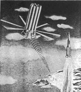
Well, looking for something else in AW&ST, found this. Hiller proposed the same almost five years later.This was from Bell. The system was predicted at being approx 10 per cent the empty weight of the stage or 1/2 per cent of the entire vehicle. The rotor was intended for Saturn-Nova class vehicles (it was 1960) and kept folded until 200.000 ft and Mach 3. Control systems allowed (Bell said) to precisely land the stage from 25.000 ft altitude with a deviation of a hundred feet. From AW, April 18 1960 page 115.
 

Attachments

  • Bell_saturn.gif
    Bell_saturn.gif
    122.2 KB · Views: 369
Mmmm, the rotors at the bottom of the assembly....
Yummy stability control issues in perspective!
 
Don't know the weight distribution in an empty stage.... suspect the rotor was at C.O.G.
 
It reminds the ROTON X-prize project.

Markus Lindroos website also have a "rotor landing" small shuttle...(I've to check!)
 
I found new data to that Hiller Proposal
http://www.thespacereview.com/article/1045/1

they wanted to recover a spend Saturn V S-IC Stage in the air :eek:

The plan was for the helicopter to be capable of loitering in the recovery area for up to six hours, flying at an altitude of 4,500–6,000 meters (15,000–20,000 feet).

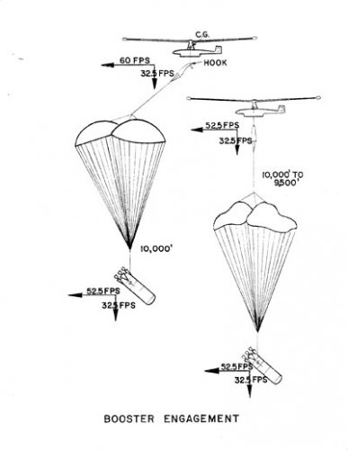
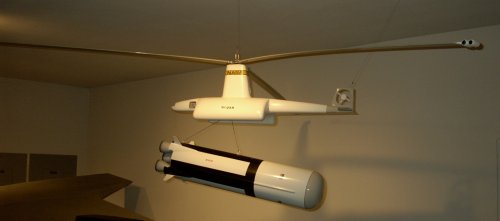
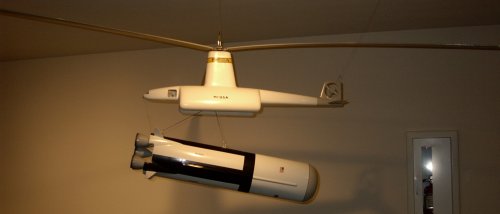
Upon sighting the booster, the helicopter would head for it and intercept it at approximately 3,000 meters (10,000 feet). The S-1C’s parachute system would be descending along a glide path with more forward than downward velocity. The helicopter would align with the glide path and approach from behind and above, descending to match trajectories with the booster. It would snag the pickup chute with a grappling hook suspended from the helicopter’s center of gravity and gradually assume the weight of the booster. The parachutes would be deflated and the booster suspended about 215 meters (700 feet) below the helicopter.

The helicopter would then reel-in the booster, rotating it to a horizontal position and snugging it up underneath the helicopter—and then returning it to the launch area or some other destination on land. Of course, the S-1C stage would fall over 650 kilometers (350 nautical miles) from the launch site. How feasible was it for the world’s largest helicopter, carrying the world’s largest rocket, to fly this distance back home? What about wind? Although Hiller’s proposal did not say so, a far better solution would have been for the helicopter to set the stage down on a ship near the recovery area. Of course, it would have to be a big ship, like an aircraft carrier, or a barge. But nothing would be small with this concept.

index.php
 

Attachments

  • 1045a.jpg
    1045a.jpg
    12.4 KB · Views: 226
  • 1045b.jpg
    1045b.jpg
    25 KB · Views: 203
  • 1045c.jpg
    1045c.jpg
    22.8 KB · Views: 207
Great find Michel, although I think is more an evolution of the original idea. It is 5 years later that the AW&ST one, and clearly different (and more complex).
 
i am just trying to imagne the sound of that wee beasty ... :cool:

the whop whop of the rotor would probably break windows at 15 miles distance
 
Commenting on the idea of Rotors on the booster rather than a recovery-helicopter;

I'm a bit confused. The illustration actually DOES show the rotors being placed just above the engines which would put the majority of the "mass" below the rotor since the engine assemblies, thrust structure, etc, mass much more than empty propellant tanks. All well and good since I've seen dozens of concepts that put the major mass below the rotors UNLESS the rotors are "powered" in some form or fashion. Everything I've read says that rotors ABOVE the mass are inherently unstable while rotors mounted BELOW the mass are actually stable needing less active control. While counter-intuative the various research work done for the Hiller and other flying platforms confirmed the theory and provided a lot of hard data on such configurations.

As long as the rotor is being used as a "drag" device with limited or no need for active flight abilities it would seem that mounting the rotors ABOVE the CG is advisable, while if you actually need to "fly" beyond a limited amount mounting the rotor BELOW the CG is more stable and practical.
In the original "ROTON" design with the rotors providing a large amount of thrust early on in the flight and the need for positive flight control the rotors were mounted low down on the hull, while later as they were reduced to "just" providing braking and landing thrust they moved higher up the design. So in essence the major reason the ROTON Test Vehicle was 'unstable-and-difficult-to-fly' was inherent in the design itself since with the rotors where they were the design was constricted to using them ONLY for drag and landing and the very idea of "test-flights" was out of whack with the design! Similarly there was a concept to put folding, extensible rotors on the Crew Exploration Vehicle (CEV) for recovery and landing. No "power" was provided for though it was noted that "small-H2O2" rockets could help extend the landing control, but it was noted that "flying" the design any significant distance was problematical "due to the unstable nature" of the top mounted rotors.

So my confusion stems I suppose from the fact that there are two KNOWN ways to design a "rotor" vehicle for recovery and/or flight purposes and both communities KNOW about the other. But there seems to be a rather dismissive attitude that says any "rotor" system MUST be mounted "above" the majority of the vehicle mass even if aerodynamics pretty much PROVES this is not true.

Rotor recovery would seem to give a LOT of advantages for booster (and spacecraft in general) recovery yet it seems ignored mostly because of a perceived "need" to put the rotor as high as possible on the vehicle.

Why is that?

Randy
 
What you are saying make sense but the AW article doesn't give any details on mass distribution of the booster intended for recovery (it is not a "real" booster, it is a NOVA-like cluster stage concept, maybe even an actual design, in 1960 a dozen companies were working on that, under contract or not) so it is impossible to locate the CG position (mine is a guess). All in all, I suspect that since these rotors are more "guiding rotary brake" than conventional rotors, but work much like the rotor of an helicoper landing in autorotation in emergency (engine-off) situations, someone is compelled to put them were the rotor in an helicopter is, on top. The parachute analogy is strong, too. Maybe Bell knew better. Actually, the AW article refers to a conference paper giving much more details. I planned to track it down back then but I overlooked it. Let me see what I'm able to do.
 
Skybolt said:
What you are saying make sense but the AW article doesn't give any details on mass distribution of the booster intended for recovery (it is not a "real" booster, it is a NOVA-like cluster stage concept, maybe even an actual design, in 1960 a dozen companies were working on that, under contract or not) so it is impossible to locate the CG position (mine is a guess). All in all, I suspect that since these rotors are more "guiding rotary brake" than conventional rotors, but work much like the rotor of an helicoper landing in autorotation in emergency (engine-off) situations, someone is compelled to put them were the rotor in an helicopter is, on top. The parachute analogy is strong, too. Maybe Bell knew better. Actually, the AW article refers to a conference paper giving much more details. I planned to track it down back then but I overlooked it. Let me see what I'm able to do.
"Generally" (note the quotes, I don't claim to be an expert.... unless I think I can get away with it ;) ) in large boosters such as the Saturn/Nova, etc, once your propellant is used up the CG shifts WAY aft towards the engines and thrust-structure because everything forward of that is just empty propellant tanks. YMMV, but I'm only "guessing" also and without any "specs" on the booster that's pretty much all we CAN do :)

Please let me know what you find, also I have a bunch (on one hard drive or another) of the rotor recovery papers from NASA that Rotary Rocket was citing for the ROTON concept. Let me know what the paper number is and I'll see if I have it.

Randy
 
The rotors would have been 400 feet in diameter, the beast's empty weight would have been over 450,000 pounds, and its gross weight would have been about 1,000,000 pounds. Talk about whop-whop-whop! The idea was that it would descend after loiteri9ng for as much as 6 hours from an altitude of 15-20,000 feet, snag the booster's parachutes in mid-air, and bring the spent booster home dangling some 700 feet below.
Any volunteers to fly it?
 
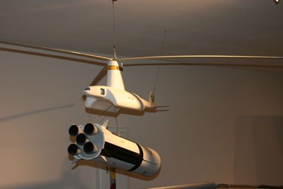
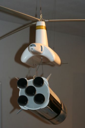
Video of Hiller Rotary Wing System for Booster Recovery or "Air Tug" at Hiller Aviation Museum and Institute.

Hiller's concept for world largest Air Tug Helicopter designed to capture the parachute of a descending rocket.


View: http://www.youtube.com/watch?v=TlZuskXJyiE
Hiller Aviation Museum said:
The Hiller Air Tug
Here are a series of videos that are mainly played in our gallery alongside exhibits, but we wanted patrons unable to visit the museum on a regular basis the chance to access them at a moment's notice. Enjoy!
Video:
View: https://youtu.be/MHaxySnEPTc

Code:
https://youtu.be/MHaxySnEPTc
 
A cluster tank design with its own tip-jets and perhaps lighter landing gear-or boost-back with heavy gear due to hover-slams...with Falcon using more kerosene for that-with LOX than tip-jets: a wash?
 

Similar threads

Please donate to support the forum.

Back
Top Bottom