You are using an out of date browser. It may not display this or other websites correctly.
You should upgrade or use an alternative browser.
You should upgrade or use an alternative browser.
Rheintochter anti-aircraft rockets
- Thread starter Barrington Bond
- Start date
- Joined
- 29 September 2006
- Messages
- 1,700
- Reaction score
- 1,182
Barrington Bond said:Anyone know what the item is on the small grey trolley?!
Regards,
Barry
Well, the end nearest the camera has handles machined into the skirt - much like a gas cylinder. Might be part of a rocket pressurisation system.
Starviking
- Joined
- 26 January 2011
- Messages
- 2,228
- Reaction score
- 601
As it appears to be posed amongst various German WWII missiles, and it does look faintly familar, I suspect it is part of the V-1 launching system. It might be part of the Hydrogen-Peroxide steam launcher?
Grzesio
ACCESS: Secret
Hello all, my first post here. 
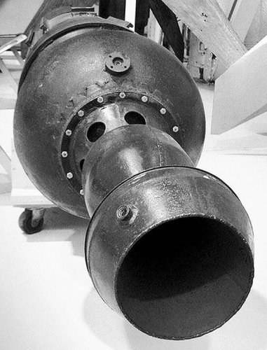
The small object is a mid fuselage section of the Rheintochter R III F antiaircraft rocket - basically a tubular tank section with wing sockets, then a spherical compressed air tank for pressurizing the propellants tanks and the combustion chamber. It's - most probably - the Konrad engine.
A seedy (with misplaced canards) and simplified representation of the real thing can be seen here:
http://www.net.bialystok.pl/~hess/r_ppk_rheinmetall_borsig_rheintochter_r3.htm
Regards
Grzesio
Grzesio
ACCESS: Secret
No. 
This second missile is an earlier version, the Rheintochter R I with two solid fuelled stages - a subsonic bird of not too impressive performance.
The R III was a late war supersonic development (very few were built and flown, probably none of them fully functional). Its first stage comprised of two solid fuelled engines mounted on sides of the 2nd stage, rather than behind it. The 2nd stage was to be equipped with Rheinmetall or Konrad liquid fuelled engine (version R III F) or an enlarged solid fuelled engine (R III P).
Regards
Grzesio
- Joined
- 25 June 2009
- Messages
- 14,141
- Reaction score
- 4,332
RHEINTOCHTER
This missile is an antiaircraft rocket developed by Rheinmetall-Borsig, one of three similar developments sponsored by Halder of GL Flak E5, the others being Wasserfall and Enzian.
The first experiments with steering were made in February, 1944. According to one report Rheintochter was abandoned in favor of Hs-117 after a demonstration to Goering and Speer at Karlshagen in October, 1944. On 6 February 1945, SS leader Kammler stated that Rheintochter was to be closed out at once.
Rheintochter had a diameter of 53.6 cm, a length of 500 cm, a starting weight of 1570 kg, final weight of 685 kg, with a pay load of 160 kg of explosive. Its maximum speed was 410 m/sec, maximum height 15.2 km, range 18.9 km. It was launched with powder rockets. On 22 January 1945, 82 tests had been made, 39 without control, 21 with preset program of control, and 22 with radio control. Fifty-six functioned satisfactorily.
Source: Technical Intelligence Supplement, May 1946
- Joined
- 25 June 2009
- Messages
- 14,141
- Reaction score
- 4,332
Rheintochter I photos from Guidance and Homing of Missiles and Pilotless Aircraft, May 1946:
Attachments
Grzesio
ACCESS: Secret
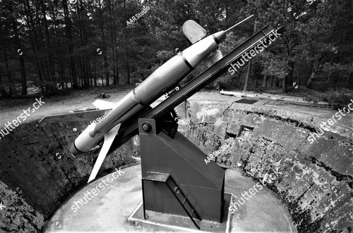
A mock-up in Leba...  The concrete foundation is original, though.
- Joined
- 9 October 2009
- Messages
- 21,147
- Reaction score
- 12,249
Thought it was something like that.
pathology_doc
ACCESS: Top Secret
- Joined
- 6 June 2008
- Messages
- 1,561
- Reaction score
- 1,415
Back after a long break.
I love these piston-era and early-jet-era missiles. They don't age well, but they're almost instantly date-able by the wing, fin and body planforms as first-gen and you have to feel for the designers operating at or beyond the ragged edge of then-current knowledge.
I love these piston-era and early-jet-era missiles. They don't age well, but they're almost instantly date-able by the wing, fin and body planforms as first-gen and you have to feel for the designers operating at or beyond the ragged edge of then-current knowledge.
Johnbr
ACCESS: Top Secret
- Joined
- 6 May 2007
- Messages
- 753
- Reaction score
- 312
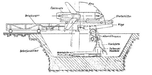
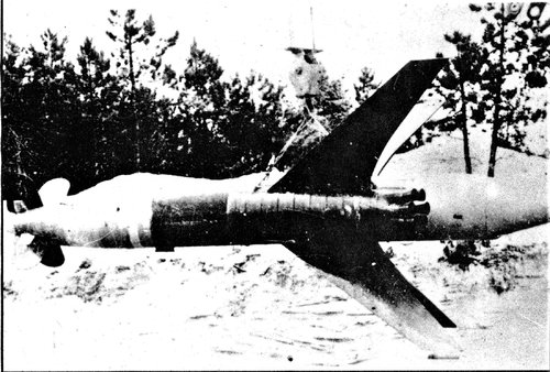
Rheintochter R III
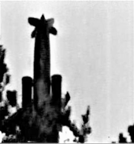
The R-3 version of the missile was designed to achieve the 10-12 km altitude requirement. Work had begun in May 1944, and six launches of the prototype were made in January 1945. There were two variants: the R-3F version with a Konrad engine (Nitric acid/Tonka-250 or Nitric acid/Visol) in the cruise stage; and the R-3R with a solid propellant cruise engine. In both versions parallel booster motors were used in place of the in-line first stage of the R-1. The R-3 had a length of 4.75 m, and an 1170 kg launch mass. The boost motors provided 1400 kgf for 0.9 seconds. Altitude was to be 12 km at a range of 20 to 25 km. However the missile never reached the stage of state trials testing. Peenemuende was abandoned on 20 February 1945, by which time only 15 R-3's had been completed. The solid rocket motor for the R-3R had reached the stage of stand tests on 6 February 1945, but further work was cancelled.


The R-3 version of the missile was designed to achieve the 10-12 km altitude requirement. Work had begun in May 1944, and six launches of the prototype were made in January 1945. There were two variants: the R-3F version with a Konrad engine (Nitric acid/Tonka-250 or Nitric acid/Visol) in the cruise stage; and the R-3R with a solid propellant cruise engine. In both versions parallel booster motors were used in place of the in-line first stage of the R-1. The R-3 had a length of 4.75 m, and an 1170 kg launch mass. The boost motors provided 1400 kgf for 0.9 seconds. Altitude was to be 12 km at a range of 20 to 25 km. However the missile never reached the stage of state trials testing. Peenemuende was abandoned on 20 February 1945, by which time only 15 R-3's had been completed. The solid rocket motor for the R-3R had reached the stage of stand tests on 6 February 1945, but further work was cancelled.
Johnbr
ACCESS: Top Secret
- Joined
- 6 May 2007
- Messages
- 753
- Reaction score
- 312
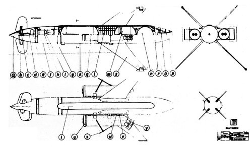
Schemes of anti-aircraft missiles of the Reintochter series R-3:
1 - distance sensor with heat-resistant fairing; 2 - steering wheels (two pairs); 3 - rudder shafts with bearings; 4 - mechanical steering machines; 5 - electric motor steering gear; 6 - "middle building" with electrical equipment; 7 - elastic suspension frame of a gyroscope; 8 - a gyroscope; 9 - receiver and battery; 10 - oxidizer tank - Salbai; 11 - rotary intake of the oxidizer; 12 - warhead with ready-to-use striking elements; 13 - a tank with fuel - Vizol; 14 - ball balloon with compressed air; 15 - a combustion chamber with a nozzle; 16 - tail fairing made of tin; 17 - pressure reducing valve for testing the engine thrust change program; 18 - rotary fuel intake; 19 - wings of glued wood; 20 - tracer; 21 - cable channel; 22 - emphasis for the accelerator; 23 - pyrobolt accelerator; 24 - jet nozzles of the accelerator (axes pass through the central heating unit); 25 - removable accelerator cover with igniter; 26 - air brake; 27 - yoke for mounting a rocket on a launcher; 28 - igniter; 29 - charge of solid fuel; 30 - grate; 31 - starting accelerator
The accelerator consisted of a steel case with a diameter of 320 mm and a 7 mm wall. At the ends, it was closed with removable covers - flat - in front and spherical - in the back. The starting accelerator weighing 390 kg contained 170 kg of diglycol gunpowder. Within 0.9 s, he developed a thrust of the order of 143 kN (1450 kgf). Each accelerator had seven nozzles inclined to the longitudinal axis, the thrust vector of which passed through the center of gravity of the rocket. This simplified rocket balancing with different thrust accelerators. Reliable and synchronous separation of accelerators was carried out by pyro-bolts and aerodynamic brakes in the form of duralumin plates.
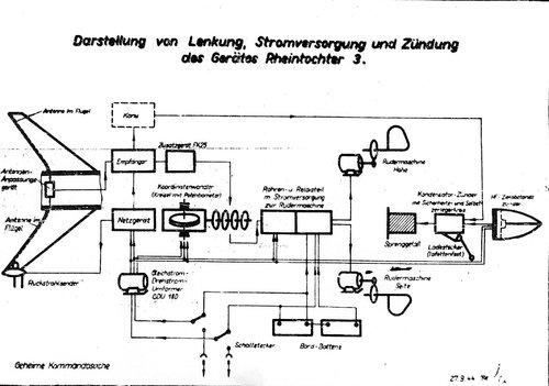
The missile head was borrowed from the R-1 variant and significantly upgraded. It housed a rechargeable battery, a three-phase converter that fed all the equipment, a radio control system, a non-contact Canoe fuse, a gyroscope and electric steering machines. The rudders deviated by angles of ± 10 ° at a speed of 30 °.
The launch weight of the rocket is 1830 kg, of which the second stage is 1050 kg. At the end of the active section, the missile launcher accelerated to 450 - 470 m / s, climbed more than 10,000 m and had an inclined range of 20 ... 25 km. At the beginning of 1945, an order was received: by February 20, 1945, to deliver 15 R-3F missiles to Peenemuende. But they did not manage to work out the rocket.
In parallel with work on R-3F, its solid-fuel version of R-3F was developed.
For this sample, the instrument compartment, wings, and starting boosters remained the same as those of the R-3F. To achieve a predetermined firing height of 12 km, the charge mass was required to be increased to 450 kg and the engine operating time to 40 s. To achieve these parameters, the checker must have a large arch thickness and an outer diameter of 500 mm. The press technology for producing powder bombs that was used at that time could not solve this problem. We worked out two ways to get out of this situation.
In the first case, a transition to non-volatile solvents such as trotyl was possible. At the same time, the checker was made by casting, which removed the restriction on its diameter and length.
In the second case, a checker of six to eight powder modules was used. This was a pioneering invention, which subsequently found wide application in the creation of large solid propellant solid propellant solid propellants.
The engine thrust was about 21 kN (2060 kgf) for 40 s. This allowed the 2nd stage weighing 1120 kg to maintain a high subsonic flight speed. The warhead remained unchanged and was located in the tail.Rheintochter RIII’s liquid-fuel rocket engine on display at RAF Cosford. (
Last edited:
Grzesio
ACCESS: Secret
Something is wrong with the data. Burning 170 kg of diglicol fuel in 0.9 s should produce medium thrust around 335 kN.The starting accelerator weighing 390 kg contained 170 kg of diglycol gunpowder. Within 0.9 s, he developed a thrust of the order of 143 kN (1450 kgf).
Last edited:
pathology_doc
ACCESS: Top Secret
- Joined
- 6 June 2008
- Messages
- 1,561
- Reaction score
- 1,415
Something is wrong with the data. Burning 170 kg of diglicol fuel in 0.9 s should produce medium thrust around 335 kN.The starting accelerator weighing 390 kg contained 170 kg of diglycol gunpowder. Within 0.9 s, he developed a thrust of the order of 143 kN (1450 kgf).
Could be the difference between ideal results with an ideal nozzle and combustion chamber vs. the results they actually got at the time?
Grzesio
ACCESS: Secret
No, it could not.  German solid fuelled rocket engines generally had actual specific impulse in the order of 170-200 kG s/kg (the latter value can be considered a little bit idealistic already
  ). Specific impulse for the R3 booster data given above is just 77 kG s/kg, what is a ridiculously low value.
Last edited:
- Joined
- 27 May 2008
- Messages
- 1,121
- Reaction score
- 2,257
While your physic/maths is correct for what you’ve written, I don’t believe that was what was originally claimed. I think the initial thrust peaked in 0.9 seconds at 143Kn after which it reduced. This is achieved by shaping the charge geometry relative to the combustion chamber volume.Something is wrong with the data. Burning 170 kg of diglicol fuel in 0.9 s should produce medium thrust around 335 kN.
The Isp is petty poor but diglycol gunpowder, likely extruded, is fairly primitive. I always thought “Rocket Rolfs” preferred propellant at the time was diglycol-dinitrate.
Edit - Just found a reference that diglycol gunpowder is diglycol-dintrate which I understand is generically”Diglykol”.
Last edited:
T. A. Gardner
ACCESS: Top Secret
- Joined
- 18 February 2021
- Messages
- 1,041
- Reaction score
- 1,814
That is a Conrad Zg 613A01 / RLM 109-613 liquid fuel rocket motor. It was used on the Rheintochter III, among other missiles.Anyone know what the item is on the small grey trolley?!
Regards,
Barry
Grzesio
ACCESS: Secret
By the way, a question that has been intriguing me for more than 20 years now.
The Preserved Axis Aircraft web site (https://axis.classicwings.com/) lists under preserved German missiles a Rheinmetall-Borsing Rheintochter R 3 owned by the Roswell Museum, NM, USA, with no further details.
I strongly doubt, it could be a real R 3 - but do you probably know, what missile they actually have (if any)?
T. A. Gardner
ACCESS: Top Secret
- Joined
- 18 February 2021
- Messages
- 1,041
- Reaction score
- 1,814
That would depend on which fire control system was being used. If you are using one of the optical systems with MCLOS like say, Bergund, I'd put the success rate at <5%. With radar and MCLOS it might get to around 10%. Without an actual guidance computer in the loop, and Germany was nowhere close to having one for a SAM in 1945, the success rate for any SAM would be quite low.question, does anyone have an estimated hit-rate for the Rheinhochter R3? I remember reading it in a website a few months ago, but can't recall where.
T. A. Gardner
ACCESS: Top Secret
- Joined
- 18 February 2021
- Messages
- 1,041
- Reaction score
- 1,814
I don't know that there even is a Rheintocther there. The only three I know of are one in the Smithsonian, another at the RAF museum, and one at the German museum in Munich. All three are the R I / II version. The only thing at the Roswell Museum are several of Goddard's pre-WW 2 experimental rockets.By the way, a question that has been intriguing me for more than 20 years now.
The Preserved Axis Aircraft web site (https://axis.classicwings.com/) lists under preserved German missiles a Rheinmetall-Borsing Rheintochter R 3 owned by the Roswell Museum, NM, USA, with no further details.
I strongly doubt, it could be a real R 3 - but do you probably know, what missile they actually have (if any)?
Scott Kenny
ACCESS: Above Top Secret
- Joined
- 15 May 2023
- Messages
- 8,788
- Reaction score
- 9,668
The first description makes it sound like there's just a proximity fuze in there:That would depend on which fire control system was being used. If you are using one of the optical systems with MCLOS like say, Bergund, I'd put the success rate at <5%. With radar and MCLOS it might get to around 10%. Without an actual guidance computer in the loop, and Germany was nowhere close to having one for a SAM in 1945, the success rate for any SAM would be quite low.
Schemes of anti-aircraft missiles of the Reintochter series R-3:
1 - distance sensor with heat-resistant fairing;
The second description sounds like MCLOS, and that's not a very effective system, ever.
The missile head was borrowed from the R-1 variant and significantly upgraded. It housed a rechargeable battery, a three-phase converter that fed all the equipment, a radio control system, a non-contact Canoe fuse, a gyroscope and electric steering machines. The rudders deviated by angles of ± 10 ° at a speed of 30 °.
T. A. Gardner
ACCESS: Top Secret
- Joined
- 18 February 2021
- Messages
- 1,041
- Reaction score
- 1,814
The first description makes it sound like there's just a proximity fuze in there:
Nope. The Germans wanted to fit one, very likely could have too given the room available for one. They also dabbled with possibly using command detonation using a ground radio signal.
The second description sounds like MCLOS, and that's not a very effective system, ever.
All of the existing German guidance systems relied on MCLOS making guidance pretty marginal. They'd of been better off using a beam rider but lacked the really requisite millimeter radar with automatic control. They really needed something like the US SCR 584 to pull that off.
Sgt_Miller
ACCESS: Confidential
- Joined
- 17 November 2019
- Messages
- 51
- Reaction score
- 73
Didn't they have short-wavelength fire control radar late into the war? I believe it was a derivative of the Berlin radar, which itself was based on the H2S radar. But I don't know whether or not the automatic control function was availableNope. The Germans wanted to fit one, very likely could have too given the room available for one. They also dabbled with possibly using command detonation using a ground radio signal.
All of the existing German guidance systems relied on MCLOS making guidance pretty marginal. They'd of been better off using a beam rider but lacked the really requisite millimeter radar with automatic control. They really needed something like the US SCR 584 to pull that off.
T. A. Gardner
ACCESS: Top Secret
- Joined
- 18 February 2021
- Messages
- 1,041
- Reaction score
- 1,814
They built a few sets most of which used captured British / US magnetons (from shot down aircraft) but didn't really get any into service before the war ended. They didn't have any that could do automatic control / tracking of a target like the SCR 584 could.Didn't they have short-wavelength fire control radar late into the war? I believe it was a derivative of the Berlin radar, which itself was based on the H2S radar. But I don't know whether or not the automatic control function was available
An example of a millimeter set they were testing is Kulmbach:

This was a 10 cm set. Something like 3 to 5 were produced.
Two "Flakleitanlagen Egerland" (AAA control system) were in service 1945 near Hannover and Hamburg. Both included the "Rundumsucherät Kulmbach" (FuMG74) visible in the foreground of the photo, the"Flakzielgerät Marbach" (FuMG 76) in the background, and the Bedienungswagen(service trolley)74/76 Bayern".They built a few sets most of which used captured British / US magnetons (from shot down aircraft) but didn't really get any into service before the war ended. They didn't have any that could do automatic control / tracking of a target like the SCR 584 could.
An example of a millimeter set they were testing is Kulmbach:

This was a 10 cm set. Something like 3 to 5 were produced.
Similar threads
-
New book - Sonderwaffen - Experimental guns, rockets and missiles used by the Luftwaffe during World War Two.
- Started by Justo Miranda
- Replies: 35
-
-
-
German Wire-Guided Missiles of WW2
- Started by panzer1946
- Replies: 47
-


