Raytheon / E-Systems CM Concept C-135

circle-5

ACCESS: Top Secret
Top Contributor
Senior Member
Joined
31 May 2009
Messages
1,156
Reaction score
554
Another concept model with no information. The pair of small jet engines under the wing roots presumably run generators to power all the SLARs, as in the RC-135E Rivet Amber. But it's obviously not Rivet Amber.

I looked through several years of the National Enquirer, but came up empty. Any suggestions would be welcomed.
 

Attachments

  • e-Systems CM C-135.jpg
    e-Systems CM C-135.jpg
    154.9 KB · Views: 517
Are those "small jet engines" or are they some sort of air sampling device? I doubt they are jet engines, additional power could easily be generated by additional apus in the fuselage. I have seen pictures of some EC-135s that had two apus installed in the rear fuselage.
 
ksimmelink said:
Are those "small jet engines" or are they some sort of air sampling device? I doubt they are jet engines, additional power could easily be generated by additional apus in the fuselage. I have seen pictures of some EC-135s that had two apus installed in the rear fuselage.

Because of the pod locations and the number and size of radar fairings, my vote goes to GE J-85s (or equivalent) for dedicated electrical power. The RC-135E had one J-85 under the left wing and a heat exchanger under the opposite wing, to help cool the massive, seven-megawatt radar transmitters.

See attached photo.
 

Attachments

  • Boeing RC-135E Rivet Amber.jpg
    Boeing RC-135E Rivet Amber.jpg
    62.1 KB · Views: 457
I'll second what Circle-5 has already noted. Another issue with Rivet Amber was the added shielding required to protect the crew from the radar's output - a significant weight gain. I would also guess that running power cables from an APU (and having an APU large enough for the power requirement) at the aft end of the aircraft thru the portion of the fuselage where the crew stations and equipment were installed would/could be a problem along what to do with the heat exchanger installation. All that additional weight strung out through the aft section of the aircraft was avoided with the J-85 and heat exchange installation on the inboard leading edges of the wing. I suppose a little extra thrust from the J-85 didn't hurt either!

What's sad is that the aircraft and its crew were lost on a ferry flight - there was a known structural issue with the vertical fin and the decision was made to ferry the aircraft to Alaska to make the repairs/modifications instead of doing them onsite. Though no specific cause for the loss was ever determined, the evidence suggested that the loss of the vertical fin was the culprit.

Enjoy the Day! Mark
 
Rivet Amber's external podded APU was a T55-L-5 turboshaft engine driving a generator supplying 350kva power. It would be impossible for the J85 to supply enough torque through its accessory drive gearbox to drive this size generator.
 
aim9xray said:
Rivet Amber's external podded APU was a T55-L-5 turboshaft engine driving a generator supplying 350kva power. It would be impossible for the J85 to supply enough torque through its accessory drive gearbox to drive this size generator.

I obtained my information about the RC-135E's J-85 from Wikipedia, right here. I reasoned that if it's on the Internet, it must be true! Thank you aim9xray for the correction. Now if only I knew what this "High-Power CM Concept" model was about -- perhaps an improved replacement for the Rivet Amber aircraft? As Mark noted, the one and only RC-135E was lost at sea (in 1969).
 
Thanks Craig for the power source correction.

Would be nice to know when this model/concept was proposed too.

Enjoy the Day! Mark
 
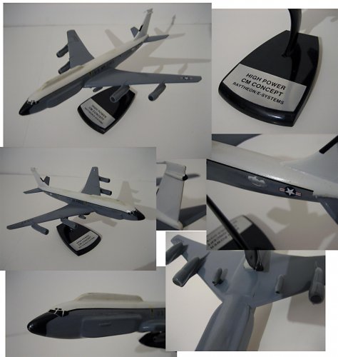
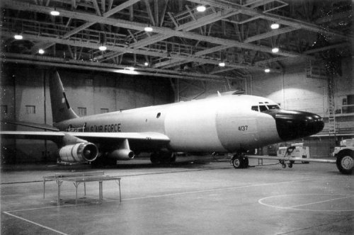
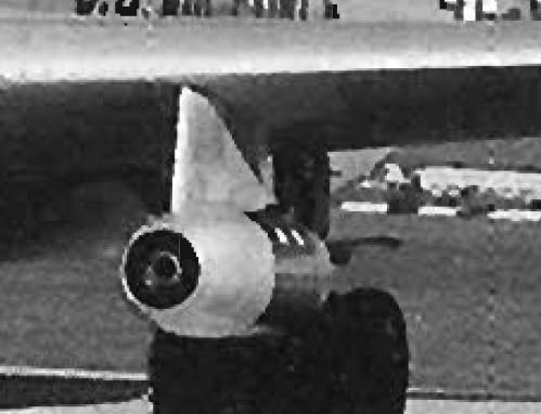
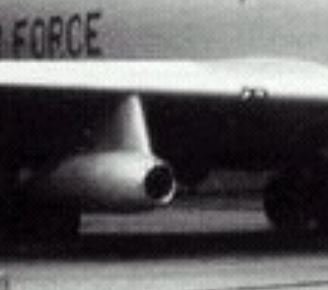
After checking all my sources, the pods would seem to be different from each other, at least on the RC-135E. The pod on the port (left) wing contained a T-55-LS turbine engine powering an electrical generator set. The pod on the starboard wing contained a radiator that helped dissipate the heat generated by the Hughes radar and its associated equipment. This would seem to be borne out by the pictures of the pods in that they look different.

Also the cause of the loss of Rivet Amber was never resolved but two of my books mention that it is was believed (most likely cause) that a failure of the fiberglass radome structure was to blame.
The crash report states: "On June 5, 1969, Rivet Amber departed Shemya for a flight to Fairbanks for routine maintenance. About thirty minutes after departing Shemya, Rivet Amber (callsign Irene 92) transmitted the following message to Elmendorf AFB: "Elmendorf Airways, Irene 92 experiencing vibration in flight. Not certain of the emergency. We have the aircraft under control, Irene 92." This was the last radio contact with the flight. Unidentified microphone keying clicks continued until 10:22. The aircraft crashed at sea."

Sources:
http://aviation-safety.net/database/record.php?id=19690605-0
KC-135 Stratotanker in Action - SSP 118 - by C.M. Reed
Boeing KC-135 Stratotanker - More than just a tanker - Aerofax - by Robert S. Hopkins III
 

Attachments

  • Port.JPG
    Port.JPG
    32.2 KB · Views: 189
  • starboard.JPG
    starboard.JPG
    17.4 KB · Views: 185
circle-5 said:
Another concept model with no information. The pair of small jet engines under the wing roots presumably run generators to power all the SLARs, as in the RC-135E Rivet Amber. But it's obviously not Rivet Amber.

I checked all my books and nothing mentions this version, but it clearly looks like a further development of the RC-135 concept. It has the cheek radomes of the U,V, & W models, but adds the dorsal fairing which could house optical trackers, another form of radar, or even a laser tracking system. Who knows? It would be interesting to find out.
 
It also appears to have the wing tips of the RC-135U.
Related to Big Crow perhaps (with "CM" as in countermeasures)?
http://www.spyflight.co.uk/nck135e.htm
 

Similar threads

Please donate to support the forum.

Back
Top Bottom