PRESSURE JET ENGINE

KHambsch

ACCESS: Confidential
Joined
11 May 2020
Messages
157
Reaction score
167
This is the first iteration prototype (iteration) of this concept. As seen in the video (see link below), there are two "hot fire" runs...one with and one without thrust augmenter. Additionally, there is a bypass shroud, (not seen in this video), which both cools the combustor, heats and ejects ambient air. This works in concert with the augmenter at the end of the tail pipe. , Kevin
View: https://youtu.be/m65aLgQrwXA
 
Last edited:
Great demo, but what are we looking at? How does it work? Why the very odd flame colour?
 
Great demo, but what are we looking at? How does it work? Why the very odd flame colour?
Hi ZT, there are no moving parts on this engine. What you see is three components Tailpipe combustor and intake. For this prototype liquid propane is fed into a stainless steel coil in side the combustor, where is is super heated. (I think the shadow of the coil can be seen in the vid).
This super heated (now gaseous) fuel is piped to the front of the engine vis-a-vis an insulated pipe (same pipe a the internal coil) The pipe is turned 180° to aim directly at the intake tubes. An underexpanded nozzle is connected to the hot gas tube. The exit velocity is calculated to be just over 2 Mach. The SS super heated fuel carries a good deal of kinetic energy and also "wants" to expand quickly.
There are three intake tubes, the second of which is the longest. Each tube is flared to ease intake of ambient air. By the time the fuel has made it to the bottom of the third stage tube, it has "picked-up" 16 parts air to it's one part of fuel. As the third intake is a convex cone 7.5° included angle, the fuel/air mixture velocity is slowed, but at high pressure. This high pressure supresses combustion/ combustion gases for coming out of (retrograde) the combustion chamber. This forces all combustion expansion out the back of the engine/TP.
I did forget to mention that a ram shroud is on the front of the engine. Right now, the engine at static full power ...(using the imperial system) consumes 1lb.f/1lb.thf/1hr , but, ram pressure reduced this significantly to approx. .33 at 400 mph and even less at 500 mph. Hope that explains it. , Kevin
 
Last edited:
Hi Kevin. To the untrained observer, it does look and sound a lot like a PDE. Have you made any progress in evolving the design since 2018?
 
What’s the pressure ratio ? And what”s the mechanism that maintains the pressure ratio?
 
What’s the pressure ratio ? And what”s the mechanism that maintains the pressure ratio?
Hi ZT, this engine doesn't work on the principle of compression, but, instead, leverages the SS fuel flow to transfer it's momentum to ambient air. As you can hear there is frequency at which the engine "operates" at....this it related primarily to the 2nd stage intake tube length, where most of the kinetic fuel to air energy transfer takes place. As you know flow through a tube with open ends creates a wave. This wave travels through the engine and is not only part of the mechanism to prevent combustion reflux at the third stage intake but also obviates the need for a flame holder in the engine. I've been able to test at 200 mph with the combustion not even flinching.
I wanted to remain pure to not having any moving parts in the engine, but think ultimately, a turkey feathers talepipe will be needed instead of a straight pipe.
The liquid metering jet for this engine is .055" D and the hot nozzle is x 4 the area at .116" D. Underexpanding the hot nozzle promotes the formation of shock diamonds and disks.... which promotes the formation of the wave(s) in the 2nd (primary) intake. (If I understand the theory correctly.)
Up coming changes:. 1) expand the end of the hot nozzle to promote a higher injection velocity
2) change tailpipe to expansion chamber type instead of straight pipe.
The whole idea behind this is to construct a fuel efficient ramjet type of engine that can generate static thrust. ,. Kevin
 
Hi Kevin. To the untrained observer, it does look and sound a lot like a PDE. Have you made any progress in evolving the design since 2018?
Hi sublight, the rythm/operating frequency you hear is related to a wave created in the second (main) intake tube (see below.) This wave acts to prevent combustion from refluxing through the third stage diffuser, and to modulate combustion flow through the engine. The wave creation in the intake obviates the need for a flame holder. We tested to 200 mph, with combustion remaining solid.
I've been in the process of moving, so I've not yet altered the engine design. What is planned however, is to
1) expand the injector nozzle to increase overall SS fuel injection velocity. and
2) create a convergent/divergent expansion chamber type tailpipe.
This whole idea was to make a fuel efficient ramjet type engine that could produce enough static thrust to operate a jet aircraft. In fact we already have purchased a complete airframe (to start with) for fast taxi engine testing. Engine testing with changes coming this year. Below is a close-up of the intake system (hot fuel tube seen just above first and second stages, construction phase before the180 turn, insulation and installation of the hot fuel SS nozzle.) , Kevin

1615153557530.png
 
Last edited:
No pressure ratio, so the mass flow purely is a function of the fuel flow? So what’s the difference between this and a blow lamp?
 
Just a clarification re nomenclature....blow lamp = blow torch? If, blow torch, I'm not quite sure how much thrust a blow lamp/torch produces...I guess the best you could call this would be a hybrid INJECTOR rather than EJECTOR acoustic pressure wave jet engine. In Imperial units this engine with the bypass shroud and thrust augmenter produces ~18 foot-pounds thrust and is approx. 6.5 lbs. in weight. This is static thrust and since there is no turbine to act as a governor on the engine, any ram air pressure the engine comes by is used to generate more thrust. It can't be called an ejector ramjet as the 100% fuel is injected at the front of the engine. Additionally, the intake system produces a primary sinewave which acts a driver/ing (?piston?) pushing through the engine. Resonance would be undesirable if produced in an ERJ, where this engine exploits it.
I hope this helps. , Kevin
 
Last edited:
This is the only doc I have re an actual pressure jet engine (unfortunately a 2D study), but gets the point across.
Two things different when compared to my first prototype 1) Intake is not staged and 2) the paper indicates a convergent nozzle only, where mine has a straight length to produce back pressure. Kevin
https://apps.dtic.mil/dtic/tr/fulltext/u2/751317.pdf
 
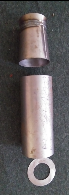
2nd prototype ….here is a pic of the combustion chamber and con/div-ergent nozzle sec. Intake not seen. Haven't tested it yet. This has the same combustion volume as the first CC and TP. Intake and exhaust diameters slightly larger+ slight increase in fuel injection volume (no change in backpressure)..approx. 11 Bar. While for this iteration I think a flame holder might be prudent, I'm thinking of VGs in the 3rd stage intake instead of a traditional type.
1615149846650.png
 
Is this kin to the elegant 'trombone shaped' pulse jets built by that NZ guy ?
IIRC, authorities convinced him to not continue so publicly, as the 'non-rotating' makings would suit DIY cruise-missiles...
 
Is this kin to the elegant 'trombone shaped' pulse jets built by that NZ guy ?
IIRC, authorities convinced him to not continue so publicly, as the 'non-rotating' makings would suit DIY cruise-missiles.

Is this kin to the elegant 'trombone shaped' pulse jets built by that NZ guy ?
IIRC, authorities convinced him to not continue so publicly, as the 'non-rotating' makings would suit DIY cruise-missiles...
I can't remember his name, but he does live in New Zealand...the company is Aardvark.. The trombone shaped engine you're talking about is a Hiller valveless Pulse Jet engine.The engine that you mention ( possibly for cruise missiles ) is called Xjet. I don't know if the authorities have spoken to him about not showing it. Now that you mention it it sounds allot like mine. His Xjet has high Cadence compressions of sorts very high frequency and the valves are shielded somehow from the combustion to allow them to last longer. The X jet is a valved type Pulse Jet engine, and can't be throttled.
The pressure jet engine is throttlable but does produce most of its thrust at the higher end. There are no moving parts in the pressure jet engine, and it increases thrust with ram-air.
Ultimately, for pressre jet, I think a variable area "turkey feathers" type nozzle and some type and flame holder will be called for. Am going to try VGs in the 3rd stage intake before moving to a traditional type holder. Kevin
 
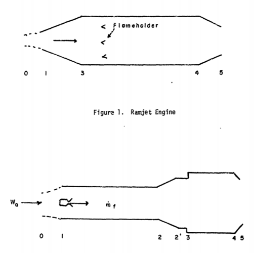
The graphic gives the basic idea of a pressure jet engine vs. a ramjet engine, (ramjet above, pressure jet below) Of course, I've made significant modifications to my design. Performance is 3:1 T/W static and progressively higher T/W with recovery of ram air.
E.g. (Imperial units), at 200 MPH, ram-pressure = 102.4 lbsf./sq.ft., and at 400 MPH this increases significantly to 409.6 lbsf./sq.ft. The % of dynamic ram-air pressure collected becomes the key to significant drop in SFC. Unlike the ramjet that consumes ~4 lbs. fuel/lb. thrust-force/hr. The pressure jet consumes ~ 1 lb. fuel/lb. thrust-force/hr. in static mode. , KH


1615784189183.png
 
Last edited:

Similar threads

Please donate to support the forum.

Back
Top Bottom