Hood

ACCESS: Top Secret
Staff member
Senior Member
Joined
6 September 2006
Messages
4,605
Reaction score
8,577
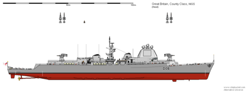
As I hate cluttering up the NIGS thread with speculative what-ifs I have finished my tinkering with Hampshire rebuilt with the NIGS as depicted by portions of the NIGS plans.
The only non-NIGS radars are for 978 for surface-search and a Mk 10 IFF antenna and the ESM systems. I kept both 'Cooky' jammers too. The illuminators are all forward (2 side-by-side superimposed). It all fits rather more smoothly than I anticipated. I think a single-end ship could easily retain a helicopter or some form of ASW armament.
 

Attachments

  • County NIGS.png
    County NIGS.png
    24 KB · Views: 298
that looks fantastic, thanks Hood. Just a couple of observations:

1) Based on the original drawings I think you can clean up the fantail, raise it by a deck and then have a helicopter hangar immediately aft of the aft NIGS launcher with its roof at the same height as the roof of the NIGS magazine/at the deck level of the NIGS launcher. This would give the empty two deck high space seen on the original drawings, that leads out onto the fantail - that I believe is space for a helicopter hangar. It would also give the ship a handsome, if bulky, flush deck appearance with the fantail following the line from the bow, which is what I think the drawings show.

2) I think the radar blockhouse needs to be split in two given the comments about power going to both ends of the ship, the aft facing arrays either need to be between the funnels amidships or aft of the aft funnel, amidships seems most likely. Perhaps, in both scenarios, with the relevant (forward in my opinion) funnel integrated with the superstructure housing the radar? The amidships mast could be relocated to the forward superstructure and integrated with it in a way that eases placement of the directors? I also like the idea of angling the arrays 45 degrees from the centreline as in every post Tico AN/SPY-1D ship. Just as a reference point, I note that HMS Bristol actually has a highly angled bridge superstructure with only a very narrow forward facing section. In addition to potentially helping with interference from the launchers it would probably help with firing arcs. It might also be neccessary to raise thebidge and radar blocks by another deck.

Are the arrays you depict 20ft wide by 15ft high?
 
Last edited:
Frankly I'm impressed, as I'm struggling again to turn anything out that doesn't take days of solid effort. Time I just don't have. A few hours here an hour there weeks will pass before I get anywhere.

I'm starting to yearn for my old drawing board as this is depressing.
 
Agree. I recently stared trying to do the USS Des Moines Typhon refit, cause surprisingly no one has done that, and damn its hard. Probably should have started with the CG(X). But since starting my respect for those who can do this type of things.
 
I also like the idea of angling the arrays 45 degrees from the centreline as in every post Tico AN/SPY-1D ship.

I've been thinking about this since reading yesterday's stuff in the original NIGS thread. If you put the arrays at 45 degrees, then the overlaps in beam coverage are centred fore and aft and on the beam. That's probably more tactically useful and more tolerant of system failures affecting a single array than arranging the arrays fore-and aft and centring the overlaps 45 degrees off axis. There aren't just aesthetic reasons favouring diamond vs square layout.
 
Nice work Hood!

One (possible) niggle: it appears the forward radar array would be directly irradiating the missiles on the forward launcher at even modest elevations. I'm no expert on EMI, so this may not be an issue.
 
Nice work Hood!

One (possible) niggle: it appears the forward radar array would be directly irradiating the missiles on the forward launcher at even modest elevations. I'm no expert on EMI, so this may not be an issue.
It's not irradiation but induction of currents and temperature.
Powerful radio emitters are not a million miles away from your microwave.
Ever leave a spoon in your microwave and turn it on?

In fact the birth of microwave ovens was after certain accidents with early radar.
 
that looks fantastic, thanks Hood. Just a couple of observations:

1) Based on the original drawings I think you can clean up the fantail, raise it by a deck and then have a helicopter hangar immediately aft of the aft NIGS launcher with its roof at the same height as the roof of the NIGS magazine/at the deck level of the NIGS launcher. This would give the empty two deck high space seen on the original drawings, that leads out onto the fantail - that I believe is space for a helicopter hangar. It would also give the ship a handsome, if bulky, flush deck appearance with the fantail following the line from the bow, which is what I think the drawings show.

Let me have a look at the plan again and I will get back to you. The blockhouse behind the NIGS magazine certainly seems too small to be a hangar. I would think at least a single Wessex would be desired.

2) I think the radar blockhouse needs to be split in two given the comments about power going to both ends of the ship, the aft facing arrays either need to be between the funnels amidships or aft of the aft funnel, amidships seems most likely. Perhaps, in both scenarios, with the relevant (forward in my opinion) funnel integrated with the superstructure housing the radar? The amidships mast could be relocated to the forward superstructure and integrated with it in a way that eases placement of the directors? I also like the idea of angling the arrays 45 degrees from the centreline as in every post Tico AN/SPY-1D ship. Just as a reference point, I note that HMS Bristol actually has a highly angled bridge superstructure with only a very narrow forward facing section. In addition to potentially helping with interference from the launchers it would probably help with firing arcs. It might also be neccessary to raise thebidge and radar blocks by another deck.

Are the arrays you depict 20ft wide by 15ft high?

I was in two minds about a split or single blockhouse. Its frustrating that the snippets we have show nothing of any aft array block.
I have based this directly off the NIGS launcher plan which shows the fore edge of the superstructure block. It seems to indicate a flat angled front so I went with arrays parallel to the main axes of the ship. The base of the block seems to be 27ft assuming the bridge structure is the same width as the magazine block. That gives room for the array and 3.5ft of space around it on either side. Here comes the rub, if all the radar arrays are angled 45 degrees then the side panels will be angled back the same amount, the taper would soon prevent an array being fitted (I haven't calculated it but the edge of the top deck would be smaller than 20ft I would think).
So either; a) the drawing really is generic, b) your angled array argument makes more sense in that context.

If we go with the angled array approach its possible an aft block could be fitted just ahead of the aft funnel, perhaps becoming part of the radar block structure as a mack, would solve the rear illuminator problem too.
I have to admit I am not happy with the current layout, while plausible it feels too constrained, as you and Starviking point out the forward array seems too low and in general the fore and aft radars would cause problems, we're dealing with the most powerful naval radar Britain has contemplated and I feel it would need clearer arcs to avoid all kinds of problems. I have tried to reconstruct what the plan shows as a best guess to the designers intentions at that point in time. Its in no way an optimised NIGS destroyer/cruiser. But I will play around with the twin block idea some more.

Yes I began with 20 x 20ft but edited to 15ft high when you mentioned that in your recent post.
For those who don't know much about Shipbucket, the scale is 2 pixels = 1 foot, so here the arrays are 40 x 30 pixels.

Frankly I'm impressed, as I'm struggling again to turn anything out that doesn't take days of solid effort. Time I just don't have. A few hours here an hour there weeks will pass before I get anywhere.
Don't give up, it took me tinkering all week to produce this, much of the time was agonising over the details and getting them as plausible as possible.
 
Hood As usual you have played a blinder. I have some thoughts which may or may not be helpful:

MACKs These were shown on CVA 01 and the 1966 cruisers. I think they would have been used to declutter the mast area and give a places to put any radars.

MATCH I think a platform for Wasp would have been provided aft

Guns I agree that no guns would have been fitted (as in Type 22 and the 1966 cruisers)

Seacat Same basic fit as Countys fine

Radar I tend to think that the RN would have gone for a housing like the Dome on CVA01/Type 82 over an extended flag style bridge. With the Macks being used, this can be further back than on the County. Fire Control Radars could have been stepped on the aft Mack and in front of the Dome.

Although JFC does nt like it I still think an updated version of your double ended Seaslug cruiser on Shipbucket would be a nice alternate, using the earlier in service dates for Seaslug in an alt world
 
I think a dome over some sort of earlier STAR type radar is a possibility. Would be bigger than Type 988 though.
 
Its just I think that the AEGIS Pyramid is a bit too advanced for the mid 60s. You could go for the Long Bridge Style look or possibly the cone style of the TYPHON Radar.
 
I was trying to think of when the RN started looking at Macks, the earliest I can think of is the proposed Daring reconstructions of 1960.
So this being around 1959-60 is in the right ballpark area for them to be looking at Macks.
All this ship needs is a somewhere to put the jammers, ESM and somewhere with good arcs for the surface-search/navigation set, so it wouldn' have to be a a particularly big or complicated Mack.
 
In the early 60s you are still talking Nike Zeus if I remember right.
 
The blockhouse behind the NIGS magazine certainly seems too small to be a hangar.
Weren't the Royal Navy/MOD considering a British counterpart to the QH-50 DASH at one stage?
MATCH (Manned Torpedo Carrying Helicopter) in the form of the Westland Wasp is the exact British equivalent to the QH-50 DASH.
 
2) I think the radar blockhouse needs to be split in two given the comments about power going to both ends of the ship, the aft facing arrays either need to be between the funnels amidships or aft of the aft funnel, amidships seems most likely. Perhaps, in both scenarios, with the relevant (forward in my opinion) funnel integrated with the superstructure housing the radar? The amidships mast could be relocated to the forward superstructure and integrated with it in a way that eases placement of the directors? I also like the idea of angling the arrays 45 degrees from the centreline as in every post Tico AN/SPY-1D ship. Just as a reference point, I note that HMS Bristol actually has a highly angled bridge superstructure with only a very narrow forward facing section. In addition to potentially helping with interference from the launchers it would probably help with firing arcs. It might also be neccessary to raise thebidge and radar blocks by another deck.

I have not done a pixel by pixel count but comparing that empty block of space with the size of the NIGS missile and the magazines I think it is the perfect, if tight, size for a folded Wessex in terms of length and width. If we imagine the hangar space being the same width as the full width NIGS magazine we could make it a double hangar for Wessex. Obviously thats speculation and would drive accommodation needs etc. Either way, I am sure the fantail is one deck higher and follows the line from the bow right the way to the stern.

I was in two minds about a split or single blockhouse. Its frustrating that the snippets we have show nothing of any aft array block.
I have based this directly off the NIGS launcher plan which shows the fore edge of the superstructure block. It seems to indicate a flat angled front so I went with arrays parallel to the main axes of the ship. The base of the block seems to be 27ft assuming the bridge structure is the same width as the magazine block. That gives room for the array and 3.5ft of space around it on either side. Here comes the rub, if all the radar arrays are angled 45 degrees then the side panels will be angled back the same amount, the taper would soon prevent an array being fitted (I haven't calculated it but the edge of the top deck would be smaller than 20ft I would think).
So either; a) the drawing really is generic, b) your angled array argument makes more sense in that context.

The plan views for the drawings don't show any details of the superstructure (except the missile housings), the vertical cross-section drawings do provide some detail, as you point out, but its a two dimensional slice that I believe is taken down the centreline of the ship. With arrays angled 45 degrees from the centreline the front face of the superstructure would still recline by 25 degrees from the vertical, that could be what the drawings show. Thus, I don't think its possible to say with any certainty that the front face of the bridge is going to be 27ft because the width of the missile housing protruding above the foredeck is 27ft, it could well be less. Hence my earlier reference to HMS Bristol and her very narrow bridge front face and its angled sides. Additionally, just from a practical perspective, not only does radar interference from the launchers seem highly probable (and vice versa) but the exhaust efflux and sheer force from the NIGS boosters would surely wreak havoc if fired directly at the forward facing array - placing the arrays at 45 degrees to the centreline solves that. Also, if you look carefully at the very top of the drawing of the forward launcher for the 64 missile variant it shows what appears to be the top of the superstructure, I am probably overthinking this but I think it shows the bridge at the top, above where we think the arrays are, again this would prevent the bridge being blasted with the rocket efflux from the NIGS boosters.

If we go with the angled array approach its possible an aft block could be fitted just ahead of the aft funnel, perhaps becoming part of the radar block structure as a mack, would solve the rear illuminator problem too.
I have to admit I am not happy with the current layout, while plausible it feels too constrained, as you and Starviking point out the forward array seems too low and in general the fore and aft radars would cause problems, we're dealing with the most powerful naval radar Britain has contemplated and I feel it would need clearer arcs to avoid all kinds of problems. I have tried to reconstruct what the plan shows as a best guess to the designers intentions at that point in time. Its in no way an optimised NIGS destroyer/cruiser. But I will play around with the twin block idea some more.

Agreed, and with the comments above about MACKS as an option. From my perspective, fixing the hangar/fantail, angling the arrays 45 degrees from the centreline, moving the bridge to the top of the superstructure and playing with fore and aft blocks (I think the aft one built around either the fore or aft funnel, possibly the aft funnel with the fore funnel turned into a MACK to get the required height???) is probably as close as we are likely to get. That said, I would love to see 20 or so feet added to the forward bow to house a 4.5" Mk.8.

Thanks again for playing with this.
 
Last edited:
There are a million of never were designs for the various navies and only a handful of artists preferring these ones over the actually built ships. Hence soo few such drawings exists. Myself too have some sort of pride knowing that I was the first one who draw many drawings or drawing sets of designs (All the Lion variants, all the Yamato variants, the Austro-Hungarian Navy never-weres, Australian designs, various British export ones and so on)

Me too thinks that the bridge should be above the RN SCANFAR radars like the top bridge of USS Long Beach. Actually, does Long Beach have two bridges??? One below and one above the radar sets in the block superstructure?
https%3A%2F%2Fapi.thedrive.com%2Fwp-content%2Fuploads%2F2018%2F10%2Fad1xx-coxx1py.jpg%3Fquality%3D85
 
I agree the bridge location has a couple of options.
I went with the low position partly inspired by the minimal bridges that became in vogue around the early 1950s (think Type 15 frigate etc.). The Counties had an unusual arrangement of the enclosed bridge plus wing and a larger open area around the forward funnel as a signal deck.
I have kept the same arrangement here, the signal deck serving as a position for docking etc. I feel even with a bridge perched on top of the block a lower open platform would be needed.
Also, putting the bridge on top sacrifices space for the illuminators plus there are topweight concerns.
Both Counties and Leander's had a closed "turret" bridge for the Officer-On-Watch with the (on Carriers and DLGs) operations room several decks below, accessible by a one-man lift. On your designs the Bridge is fairly low down, and the forward view is blocked by the NIGS Launcher.
 
I have kept the same arrangement here, the signal deck serving as a position for docking etc. I feel even with a bridge perched on top of the block a lower open platform would be needed.
Also, putting the bridge on top sacrifices space for the illuminators plus there are topweight concerns.

Agreed with the top weight issues, it pushes illuminators higher even if it doesn't add much weight in itself. That said, I don't think it has to reduce space for the illumnators if the roof of the bridge deck covers the same area as the top of the radar block house. Bridge wings can still be achieved, as on the DDG51 class, and I can't think of a reason why a signal deck can be included between the forward radar block house and the forward funnel where you have it now.

@Tzoli, what you are seeing on USS Long Beach is the Flag Bridge (for an Admiral and his staff) below the radar arrays at 04 level and the main bridge above the radar arrays at 010 level.
 
Ahh I see. Is there any command equipment at the Admrial's Bridge level or just furniture and meeting halls?

I've not done too much as I had less time but angled the radar pyramid to 45 degrees and it actually looks better now. The red rectangle aft should represent the area required for a Wessex Helicopter 21m x 5m:
ddqhf1l-62d96e64-cd23-478d-8bb7-a4ba2c755cce.png
 
Liking your design Tzoli, right now its got a Soviet Kresta-vibe to it.
 
Tzoli Your drawing is really good. I doubt the RN would have given the ship more than two Seacats. The rest looks good. I still lean toward a 1961 Long Beach bridge and radar fit, square rather than pyramid. Fire control radars like the fit on the Albanys.
But this is all guess work
 
Tzoli Your drawing is really good. I doubt the RN would have given the ship more than two Seacats. The rest looks good. I still lean toward a 1961 Long Beach bridge and radar fit, square rather than pyramid. Fire control radars like the fit on the Albanys.
But this is all guess work
Why do you think that?
When their theory was for the 25 degree inclined arrays.
Sorry, you are right. Radars are not my area. Its just I wanted something with a more 60s look. No logic, sorry
 
By the way what is the issue with mounting 4 Seacat launchers on a hull? I don't think that such a small missile system would be that expensive
 
Hanger for two Wessex helicopters, I've removed the 4th Seacat but repositioned the 3rd one on the centreline so broadside remained the same.
Also added two 40mm/56 Single Bofors Guns. Though 70 calibre ones would be the best as it was intended for the GWS cruisers as well.
ddqhf1l-195970a9-034a-450e-9cbb-b33b991f63a4.png
 
Now it is forming nicely.
Question, do the radar suite okay?
4x Type 985
1x Type 992
1x Type 978
ddqhf1l-8ab506f4-ddaa-4014-bd5c-e93fef69cc75.png
 
The forward part of the Counties, around the gun turrets were the deck had planks or just painted in that brownish-yellowish colours?


glam otw 009 article.jpg

11ec1fb58a9dcf3b433f630a7fcc596f.jpg
 
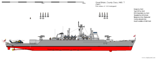
The following is currently incomplete and flawed but is my best effort to date on a County based NIGS ship.
Virtually the whole ship by the hullform, and propulsion is changed to fit everything on, and I suspect I;m missing a lot.

I hope the size of this file is within permitted limits...?
 

Attachments

  • County NIGS 4.png
    County NIGS 4.png
    34.1 KB · Views: 172
@zen, let me just say, wow, that looks great and really well thought out!

Comparing yours and Hood's with the archive drawings I have just realised something that I should have noticed ages ago. In the 64 missile version the forward launcher is lower than the forward launcher on the 82 missile version and lower than the aft launcher in both versions. Only in the 82 missile version are both launchers at the same height. I think Hood has the launchers at the right height for the 82 missile version but the quarter deck one deck too low. Zen has the forward launcher at the right height for the 64 missile version but the aft launcher and quarterdeck are each one deck too low. To summarise:

Aft Launcher:

Both versions: Launcher is 6 decks above the keel, 4 decks above the waterline, 2 decks (sufficient for a hangar) above the quarter deck

Forward Launcher:

64 missile version: Launcher is at the same height as B turret/the mounting for Exocet launchers on the as-built County class and thus lower than the aft launcher

82 missile version: Launcher is half a deck (or a bit more, the hull lines curve down as they move aft) higher than in the 64 missile version and probably flush decked with the aft launcher

As a result, in both the 64 and 82 missile versions the quarter deck should be flush with the line from the bow, rather than being a deck lower as in the Sea Slug ships. There is then two decks between the quarterdeck and the base of the launcher which is sufficient height for a Wessex hangar, the roof of which is flush with the deck on which the NIGS launcher is mounted.
 
I think Hood has the launchers at the right height for the 82 missile version but the quarter deck one deck too low.
Yes I spotted that after posting, actually I think its closer to half a deck too low, either way that is on my list of fixes.

Nice work Zen, I think we are all thinking along very similar lines.
 
Yes I spotted that after posting, actually I think its closer to half a deck too low, either way that is on my list of fixes.

I just did some rough scaling, the deck heights vary but every two decks are approximately 16.5ft of height so the quarter deck should be 16.5ft above the waterline, the hanger roof/deck the launcher is mounted on a further 16.5ft + above that with 16.5ft from the waterline to the keel. The measurements work out perfectly for the forward launcher on the 82 missile variant too, 16.5ft from the keel to the waterline then 33ft to the deck the launcher is mounted on thus making the launchers flush fore and aft as you have shown them in the first post. On the 64 missile variant the forward launcher is just over 4ft lower than the aft launcher.
 
Last edited:
To my knowledge the aft deck of the Counties are one and half lower then the Helideck. Also Fuller how many sketches did you seen about the hulls?
I've based mine entirely on the Counties
 
Last edited:

Similar threads

Please donate to support the forum.

Back
Top Bottom