NASA Ames/USAF Wright Laboratory FLAC/SHARC

flateric

ACCESS: USAP
Staff member
Top Contributor
Senior Member
Joined
1 April 2006
Messages
11,030
Reaction score
8,347
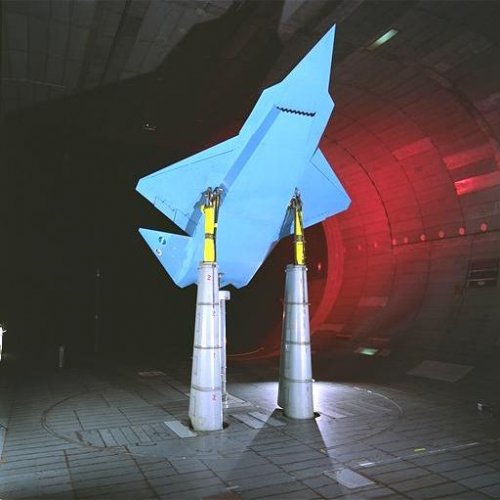
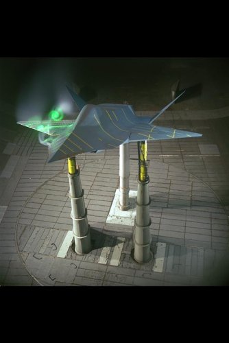
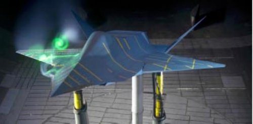
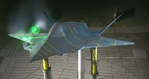
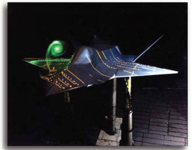
NASA Ames/USAF Wright Laboratory FLAC/SHARC

Many saw these photos but few (OK, at least I) did know the real background.

AIAA Paper 1993-3516

Small-Scale Wind-Tunnel
Investigation of an Advanced
Fighter Configuration Semi-Span Wing

"Fighter Lift and Control (FLAC) program,
a cooperative research effort between
the USAF Wright Laboratory and the NASA
Ames Research Center. The purpose of thls
experiment was to improve the baseline aerodynamics
of the FLAC wing in the angle-of-attack
range typical of maneuver or combat
Passive and actlve boundary layer control devices
were tested to determine their effectlveness
at delaying separation, and hence improving
maxlmum lift coeffclent and lift-to-drag
ratlo. Various sizes and shapes of vortex
generators, Gurney flaps, and other flow control
concepts were tested. The effectiveness of
tangential blowing an the wing upper surface
also was explored using different mass flow
coemclents. The pneumatics and Gurney flap
showed the most promise for improving the
baseline aerodynamics. Placement of the
vortex generators either forward or aft of the
flow separation point had no significant effect
on the baseline aerodynamics due to the
presence of a leading edge separation bubble."

SHARC

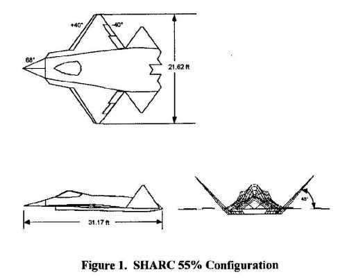
"A large-scale experimental investigation using the 55 percent-scale Subsonic High Alpha Research Concept (SHARC) was
performed in the NASA Ames 40- by 80-Foot Wind Tunnel. The SHARC configuration represents an advanced
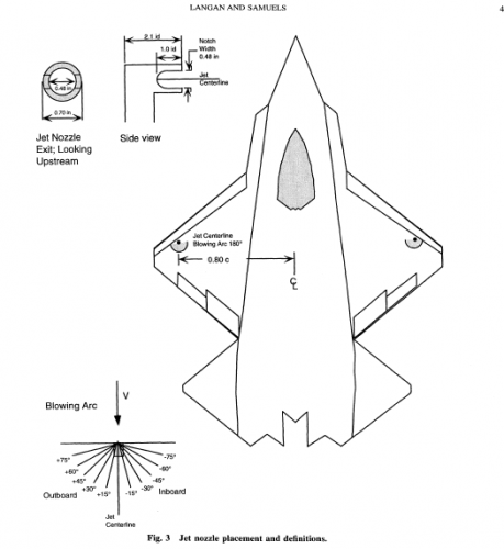
low-observable fighter aircraft, and features a clipped diamond wing with leading- and trailing-edge sweep angles of +/- 40
deg, a chined forebody, leading-edge extensions, and a vee-tail. Data covering the angle of attack range of -4 deg through
+42.4 deg and sideslip angles from -10 deg through +10 deg were acquired at a dynamic pressure of 40 psf. Test data are
presented for symmetric and asymmetric wing jet nozzle blowing. Blowing coefficient values ranged from a minimum of
0.005 to a maximum of 0.020. The results indicate that wing jet nozzle blowing is an effective lift enhancement device,
giving an across-the-board net increase in lift over the entire angle of attack range teated. The jets were also found to improve
the aircraft's drag polar. Roll control using asymmetric jet blowing equaled or exceeded that available via the deflection of
only a single aileron."
 

Attachments

  • SHARC3.jpg
    SHARC3.jpg
    27.8 KB · Views: 1,509
  • AC94-0480-29_a.jpg
    AC94-0480-29_a.jpg
    37.9 KB · Views: 1,413
  • AC94-0480-41_a.jpg
    AC94-0480-41_a.jpg
    52.2 KB · Views: 1,412
  • SHARC 3-view.jpg
    SHARC 3-view.jpg
    37.6 KB · Views: 1,464
Hi,

who can identify this fighter model ?.
 

Attachments

  • FIGHTER.JPG
    FIGHTER.JPG
    20.5 KB · Views: 219
it looks alot like a plane from a Artists rendering of a MD or Northrop concept for either CALF, or just some ASTVOL project I saw once, I’ll think I can track it down somewhere.
 
NASA Ames/USAF Wright Laboratory FLAC/SHARC
http://www.secretprojects.co.uk/forum/index.php/topic,373.0/highlight,sharc.html
 
Interesting:

http://hdl.handle.net/2060/20040077060

Recent airframe noise studies at Ames Research Center and elsewhere have identified flap side-edge noise as an important component of aircraft landing noise. During aerodynamic tests of an Air Force stealth fighter design (called SHARC) in the Ames 40- by 80-Foot Wind Tunnel, it came to our attention that stealth technology might have acoustic attributes. Specifically, the Continuous Moldline Technology (CMT) developed for SHARC eliminates flap side edges by blending the flap and wing trailing edges with a flexible material that is load bearing. This led to a 7- by 10-foot wind tunnel aeroacoustic test of a two-dimensional airfoil with a simple hinged flap with and without a CMT modification. phased microphone array technology (PMAT) acoustic system was installed in the Ames 7- by 10-Foot Wind Tunnel test section wall. The array is designed for visualization of noise sources and determination of their individual strengths. Noise radiation from the vertically mounted windflap model revealed a virtual elimination of the side-edge noise in the flyover direction. Because of the large noise reduction, it was necessary to recess the microphones in order to reduce flow-induced noise and increase the signal-to-noise ratio. A strong Kevlar cloth covered the recess. With this array geometry, noise levels that were 20 decibels below the wind tunnel background noise could be identified.
 
new, hi-res (~3 Mb) images of SHARC/FLAC became available at NASA Ames AILS
use keywords SHARC and FLAC for finding 'em
several extra hi-res variants appeared at http://www.nasa.gov/centers/ames/news/releases/2004/strike/fighter.html

enjoy!
 

Attachments

  • AC94-0480-43 [1280x768].jpg
    AC94-0480-43 [1280x768].jpg
    145.8 KB · Views: 216
  • 77919main_AC94-0480-41 [1280x768].jpg
    77919main_AC94-0480-41 [1280x768].jpg
    150.1 KB · Views: 173
  • AC94-0028-16 [1280x768].jpg
    AC94-0028-16 [1280x768].jpg
    139.9 KB · Views: 146
  • AC94-0028-14 [1280x768].jpg
    AC94-0028-14 [1280x768].jpg
    128.7 KB · Views: 141
  • AC94-0028-13 [1280x768].jpg
    AC94-0028-13 [1280x768].jpg
    132 KB · Views: 131
  • AC94-0028-12 [1280x768].jpg
    AC94-0028-12 [1280x768].jpg
    141.2 KB · Views: 131
  • AC94-0028-11 [1280x768].jpg
    AC94-0028-11 [1280x768].jpg
    158.2 KB · Views: 121
  • AC94-0028-2 [1280x768].jpg
    AC94-0028-2 [1280x768].jpg
    99.5 KB · Views: 1,182
more...
 

Attachments

  • AC99-0026-4 [1280x768].jpg
    AC99-0026-4 [1280x768].jpg
    125 KB · Views: 178
  • 77918main_AC94-0480-29 [1280x768].jpg
    77918main_AC94-0480-29 [1280x768].jpg
    110.5 KB · Views: 181
  • AC94-0480-48 [1280x768].jpg
    AC94-0480-48 [1280x768].jpg
    100.2 KB · Views: 150
  • AC94-0480-45 [1280x768].jpg
    AC94-0480-45 [1280x768].jpg
    98.4 KB · Views: 134
  • AC94-0480-42 [1280x768].jpg
    AC94-0480-42 [1280x768].jpg
    99.2 KB · Views: 202
  • AC94-0480-28 [1280x768].jpg
    AC94-0480-28 [1280x768].jpg
    127.7 KB · Views: 201
  • AC94-0480-27 [1280x768].jpg
    AC94-0480-27 [1280x768].jpg
    119.6 KB · Views: 192
  • AC94-0480-26 [1280x768].jpg
    AC94-0480-26 [1280x768].jpg
    105 KB · Views: 190
What sort of relationship did SHARC have to the MRF program? Was there any intention of taking the design of SHARC and developing it into a full blown combat aircraft?
 
Any one know who the two pilots are in flaterics post talking to some engineer type. Is the young one test pilot Frank T Birk.
 
NASA Ames Machine Shop N-220


meantime,

http://ails.arc.nasa.gov/ails/GetHRES.php?fn=AC94-0480-42.jpg
http://ails.arc.nasa.gov/ails/GetHRES.php?fn=AC94-0480-43.jpg
 
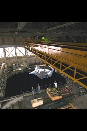
The unidentified man with Lt. Col Perkins who at that time was the F-15 STOL ADPO Director was Col. Robert (forgot last name, but it’s not Frank Birk) Col. Robert was the Aeromechanics Division Director, Flight Dynamics Laboratory, Air Force Wright Aeronautical Laboratory (AFWAL) Wright-Patterson AFB (Area B). Lt. Col Perkins had nothing to do with the Fighter Lift and Control (FLAC) Program which the SHARC model was built for, but he worked for Col Robert ?? and accompanied him TDY to NASA-Ames to see the result of all of money being spent by Col. Robert? Division. The FLAC Program was ran from the Airframe Aerodynamics Group, Aeromechanics Division. The initial FLAC USAF Program Manager, Captain Mike Alexander did what any good Captain does when his boss shows up at his wind tunnel test, puts his Col. next to the SHARC model and have his picture taken. Afterwards, Captain Alexander, Lt. Col Perkins, and Col. Robert ?? went to a local bar pub and got thoroughly wasted had an enjoyable evening. Steve Craft from NASA AMes was given the responsibility of building the SHARC Model at Ames.

The origin of the FLAC (SHARC) concept came from an aircraft designer from the Flight Dynamics Lab’s Mission Analysis and Design Group. The Designer was given a set of requirements to come up with an advanced fighter concept that had stealth qualities. Hence, the FLAC concept had nothing to do with MRF. There was nothing “secret” about the FLAC program or the SHARC model until a commercial partner jointed the team later in the program. Since this FLAC program/design came out just as the F-22 had just won the Advanced Tactical Fighter (ATF) competition, and it was generally known that whatever went into the 40x80 usually ended up in Aviation Week. Knowing this the USAF FLAC Team was very sensitive to the design NOT even closely resembling the F-22. As a matter of fact, the F-22 Chief Engineer called Captain Alexander wanting to know why the FLAC program was trying to improve “his” aircraft (F-22). So, hence the diamond wing planform (ala YF-23) and the fuselage shape similar in shape to one YF-23 nacelle, V-tails (again YF-23) and the forebody similar to the F-117. The SHARC model concept as you know it owes it “lines” to ensure the “Lab Rats” of the Flight Dynamics Laboratory did not “improve” the performance of the best fighter aircraft in the world. The FLAC concept was never meant to be operational. It was only there to produce a flow field that was representative of an aircraft shape to test flow control effectors to improve L/D and maneuvering performance.

The FLAC Program was a multi-Reynolds wind tunnel testing program that investigated forebody mechanical (strakes) and static pneumatic flow control effectors to increase maneuver performance of a representative advanced fighter concept. The investigation began with a water tunnel test at Wright-Patterson, followed by an entry into the NASA-Langley BART tunnel. The next step up in Reynolds number was a wing semi-span entry into the NASA-Ames 7x10 wind tunnel conducted by Kevin Langan. The AIAA Paper quoted above was written by Kevin Langan. Captain Alexander conducted the 10% scale “FLAC” model wind tunnel test in the NASA-AMES 7x10 wind tunnel and that was the first real investigation of the effectiveness of forebody strakes and 3 forebody nozzle blowing concepts. The 10% FLAC model was designed and fabricated at Microcraft in Tullahoma, Tn. Following the FLAC 10% scale model test, came the first entry of the SHARC model in the 40x80 which Captain Alexander and Larry Meyn of NASA Ames conducted. A commercial partner joined the SHARC team and they brought to the table the first generation Conformal Moldline technology which was tested on the SHARC model’s trailing edge flaps. There are a few AIAA FLAC papers (AIAA Paper 94-1854, 10% FLAC model) written as well as a number of USAF technical reports.

As FYI, the individuals in picture AC94-480-48 are as follows (left to right)
1) Birdman (name lost,assigned to FLAC early, but he quit NASA to go and count bird hatchlings in the US National Forrest)
2) Larry Meyn, NASA-Ames FLAC PM
3) Captain Alexander, USAF FLAC PM (civilian clothes)
4) Steve Craft NASA-Ames, PM for the design and fabrication of the SHARC Model
5) Captain Neil Mosberger A peer from the same Group as Captain Alexander (civilian clothes)
6) Name and position lost – He was a member of NASA-Ames

SHARCMaster
 
Was searching for info on nose lengths of combat aircraft and stumbled on this (attached) ..anyone know what it is?
 

Attachments

  • vortex_fighter_plane.jpg
    vortex_fighter_plane.jpg
    26.1 KB · Views: 193
One thing that I noticed that was interesting was that there in the nose, there are some plenums. It looks as if there are some blown slots up there for flow control over the chines.
 
Aeroengineer1 said:
One thing that I noticed that was interesting was that there in the nose, there are some plenums. It looks as if there are some blown slots up there for flow control over the chines.

From SHARCmaster's post upthread;
The FLAC Program was a multi-Reynolds wind tunnel testing program that investigated forebody mechanical (strakes) and static pneumatic flow control effectors to increase maneuver performance of a representative advanced fighter concept. ..... Captain Alexander conducted the 10% scale “FLAC” model wind tunnel test in the NASA-AMES 7x10 wind tunnel and that was the first real investigation of the effectiveness of forebody strakes and 3 forebody nozzle blowing concepts.
 
The 40x80 SHARC Model did have a plenum in the nose. The nose had a total of 6-nozzles (3/side). The 40x80 provided the high pressure air and the mass flow (Cmu) all which was varied. But, the specifics can be found in the aforementioned reports.

The SHARC model had two different blowing schemes in the nose (down selected from the 7x10 wind tunnel test); 1) Tangential (back across the nose surface) and straight out. The tangential blowing worked best.

SHARCMastger
 
SHARCMaster said:
The 40x80 SHARC Model did have a plenum in the nose. The nose had a total of 6-nozzles (3/side). The 40x80 provided the high pressure air and the mass flow (Cmu) all which was varied. But, the specifics can be found in the aforementioned reports.

The SHARC model had two different blowing schemes in the nose (down selected from the 7x10 wind tunnel test); 1) Tangential (back across the nose surface) and straight out. The tangential blowing worked best.

SHARCMastger

Didn't they test something like that on an F/A-18? ???
 
Yes, similar in the fact they tested strakes and forebody blowing, but there is one major difference....the F-18 has a symmetrical forebody, the SHARC model had an asymmetrical forebody with chines. Two completely different flow fields, which means different aerodynamics and aero-control responses. In addition, the forebody of the F-18 was long (long moment arm) while the SHARC model had a short forebody (short moment arm).
 
Hi,


NASA Ames/USAF Wright Laboratory SHARC.


http://arc.aiaa.org/doi/abs/10.2514/2.2446
 

Attachments

  • SHARC.png
    SHARC.png
    45.2 KB · Views: 357
I forgot about the jets outboard on the wings. I am glad to see that Kevin wrote a paper that was accepted in the Journal of Aircraft. FLAC project ended in the early 1990's I believe (It's been a while ago!) and I noticed the paper was presented in 1999. I was 4-years retired out of the AF when this was published. Kevin writes well. I am surprise to see Jeff Samuel was the co-author and not Larry M. from Ames.

SHARCMaster
 
From National Full-Scale Aerodynamics Complex.
 

Attachments

  • 12.png
    12.png
    246 KB · Views: 41

Similar threads

Please donate to support the forum.

Back
Top Bottom