F4H-1F/F-4A, actually. It is aircraft 11; BuNo 145310.

An "A" model? There were only 45 built so I wonder how many of them are left? As for Aircraft 11 that would be one of the early ones with the flat RIO canopy (The backseat position in the first 19 F-4As was quite claustrophobic for the RIO) and it had an AN/APQ-50 radar.
 
Last edited:
All -

I was asssigned to the 122nd Fighter Wing, Indiana Air National Guard @ Ft. Wayne, Indiana. We were the last ANG unit to fly the F-4 ( " E " model ), before they went to the ariel target drone program; or for some of our jets...were ferried straight over to Turkey.

I was the 122nd's Electric Shop Chief not only during Civil Service " Technician " status through the week.... but also during duty on weekends and deployments in MIL pay status.

Amongst the last F-4Es to leave were " 452 ", and " 844 ".
452 had developed a recurring Generator failure ( Lt engine side if I recall ) , and the problem plagued the Electric Shop over a period of months. The Deputy Commander for Maintenance finally reached the end of his tolerance, and demanded an enduring fix be found for 452's Generator-induced aborts. Months of Generator, Generator Control Unit, and Frequency & Load Contol box changes plus random wiring harness checks had all been performed to no avail. I made a list of 212 seperate wiring checks that needed to made, and the DCM agreed to park the jet for as long as it would take to troubleshoot and then fix the plane.

Each suspect wire in the generator(s) systems circuitry.... generator control wiring.... buss wiring, and more....all had their to be checked thoughroughly. That meant Canon plugs and bulkhead connectors for wiring harnesses ( some big as your ankle ) had to be disconnected, plus Canon plugs to numerous components also had to be disconnected to isolate seperate circuits. THEN...EACH wire needed to be ohmic checked to all wires around it....ohmic checked to each Canon plug's metal shell..and ohmic checked to the aircraft structure...to see if wires that carried current were reaching a grounding point along their runs; when they shouldn't be.
And ideally... All wires @ harness flex points would be ohmic tested while the harness was being manually flexed. The latter required 2 mechanics, minimum. For ground wires in the circuit, the max allowed resistance reading on the ohmeter
was 1 ohm.

The test took 2 solid work weeks, where at least I was always present working on the jet. The last wires to be checked, were the 3 large generator output plus 1 large generator ground wire that ran up through the pylon at the front of the ( Lt )
J-79. These wires emanated upward from a grommet in the floor of the LT engine intake. They were wrapped in a greyish-purple nylon anti-chafe tape, for protection inside the tight confines of the generator pylon that contained the wires ahead of the engine face, and mounted the dome that housed the generator.

After 2 weeks of troubleshooting, I had found nothing; and had reached THE final check on THE final wire; which was the ground wire for the Lt generator. The meter read 1.1 ohm.
Not the usual 1 ohm max for a ground wire. I.I ohm.
All those wiring checks...and 1.1ohm resistance on one ground wire is all I found.

I unwrapped the anti-chafe tape from the 4 wire generator leads, to where it ended inside the lower grommet in the intake floor. I saw a dark smudge line on the wires where they made contact inside the grommet, even through they were covered with the anti-chafe tape at that location. The smudges had an appearance and slight texture to them, that resembled a very super-finely ground aluminum dust intermixed with random grease/oil residue. After wiping the smudge on the ground wire, I could still see only the darkened outer harness cloth overing, but no evidence of bare; silver colored wire. The same
smudge residue could be seen inside the nylon grommet, which had a split " C " shape, to aid in installation.

The ground wire did not show any undesired grounding through chafing to any of the generator's 3 phase lead wires.
All I could figure was the the smudge on the ground wire permeated the cloth wire sheath to allow conduction to ground at point in-advance of the established ground point further down in the jet's structure. Then grounding path would have had to include the smudge materiel inside the grommet, to also necessarily include some of it being present inside the split of the grommett...and that allowed the premature grounding to take place. And...the grounding being made read a scant .1ohm over max allowable.

If memory serves, I cleaned the wires and grommett; and re-wrapped the harness w/ new anti-chafe tape. The subject jet finally quit have ground and air aborts due to generator fail lights. People can argue my conclusions all they want,
but not the proven, documented results of my efforts on the subject aircraft.

When time permits, I'll tell you about aircraft " 844 ", which was nick-named" Buss Tie Betty ". This was THE last F-4E to depart Ft. Wayne on transfer to Turkey.... and it's departure was late....


With regards,
357Mag
 
What is the Tweet paragraph saying?
Machine Translation:
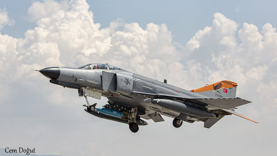
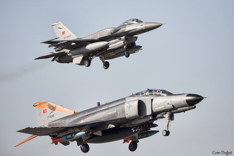
Our F-4E/2020 fighter jets, which have completed their 50th year in the inventory of our Turkish Air Force, performed the "Elephant Walk" on the runway and conducted a "Low Altitude Training Flight" in the valley, specially for the 50th year.
 
50 years! Well they've been service for a long time, how long before they're retired?
 
50 years! Well they've been service for a long time, how long before they're retired?
They're way past their retirement age, thank Erdogan, the Congress & the US Government for that.

As in the name: F-4E 2020 Terminator.

There's less than two dozen of them still active.
 
Is the Turkish aerospace industry being commissioned to do a total rebuild and upgrade of them?
There's nothing left to "rebuild and upgrade".

They're still kicking it though, nowadays they're mostly used for testing outsized air-launched payloads that the F-16s simply can't haul.

Since they're sturdy, "truck-like" and not at all "gentle" unlike the F-16, they're the most beloved jet of the pilots from the 401st Test Squadron.

EXwR7WqXYAQ1DDr.jpg FOddx0MXMAQ-JWp.jpg_large.jpg
 
Last edited:
There's nothing left to "rebuild and upgrade".

So their airframes are too old? If that's the case there's something the British call refurbishment where the airframe is completely dismantled with ALL parts inspected, the fatigued parts identified and discarded before being replaced by new replacement parts then the airframe is rebuilt (The rebuild has the equivalent fatigue life of aircraft that has flown a few hundred hours).

Since they're "truck-like" and not at all "gentle" unlike the F-16, they're the most beloved jet of the pilots from the 401st Test Squadron.

So they love their "Manly" F-4s;).
 
So their airframes are too old? If that's the case there's something the British call refurbishment where the airframe is completely dismantled with ALL parts inspected, the fatigued parts identified and discarded before being replaced by new replacement parts then the airframe is rebuilt (The rebuild has the equivalent fatigue life of aircraft that has flown a few hundred hours).
That was a sound investment for Turkey back when they were looking to upgrade to F-15Es in the 90s (and they went with the F-4 mod due to an earthquake that shook the budget) but not in the 2020s.

For more info on TurAF's history with the F-4:

https://www.defenceturkey.com/en/content/f-rf-4e-phantom-ii-in-the-turkish-airforce-3914

Anyway, I really gotta sleep... :)
 
So their airframes are too old? If that's the case there's something the British call refurbishment where the airframe is completely dismantled with ALL parts inspected, the fatigued parts identified and discarded before being replaced by new replacement parts then the airframe is rebuilt (The rebuild has the equivalent fatigue life of aircraft that has flown a few hundred hours).


So they love their "Manly" F-4s;).
you can "Phantom of Theseus" them as long as you are willing to fabricate replacement components
 
I'd actually suggest that car-makers would be better equipped to deal with stamping dies.

That's a very interesting point which I hadn't thought of.

Edit: Aside from the landing gear struts what else in the F-4's airframe uses forgings?
 
Last edited:
The F-4E should be able to land on an aircraft-carrier but could it be catapulted from one?
 
Not in the "as-delivered" Air Force configuration; the catapult bridle hooks and fittings had been deleted from the airplane.
 
the catapult bridle hooks and fittings had been deleted from the airplane.

That doesn't surprise me and IIRC the F-4E also had its' wing-folding hydraulics removed too (The wing-tips had to be manually folded and unfolded). I imagine though it wouldn't have taken much effort to add them back in.
 
The F-4E should be able to land on an aircraft-carrier but could it be catapulted from one?
USAF normally have weaker arresting hooks than USN aircraft, as the USAF's field arresting gear puts much less strain on the hook & airframe (decelerates the aircraft over a much longer distance).

While the USAF did delete some carrier equipment for its F-4s I don't see why they would have had the arresting hook & mount redesigned to lighten them - not much weight would be saved but the mod would cost a pretty penny.

The landing gear is also mostly the same - but they would have lower-pressure tires that would likely blow out in a carrier landing.
The AF tail hooks were the same as the Navy's. The late great Ed Rasimus in his many RAM posts and in his F-4 centric book, When Thunder Rolled, recounted how it was routine for AF Phantoms to take the barriers to avoid loss of control on wet runways in SEA. One reason this was routine is because it was the same hook meant for a carrier and an AF barrier was far less stressful.
 
Periscope Films uploaded this late 60s McD F-4 promotional film:


Presented by McDonnell Douglas, "The Phantom II In Action", features footage of the F-4 Phantom II, a highly capable weapon system designed to deliver precise attacks under a wide range of conditions. It excels in performance, having set 15 world records, including in speed, maneuverability, and climb rate. Demonstrating its effectiveness, the Phantom successfully intercepted and destroyed a Q2C Firebee drone during a 1963 test by firing four Sparrow 3 missiles, all of which hit the target with pinpoint accuracy. This showcased the Phantom's exceptional ability to perform precise weapon deliveries, establishing it as a reliable and lethal weapon system for the U.S. Navy, capable of operating effectively in both high and low-altitude environments.
00:00 - Introduction to the requirements of a weapon system: A weapon system must deliver weapons accurately on target in all weather conditions, at various altitudes and ranges, and with precise tracking, day or night. It needs to carry destructive ordinance and employ effective attack systems.
0:48 - Introduction of the Phantom 2: The Phantom 2, developed by McDonnell, is introduced as an aircraft that meets these stringent performance standards. Its performance has been repeatedly demonstrated and recognized through world records.
1:27 - World record achievements: The Phantom 2 set 15 world records, several of which remain unbroken. These records highlight its speed, maneuverability, rate of climb, and high-altitude capabilities. The Phantom excels in both high-altitude and low-altitude, high-stress environments.
2:01 - Weapon delivery demonstration: The Phantom’s weapon delivery abilities were demonstrated during a 1963 test where four Phantoms intercepted a Q2C Firebee drone flying over the Pacific at 460 mph. The mission highlighted the precision and effectiveness of the Phantom.
3:00 - Successful missile launch: During the demonstration, four Sparrow 3 missiles were fired with remarkable accuracy, all of them striking the target, causing the Firebee drone to crash into the sea.
3:29 - Conclusion: The performance of the Phantom 2, especially in terms of accuracy and missile targeting, proves it as a reliable and lethal weapon system, capable of executing pinpoint attacks with exceptional precision.
 
USAF normally have weaker arresting hooks than USN aircraft, as the USAF's field arresting gear puts much less strain on the hook & airframe (decelerates the aircraft over a much longer distance).

While the USAF did delete some carrier equipment for its F-4s I don't see why they would have had the arresting hook & mount redesigned to lighten them - not much weight would be saved but the mod would cost a pretty penny.

The landing gear is also mostly the same - but they would have lower-pressure tires that would likely blow out in a carrier landing.
Blackbat -

Howdy !

To my knowledge, the Navy F-4s featured smaller width tires/wheels than did the USAF
F-4 models. This required a “domed “ ( fiberglass ? ) panel to be added to the top of both wings above each Main Landing Gear wheel well…. to allow the fatter wheels/tires to fit the USAF planes; per that Service’ desires.


With regards,
357Mag
 
That's a very interesting point which I hadn't thought of.

Edit: Aside from the landing gear struts what else in the F-4's airframe uses forgings?
NM -

Howdy !

As regards forging use in F-4s…

Beyond what Scott Kenny said, I speculate the “ bulkhead “ located at the engine inlets
“ bellmouth “ was a large forging ( as another example ). Also, any wing-to-fuselage load carrying attach points.


With regards,
357Mag
 
Beyond what Scott Kenny said, I speculate the “ bulkhead “ located at the engine inlets
“ bellmouth “ was a large forging ( as another example ). Also, any wing-to-fuselage load carrying attach points.

What about the titanium-alloy firewall between the two J-79 engines?
 
What about the titanium-alloy firewall between the two J-79 engines?
Nausea -

Howdy !

The F-4’s central engine bay-separating “ keel “ had a flat… vertically-oriented center
“ sheet “ of titanium; to which were attached vertically-oriented stiffening ribs ( also titanium….if memory serves ).

From my recollection, there wasn’t a whole bunch of stuff mounted to it other than things like fire warning system wiring and associated metallic “ fire loops “. And, the left engine bay upper side of the keel mounted the large diameter bleed air ducting going Fwd to the Cabin & Equipment Environmental Control Systems. There was a hole in the keel that allowed bleed air ducting from the Rt engine to merge with the Left engine bleed air; trunked then to the single large diameter bleed air duct ( mentioned above ).

At one point… that large central ( hot ) bleed air duct was routed right beneath Fwd fuselage tankage. To work on ( replace ) the fwd “ Y” section of duct that split the bleed air going to the Rt and Lt ECS pac’s, a Fwd Fuel Cell rubber “ bladder “ had to be removed after all internal tubing/valves/pumps removed; then the hefty bladder compacted ( folded ) enough & strapped to allow hoisting it out through the overhead Fuel tank bay’ door. Then… the metal floor plate at the bottom of the tank bay was removed ( multiple 3/8” head bolts )… and THEN … one had gained access to the central bleed a duct. The clearances were tight, and the duct was enclosed within a
5-piece Quilted metal foil insulation blanket; which had insulating fibres contained within the outer foil walls. While the blankets were worked from the bottom via access in lower Door 22… the duct and associated clamps theirselves were worked from inside the Fuel cell bay. The individual foil blankets were woven together, using .032” safety wire…. woven in a cross hatch pattern like your shoe laces; by routing the wire around metal button heads attached to the foil. Too much tension applied, and you could pull out the buttons. And then…. Start the tedious blanket installation process all over again!

But… I digress !

With regards,
357Mag
 
What about the titanium-alloy firewall between the two J-79 engines?
NMaude -

Howdy !

Please excuse the incorrect auto-spell function of the previous response….
that spelled your moniker wrong . I did not catch the error, until just now.


With regards,
357Mag
 
Blackbat -

Howdy !

To my knowledge, the Navy F-4s featured smaller width tires/wheels than did the USAF
F-4 models. This required a “domed “ ( fiberglass ? ) panel to be added to the top of both wings above each Main Landing Gear wheel well…. to allow the fatter wheels/tires to fit the USAF planes; per that Service’ desires.


With regards,
357Mag

Yes - and those smaller USN/USMC tires had higher internal pressures specifically for the more-demanding carrier landings.

The wider lower-pressure tires the USAF liked did give more traction on plain asphalt or concrete runways (and less sinking into weak surfaces) - the non-skid deck coatings of carriers provided more traction than normal runways.
All -

As regards the F-4’s MLG tires ability to interface with the runway surface…..

The USAF/ Air National Guard / USAF reserve F-4s were outfitted with an “ anti-skid “ system. There was a skid sensor located within the MLG axels, and a 2 wire harness that routed the skid signal to the “ Anti-Skid “ control box.

Crew Chiefs would pressure wash their aircraft, giving little or no concern to the potential of water encroachment into the anti skid “ harnesses “ , especially water driven under pressure into the rubberized materiel inside the “ Canon plug “ back shell of the connector to the anti- skid sensors.

As a result….anti-skid fault lights were frequently encountered, especially before flight.
Having the anti-skid fault light constantly illuminated resulted in the aircraft being grounded; preventing flight. There were way too frequent occupancies of these lights, and something had to be done….

Aircraft Electricians were tasked with all Anti-skid system troubleshooting, and usually also had to provide an enduring “ fix “ for all discrepancies. We found out that the crew chiefs did use wheel covers when power washing their aircraft, however…. these were old covers that had been used on the unit’s former fleet of F-100s. The covers did not fit well, were well worn; and did not cover all areas they needed to.

We pressed to have new wheel covers made by the Parachute Shop. These helped reduce water encroachment into the Anti-skid connector plugs, but fault lights were illumination events were still occurring at an excessive level. Aircraft availability rates were still being negatively impacted.

The Electric Shop on their own initiative, made up new anti-skid harness “ pigtails “, that featured epoxy putty cured in the outer end of the Canon plug “ back shells “.
These pigtails were long enough to replace the defective wiring harness on the jet, and ran from the center of the MLG axels, up the MLG struts, and were the spliced-in new up inside the wheel well Anti-skid wiring harness. THIS was at last, the enduring fix we were asking for !

As an aside, let’s remember…. “ F-4 Anti-skid did not apply the brakes….it interrupted the brake application signal to the Brake Control box / valve when a skid was detected. Thereafter, when the skid danger had been mitigated…. the anti-skid “ system “ allowed the brake application signal to return to the Brake Control system; for re-application of the desired braking.


With regards,
357Mag
 
As an aside, let’s remember…. “ F-4 Anti-skid did not apply the brakes….it interrupted the brake application signal to the Brake Control box / valve when a skid was detected. Thereafter, when the skid danger had been mitigated…. the anti-skid “ system “ allowed the brake application signal to return to the Brake Control system; for re-application of the desired braking.
Side note, that's basically how all ABS systems work, by interrupting the source of pressure to the brakes and letting the wheel speed back up. It's rather violent on my 1994 Jeep Cherokee, feels like I'm standing on an air hammer.
 
Side note, that's basically how all ABS systems work, by interrupting the source of pressure to the brakes and letting the wheel speed back up. It's rather violent on my 1994 Jeep Cherokee, feels like I'm standing on an air hammer.
Scotty-

Howdy !

A bit after our unit converted from flying F-4Es to F-16C/D Block 32, we became away of pilot’s complaining about performance of the Anti-skid system; something to the effect of…. the “ Anti-skid “ system was keeping the planes from braking adequately; in a variety of scenarios. We learned that apparently, the performance complaints were wide spread, across many USAF and Air National Guard units.

At length, Units were informed that the Air ForceLogistics Command was sending around a representative to the various bases; to specifically inform and educate unit pilots of THE proper method the ALC had determined all F-16 pilots should perform Braking.

That recommendation was, quite simply:
NO matter what the runway and weather condition….
Press down on the top of the rudder pedals fully enough to ask the Brake / Anti-skid system for MAXIMUM braking….irregardless of what the prevailing weather & runways conditions are.

Our pilots were somewhat reticent to apply the ( basically mandated ) identified braking procedure, and there was no active oversight to force pilot’s to follow the ALC procedure.

As time went by, all the excitement sorta died down. I DO recall being called up to QA, to help debrief a pilot; after he had completed a “ Functional Check Flight “ on a jet.
Once he got done stating that the “ Anti-skid “ system was making the jet’s braking cycle on/off, I immediately responded in front of all present…. “ Good… that is what it’s supposed to do “ !

The QA rep started right in on challenging my assertion, and I reminded all that the correct Braking procedure was to fully mash down on the brake pedals. The Pilot wanted to argue that use of the ALC procedure was more of a suggestion than a mandate. I pointed out that on dry pavement like the runway was when he landed, full Brake application “ like I was sure he performed “ would result in Brake application cycling…. Just as he described. Both the pilot and QA appeared non-pluses, and I walked out.


With regards,
357Mag
 

Similar threads

Back
Top Bottom