- Joined
- 25 June 2009
- Messages
- 14,245
- Reaction score
- 4,571
I really thought we already had a topic on this one, but after several unfruitful search attempts I guess I must have been wrong.
Useful sources:
http://www.dtic.mil/dtic/tr/fulltext/u2/a263514.pdf
http://www.dtic.mil/dtic/tr/fulltext/u2/a068345.pdf
http://www.dtic.mil/dtic/tr/fulltext/u2/a068346.pdf
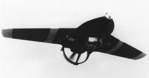
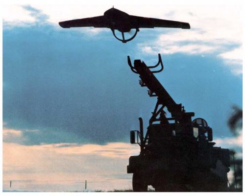
Development of the U. S. Army Aquila (XMQM-105) began as a program to provide a UAV technology demonstrator. The air vehicle was developed under Lockheed's proposal, Remotely Piloted Vehicle System Technology Demonstrator Program (RPV-STD) for the U. S. Army, LMSC-D056091, 30 August 1974. The Aquila was developed for a principal mission of surveillance, target acquisition, fire adjustment, and damage assessment in support of Army artillery and ground forces. The vehicle is configured as a flying-wing aircraft with a wing span of 12 feet, 3 inches.
Before final production ended, the Aquila had seen many modifications to its structural and aerodynamic design. The Aquila airframe obtained by the Naval Postgraduate School is from the manufacture period between December 1974 to December 1977.
The significant features of the vehicle are:
• Swept wing.
• Shrouded pusher propeller.
• Removable wings for storage.
• Lightweight Kevlar® construction.
• Pneumatic rail launch.
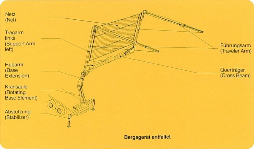
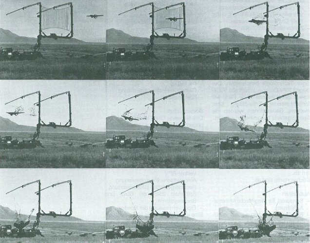
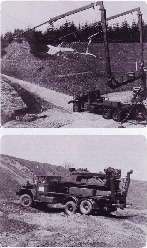
• Vertical barrier net recovery.
The airframe is constructed of advanced composite materials. Structural strength and stiffness are provided through the use of composite sandwich construction. This construction technique reduces the need and extra weight associated with the conventional method of rib, bulkhead, and stringer structural design. The fuselage is designed of varying elliptical cross section which is faired very smoothly into the 280 swept wing to provide a very low radar cross section. Power is provided with an aft-mounted ducted propeller. The propeller shroud provides increased safety to operating personnel during ground launch procedures and protection to the propeller during net capture, while also providing directional and longitudinal stability. Flight control was accomplished through movable elevons on the wing. A major downfall was that the vehicle required a large crew of ground personal and a considerable inventory of equipment for launch, control, and recovery.
Useful sources:
http://www.dtic.mil/dtic/tr/fulltext/u2/a263514.pdf
http://www.dtic.mil/dtic/tr/fulltext/u2/a068345.pdf
http://www.dtic.mil/dtic/tr/fulltext/u2/a068346.pdf
Attachments
-
 Lockheed MQM-105A Aquila.jpg79.8 KB · Views: 467
 -
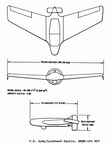 Lockheed XMQ-105 Aquila RPV.gif20.5 KB · Views: 437
 -
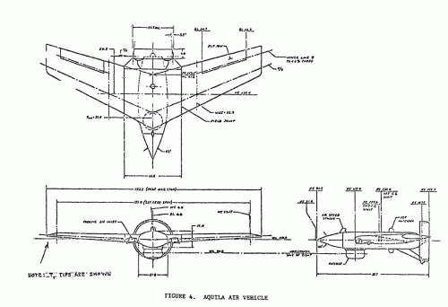 Lockheed MQM-105A Aquila Air Vehicle.gif38.3 KB · Views: 419
 -
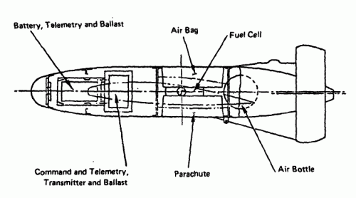 Lockheed MQM-105A Aquila Recovery System Installation.gif14.3 KB · Views: 393
 -
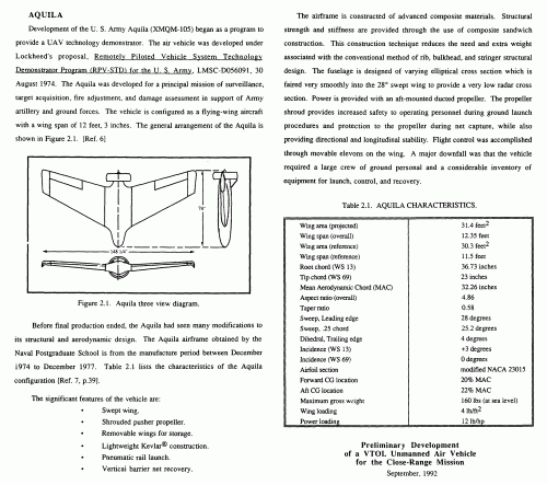 description.gif231.5 KB · Views: 399
 -
 aquila_01.jpg33.8 KB · Views: 97

