- Joined
- 1 April 2006
- Messages
- 11,053
- Reaction score
- 8,511
ASPEN BACKGROUND
In the 1950s and 1960s, many potential uses of nuclear power were explored, such as NTRs. An NTR uses a nuclear reactor to heat a working fluid, such as hydrogen, and exhaust this fluid in a nozzle for thrust. Many studies of this technology were conducted, and prototypes were built and tested.
ASPEN (AerospacePlane With Nuclear Engines) was originally a classified study conducted at the Los Alamos Scientific Laboratory in 1961 by R. W. Bussard. It was an SSTO vehicle that used turbojets and ramjets followed by an NTR to provide the final boost into orbit. The study was declassified and approved for public release in 1995.
ASPEN Reactor Shielding
Shielding is a major concern for nuclear reactors, and is of particular interest in aerospace applications due to the large weight. In a crewed vehicle, the radiation dose must be limited to certain levels for
crew safety. Payloads may also have shielding requirements, but these are usually much less stringent and can usually be included in the payload design.
Terrestrial reactors typically completely surround the reactor with several inches of lead and other shielding materials. In order to minimize the shielding weight for space applications, it is desirable to use a shadow shield, which only shields radiation in one direction. This technique places a shield between the reactor and the crew, but does not completely surround the reactor. With this configuration, the portion of the vehicle aft of the shield would become radioactive due to the neutron flux while the reactor is at power. The effect of this on operations was not analyzed in this study.
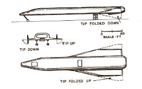
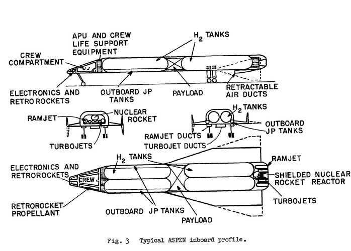
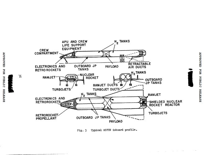
ASPEN Configuration ASPEN is a traditional wing-body vehicle with a high fineness ratio. Small turbojet and ramjet inlets are integrated onto the underside of the fuselage. The NTR engines are placed on the aft base area of the fuselage. An internal payload bay is provided between large internal hydrogen (LH2) tanks. A crew cabin is placed near the nose of the vehicle. ASPEN takes off and lands horizontally on retractable landing gear.
ASPEN Configuration
ASPEN is a traditional wing-body vehicle with a high fineness ratio. Small turbojet and ramjet inlets are integrated onto the underside of the fuselage. The NTR engines are placed on the aft base area of the
fuselage. An internal payload bay is provided between large internal hydrogen (LH2) tanks. A crew cabin is placed near the nose of the vehicle. ASPEN takes off and lands horizontally on retractable landing gear.
ASPEN Mission
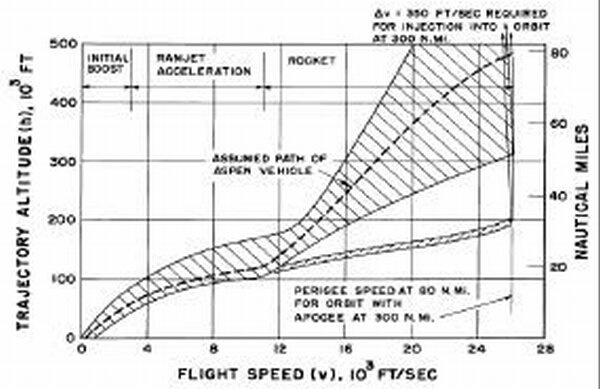
The original ASPEN vehicle used LH2 turbojets for take-off and to accelerate to Mach 2.5 at 60,000 ft. At this point, the subsonic combustion ramjet engines would accelerate it to Mach 11 at 120,000 ft. (Note: contemporary wisdom would include a switch to supersonic combustion scramjets above Mach 5 or 6. Conceptual design tools now available were not able to duplicate the ASPEN ramjet performance to Mach
11.). From Mach 11, the NTR would provide the final acceleration to put the vehicle in an orbit with perigee of 80 nmi and apogee of 300 nmi. Radiation can scatter off the atmosphere and reach the crew even if
no direct path from the reactor to the crew is left unshielded. For this reason, an NTR powered vehicle should not bring the reactor up to full power until it is high in the atmosphere in order to reduce shielding requirements. Figure 3 shows the proposed trajectory for the original ASPEN vehicle. The flight corridor shown diverging below the main corridor above 12,000 ft/sec flight speed in Figure 3 was a proposed flight corridor for a NASP-like vehicle that accelerated to orbital velocity using only air-breathing engines. As the NASP program later showed, acceleration to Mach 25 using only air-breathing propulsion is now considered highly unlikely.
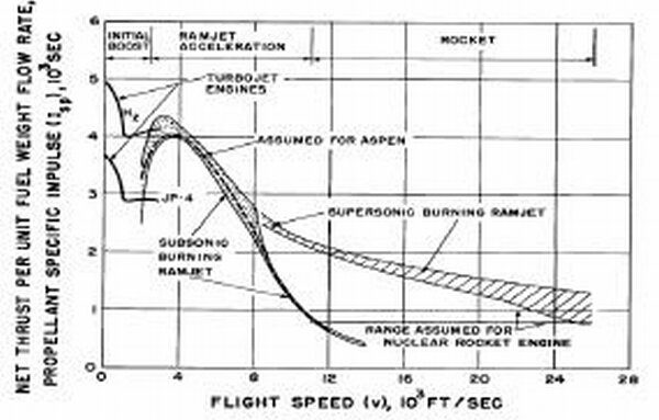
The Isp assumed for the original ASPEN vehicle is shown in Figure 4. The supersonic burning region shows the projected performance of a scramjet engine, but the ASPEN concept utilized subsonic combustion ramjets to Mach 11, as previously noted.
The thrust-to-weight and drag-to-thrust ratios from the original analysis are shown in Figure 5. The vehicle thrust-to-weight (T/W) is 0.3 at takeoff, which equates to 150,000 lbs. of turbojet thrust. At rocket
takeover, the T/W is 0.6 and the vehicle is about 82% of GLOW, which equates to about 245,000 lbs. of NTR thrust. Note that the predicted D/F of only 0.2 between Mach 6 and Mach 11 (thrust-to-drag ratio of
5) must be viewed with some degree of skepticism. Even well designed contemporary air-breathing RLV configurations are unable to achieve this level of acceleration at higher Mach numbers.
ASPEN Sizing Results
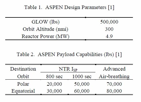
The ASPEN vehicle was designed to carry two passengers into orbit and remain in orbit for two days. The vehicle design parameters are listed in Table 1. The original payloads for the ASPEN vehicle are presented in Table 2. The vehicle was sized for a constant gross weight of 500,000 lb. The payload was allowed to vary in order to close the vehicle. As a baseline case, an NTR ISP of 800 sec was used. The report also considers an improvement in NTR ISP to 1000 sec. If the air-breathing engines could be replaced with “advanced chemical engines”, the orbital payload with an NTR ISP of 1000 sec increases to 80,000 lbs to a 300 nmi equatorial orbit. Payload mass fractions for the original ASPEN vehicle range from 6% - 16% for an equatorial orbit. By comparison, contemporary SSTO designs using traditional chemical rockets have propellant mass fractions of only 1% - 2%.
sources:
1). ASPEN - An AerospacePlane With Nuclear Engines
(Title Unclassified)
R. W. Bussard
LOS ALAMOS SCIENTIFIC LABORATORY OF THE UNIVERSITY OF CALIFORNIA LOS ALAMOS NEW MEXICO
REPORT WRITTEN May 1961
REPORT DISTRIBUTED: September 2’7, 1961
2). AIAA 2001-3514
ASPEN Revisited: The Challenge of Nuclear Propulsion for ETO
John E. Weglian, John R. Olds, Leland Marcus, James McIntire, Douglas Nelson
Attachments
-
 ASPEN.jpg35.6 KB · Views: 35
 -
 ASPEN-1.jpg82.3 KB · Views: 43
 -
 ASPEN-2.jpg172.4 KB · Views: 42
 -
 aspen-fig3.jpg110.8 KB · Views: 38
 -
 aspen-fig4.jpg105.8 KB · Views: 25
 -
 aspen-fig5.jpg109.3 KB · Views: 24
 -
 aspen-table1.jpg69.2 KB · Views: 27
 -
 Untitled.jpg130.8 KB · Views: 30
 -
 Untitled2.jpg200.9 KB · Views: 34
Last edited:
