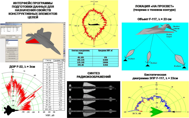
You know, I have the English version of the book where that chart came from.Again, what makes you think 4.5 gen fighter's real RCS is 1m2? And what does this 1m2 number exactly means? Average RCS or Peak low? In what aspect and/or sector? RCS isn't a constant number, it depends on angle and may change with every next impulse of radar, during countinuous scan.F-16 and F-18 with RCS about 1 m2
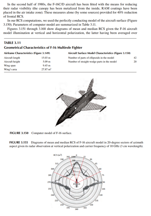
Firstly, as they admitted themselves, they use a perfectly conducting surface for their F-16 model while the real F-16 receive RAM and golden canopy from Have glass program
Secondly, judge by the number of parts in their model, they only make a very rough model of the F-16, that is hardly accurate
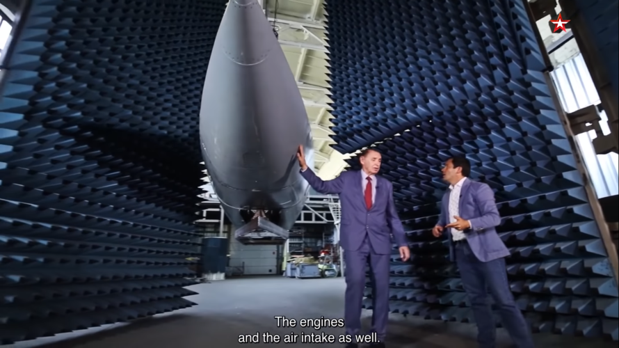
Thirdly, while their model suggest an F-16 with very high direct frontal RCS, when we go slightly off side between 15-65 degrees off side, the RCS value went below 1 m2 and even reach 0.1 m2 at some point. That pretty good for a perfectly conducting model.
I have also seen computer simulated radar scattering chart of stealth aircraft with very low value as well
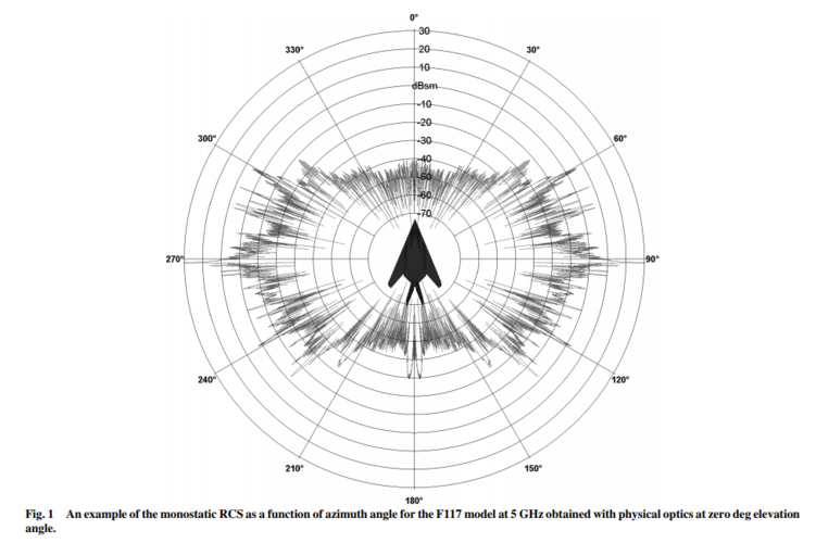
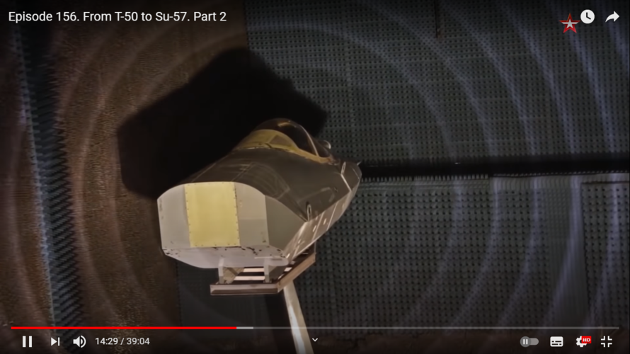
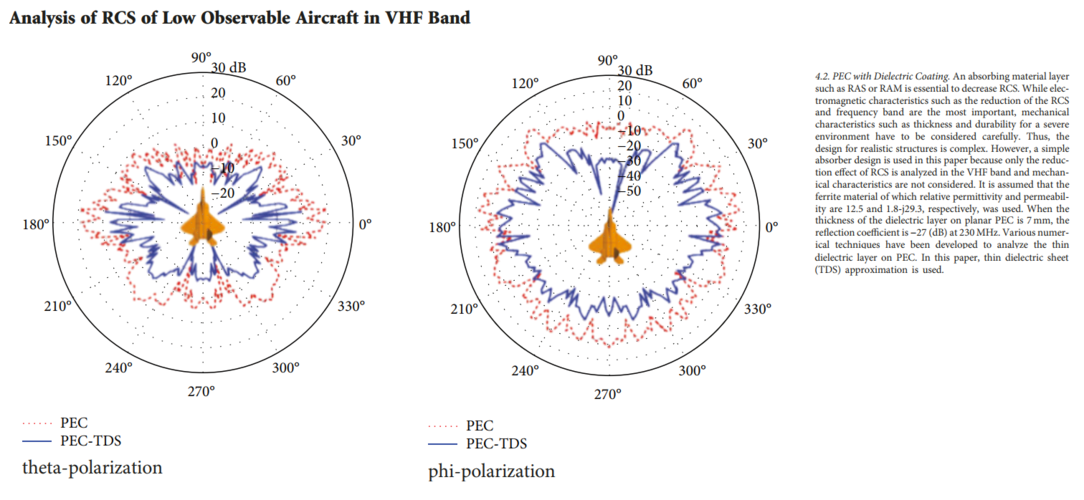
I didn't say they don't know how to make the chart correctly but there are things that will be impossible for them to model because they can't acquire the data to model them. For example: they can't know the absorbing capability of the RAM used on F-22 and F-35, and they can't know the exact inner radar absorbing structure without acquire the aircraft themselves. That why these radar scattering charts almost always assume a perfect conducting metal model. So if you see -10 dBsm or -20 dBsm on the chart, then the actual aircraft will have RCS less than that, but you can't know by how muchI dont think guys working on one of the main Air Defense Research Institutes don't know how to make RCS chart correctly. BTW, above the F-22 RCS chart you can see a screenshot for RAM characteristics adjustment.I have seen more than a dozen radar scattering charts like that even the one measured in anechoic chamber, they all have the same problems:
1- The aircraft surface are treated as pure metal with perfect reflecting capability, RAM (radar absorbing material) and RAS (radar absorbing structure) aren't taken into account.
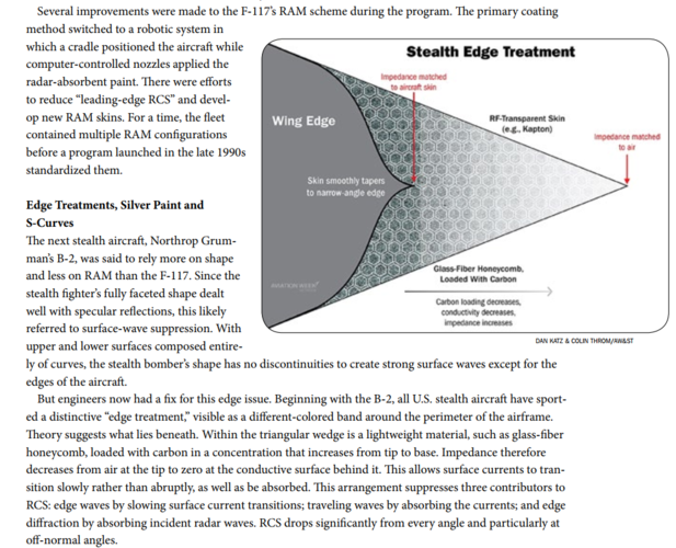
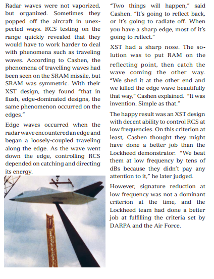
2- Leading edge and trailing edges treatment aren't taken into account
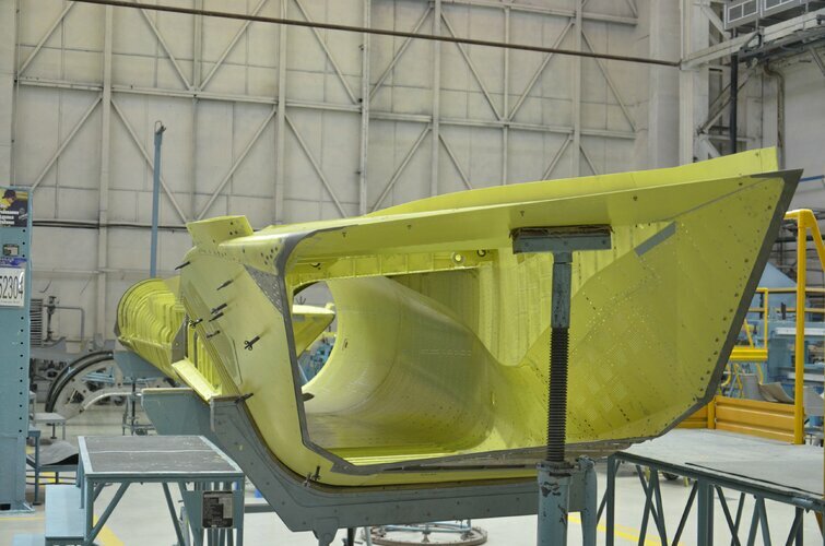
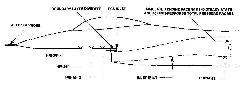
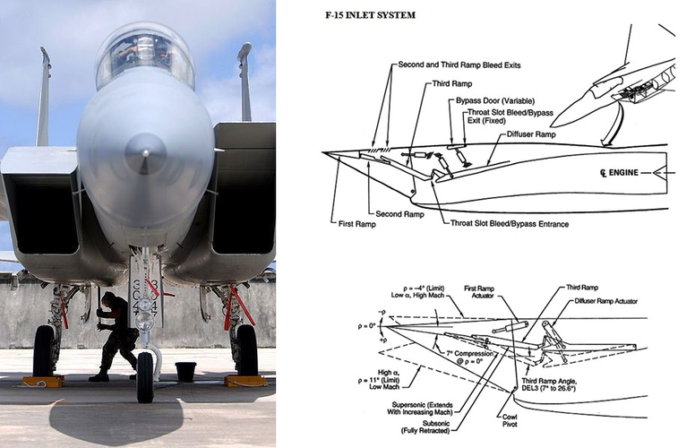
3- Many of them don't even model the inlet properly
For your information, of the two radar scattering chart I posted, the F-35 chart came from Nanjing university of aeronautics and astronautics and the F-117 charts came from Deutsche Bremen anechoic chamber, it isn't a simulation but measurement of a metal F-117 model.
And I'm not saying that you can't put an arbitrary absorbing value on the aircraft skin, I am saying that it won't be correct.
Last edited:

