I knew, I had seen it before, but couldn't find it by looking for Schütte-Lanz.
Found it in the end in "Die deutschen Flugboote" by Fred Gütschow, mentioned as the Hillmann Transozeanflugboot...
It was designed by Wilhelm Hillmann during 1925, former chief designer for Schütte-Lanz. That's certainly the reason for that designation, but Schütte-Lanz wasn't active then anymore in the aviation business.
Here's what is said in that book :
"
The project drawn up by Hillmann in 1925 envisaged to cross the Atlantic in several stages.
It was deliberately avoided designing a flying boat of enormous dimensions for the non-stop
flight betweenn Europe and the USA, as was done by several other designers in those years.
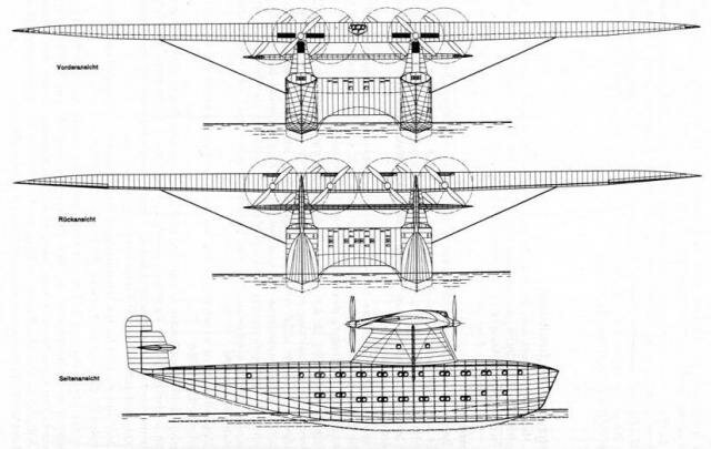
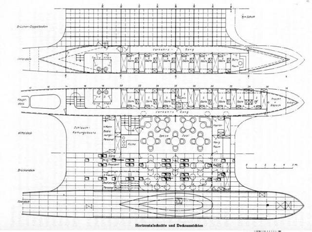
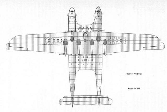
The Hillmann flying boat was designed with two hulls, connected by a bridge-like centre section,
housing the command centre at its front end ,which consisted of the captain's and navigation
rooms and the radio station. Adjacent to this was the dining and lounge area, as well as the
galley. In the rear part of the bridge, four inflatable dinghies for 15 people each were to
be stored. The number of passengers was set at 48, which was relatively modest compared to
other contemporary projects. They were to be accommodated in the two hulls in comfortable
cabins, which, due to the great height of the hulls were placed one above the other. The
remaining payload was also to be accommodated in the hulls.
For safety reasons, the hulls were heavily subdivided on about a third of the length and
fitted with a double bottom. The planing bottom had no steps, but there was the possibility
of providing themif necessary.
The continuous wing was supported by two towerlike pylons, protruding from the hulls, and a
strut for each outer. The center wing was to be sheet metal planked, whereas the outer wing
was fabric covered. The proposed propulsion system consisted of 6 engines of 1000 hp each,
which were to be positioned in the wing and accessible at all times. Two engines drove tractor
propellers, the other four engines drove pusher propellers. It was planned to use adjustable
propellers with a diameter of 5.3 metres.
The cruising speed was calculated as 225 km/h. Fuel for the engines was stored in fireproof
tanks in the outer wings. Between the rear hulls and protruding over the outer sides was the
tailplane, with adjustable angle of attack. The tailplane was constructed from spars and ribs
and metal-planked at the nose, the rest of the surface was was covered with fabric.
The vertical stabiliser was approximately the size of the outer parts of the tailplane and
resembled it in shape and construction. It was kept relatively small and was mainly intended
for corrections of course deviations, as tight turns were not expected. The tail unit was about
6 metres above the water and thus offered sufficiently protected against spray.
The main data for this project were:
span (over ailerons) 66.00 m
length 41.50 m
height (over prop tips) 12.00 m
height of wingtips over water 8.70 m
width of double hull boat 14.00 m
width of individual hull 3.00 m
span of tailplane 22.00.m
length of fin/rudder 5.40 m
Take-off weight with 48 passengers, baggage,
and freight 60 t
The designer didn't succeed in collecting sufficient funds for this project, but in 1930 there seemed
another chance, when Roald Amundsen und the then Danish counsel in Los Angeles, Captain Hakoon H. Hammer,
showed interest in the project, and founded the International Aero Ltd, Los Angeles, starting with
preparations for the construction. But with the world economic crisis the project was doomed then."
The drawing isn' any better, I think, sorry ...
(If you don't mind, I would change the title to "Hillmann ...")