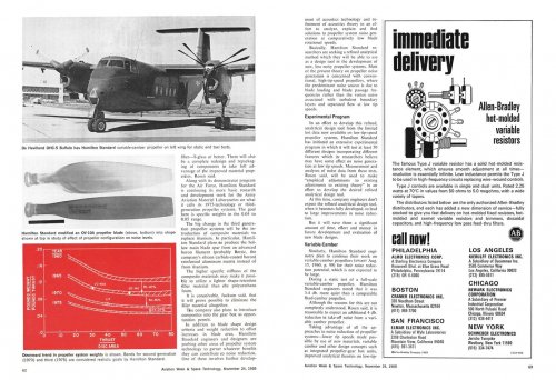
Hamilton Standard variable camber propeller

Caravellarella

ACCESS: Top Secret
Senior Member
Joined
30 November 2007
Messages
1,097
Reaction score
495
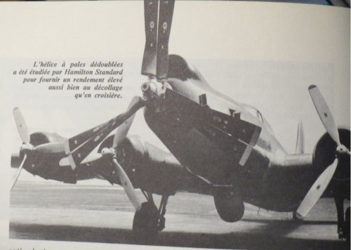
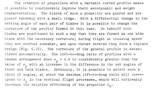
Dear Boys and Girls, here is an article in French about an unusual Hamilton-Standard variable-camber propellor "project" using two closely-coupled tandem propellor blades moving in the same rotation and in relation to each other to achieve a variable-camber aerofoil......

The article comes from the 24th September 1960 issue of Les Ailes......

Terry (Caravellarella)
 
I'd be concerned about 'chatter'...
 
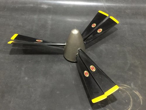
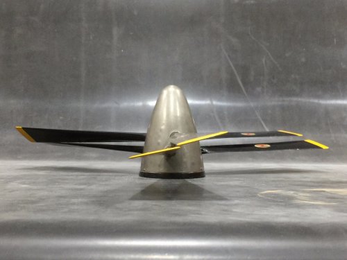
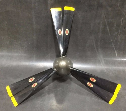
Here's an odd propeller display model currently for sale on eBay:


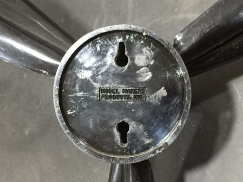
The model is described as having a 14" diameter, so it's probably not a component of an aircraft model but a representation of a Hamilton Standard product. It looks like a contra-rotating airscrew, but the blades all seem to be oriented to turn in the same direction. The hub also shows no sign of a division between contra-rotating parts.
Maybe it's just a contra-prop with a line decal missing from the hub and the blades attached incorrectly.
Any ideas?
 

Attachments

  • s-l1600aaaaaa.jpg
    s-l1600aaaaaa.jpg
    177.6 KB · Views: 739
  • s-l1600aaaaaaa.jpg
    s-l1600aaaaaaa.jpg
    196.2 KB · Views: 715
  • s-l1600aaaaaaaa.jpg
    s-l1600aaaaaaaa.jpg
    180.7 KB · Views: 678
  • s-l1600aaaaaaaaa.jpg
    s-l1600aaaaaaaaa.jpg
    221.4 KB · Views: 661
kitnut617 said:
could it be an experiment for a 'slotted' propeller blade ???

Yes. Or to put it another way, it's a way to make a thick, chord wise, blade, but also delay flow separation, since if it was a single blade with that much chord, of the two blades together, you would get a lot of flow separation. The slot re-energizes the flow, making it more efficient. At least in theory, anyway. They may have found they could get a blade 3/4 the chord of the two together that had close to the same performance at less cost. It would be interesting to see the results of these tests and the possible program application.
 
Would such a device have to be optimized for a relatively narrow set of flight conditions? The model suggests that the blade pitch can be varied, but any adjustment would alter the slot.
Also, wouldn't blade-to-blade contact be a worry with this configuration? Preventing this is apparently one of the challenges of designing large turbofan fan stages.
 
Sundog said:
kitnut617 said:
could it be an experiment for a 'slotted' propeller blade ???

Yes. Or to put it another way, it's a way to make a thick, chord wise, blade, but also delay flow separation, since if it was a single blade with that much chord, of the two blades together, you would get a lot of flow separation. The slot re-energizes the flow, making it more efficient. At least in theory, anyway. They may have found they could get a blade 3/4 the chord of the two together that had close to the same performance at less cost. It would be interesting to see the results of these tests and the possible program application.

Kind of a propeller blade with a Fowler flap :) There's a similar solution on the Russian AL-31F fighter engine 4th stage fan stator (more flow turning and hence pressure rise without separation).

EDIT: Would this topic perhaps be more appropriately moved to the propulsion section?


Indeed !
;)
 
taildragger said:
Would such a device have to be optimized for a relatively narrow set of flight conditions? The model suggests that the blade pitch can be varied, but any adjustment would alter the slot.
Also, wouldn't blade-to-blade contact be a worry with this configuration? Preventing this is apparently one of the challenges of designing large turbofan fan stages.

Hi !

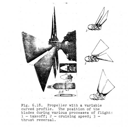
A picture of a real propeller with "double blade". I found that in my old book "L'aviation d'aujourd'hui" by Jacques Lachnitt - Librairie Larousse - 1968. It was a solution of "variable curvature" for turboengine propellers because at that time the variation of pitch was insufficient between high and low speed (it's clear ? ???) ...

Tonton
 

Attachments

  • IMG_4033.JPG
    IMG_4033.JPG
    225.1 KB · Views: 608
My guess is that the model and the installation illustrated above represent proof-of-concept hardware utilizing off-the-shelf components rather than a product. I'd think that a design intended for service would place each blade pair on a common pivot so that pitch could be varied independently of the slot configuration.
It's probably better for aircraft aesthetics that this idea didn't work out.
 
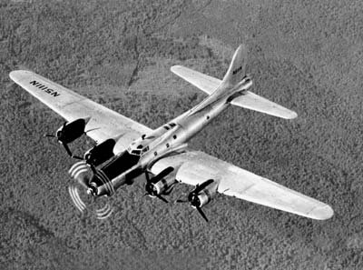
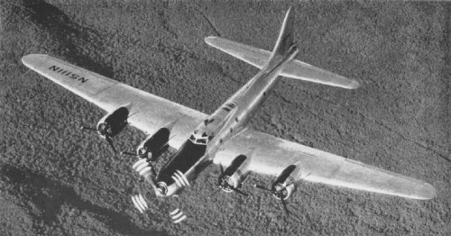
You can certainly see the size of it in that photo of Tonton's, it's fitted to the nose of a B-17

EDIT:

I would guess this is the same aircraft with the same propeller in flight (photos found on the internet, no idea who's they are)
 

Attachments

  • 5 engined B-17.jpg
    5 engined B-17.jpg
    27.4 KB · Views: 116
  • 5 engined B-17 test bed.jpg
    5 engined B-17 test bed.jpg
    144.2 KB · Views: 109
I think we can rule out a contraprop based on blade clearance.
 
kitnut617 said:
I would guess this is the same aircraft with the same propeller in flight
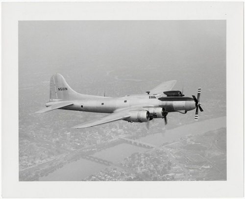
Nope. See attached photo of Pratt & Whitney's N5111N with the XT-34 turboprop feathered.

It may well be another of the JB-17 testbeds, though. Just not this one. IIRC there were three JB-17 conversions.
 

Attachments

  • US B-17 testbed w 5 engines Boeing Model 299-Z N5111N Pratt & Whitney test XT-34 turboprop.jpg
    US B-17 testbed w 5 engines Boeing Model 299-Z N5111N Pratt & Whitney test XT-34 turboprop.jpg
    51.9 KB · Views: 130
Orionblamblam said:

Thank you for these explanations :-* ! It had been more than 40 years since this strange thing titillated me the spirit in a hidden recess of my (young) brain ;) !
 
i suggest renaming the thread something like "Hamilton Standard variable camber propeller" or something to that effect.
 
FWIW, in urban mobility circles there is a resurgence of interest in something very similar, the stacked coaxial propeller. There is no variable pitch, but it does have two rows of co-rotating propellers not uniformly spaced.
For example you could have two rows of three bladed props, with the rear row being phased only 10 degrees behind the front one.
 
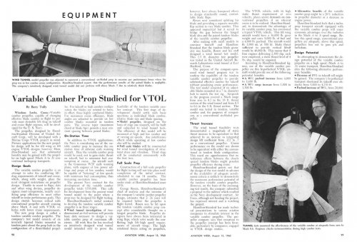
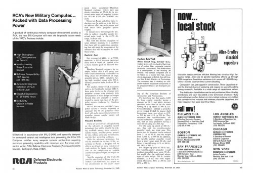
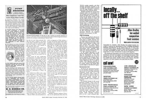
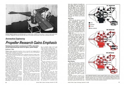
The work apparently continued for some years. From 1969:
 

Attachments

  • av week 1969-11-24 hamilton standard prop d.jpg
    av week 1969-11-24 hamilton standard prop d.jpg
    251.4 KB · Views: 74
  • av week 1969-11-24 hamilton standard prop c.jpg
    av week 1969-11-24 hamilton standard prop c.jpg
    248.4 KB · Views: 101
  • av week 1969-11-24 hamilton standard prop b.jpg
    av week 1969-11-24 hamilton standard prop b.jpg
    323.3 KB · Views: 111
  • av week 1969-11-24 hamilton standard prop a.jpg
    av week 1969-11-24 hamilton standard prop a.jpg
    267.2 KB · Views: 117
Found on AEHS website . . .

'The Hamilton Standard Variable Camber Propeller'


George Rosen was a Massachusetts Institute of Technology (MIT) graduate aeronautical engineer, class of 1937,who went to directly to work for Hamilton Standard as their first propeller aerodynamicist. George had long and distinguished career at Hamilton Standard, winning the United Aircraft Mead Medal in 1961 for the variable camber propeller and the Goddard Award from the American Institute of Aeronautics and Astronautics (AIAA) in 1975 for his many contributions to the turbine propeller. Rosen retired as Chief of Propeller Research and Development in 1977after forty years of service that spanned the heyday of the propeller. He was also a great patron of the arts and an accomplished sculptor late in his life.

Propeller design is typically optimized for a specific phase of flight, most often, efficiency in high speed cruise. One of the ongoing challenges of propeller propulsion is to provide the ability for high thrust for take-off with high thrust but low drag for cruise flight. Highly cambered propellers generate tremendous thrust at low airspeeds, but are draggy and thus inefficient in the high speed flight regime. Very thin propeller blades work well at high speed cruise, but have reduced thrust profiles at low airspeeds such as take-off. Variable pitch, constant speed propellers address this challenge quite well as long as runways are sufficiently long. But what about optimizing performance for missions that require short take-off and landing (STOL) or vertical take-off and landing (VTOL)?

George Rosen conceptualized an engineering approach to this “high thrust at low airspeed but efficient cruise" requirement with the variable camber (VC) propeller. His idea was to use two rows of propeller blades on the same single-rotation hub. The aft propeller disc would be displaced axially behind the fore prop disc, and the blades themselves would be offset by 25°between the rows. The pitch of each disc (row) of propeller blades could be adjusted independently of each other. (Fig. 6) This allowed the trailing blade to perform essentially as a slotted flap to the leading blade. George Rosen submitted a patent application for his invention on 19 December1958 and was granted US Patent 2,982,361 on 2 May 1961.

[..]

References
Thrusting Forward: A History of the Propeller, by George Rosen with Charles A. Azenis, published by the Hamilton Standard Division of United Technologies Corporation, 1984.
Variable Camber Blading, US Patent 2,982,361 , granted May 2, 1961, to George Rosen, assignor to Untied Aircraft Corporation.
Two Part Pitch Changing Mechanism, US Patent 3,163,231, granted Dec. 29, 1964, to Phillip E. Barnes, Seppo J. Viikinsalo, and Richard B. Pitbladdo, assignors to United Aircraft Corporation.
“Propeller Integral Gearbox 73EGB1 and Propeller Variable Camber Model VC86260 Flight Test Report”, Report HSER 4076 , Bureau of Naval Weapons Contracts NOw-64-0635-di and NOw-65-0533-d, 30 June 1966.
Variable Camber Prop Studied for VTOL by Barry Tully, Aviation Week , 15 August 1960, pages 98, 99, and 101.
Propeller Research Gains Emphasis by Michael L. Yaffee, Aviation Week and Space Technology , 24 November 1969, pages 56, 57,62,63,64.
Advertisement by United Aircraft International, Flight International , 30 April 1964, page 4.
Obituary for George Rosen, Hartford Courant, 16 June 2004.
"Unusual Propellers" by John Leonard, Rolls-Royce Heritage Trust Allison Branch Newsletter , December 2010.
"Next Generation V/STOL Propellers" by George Rosen and William M. Adamson, SAE Transactions Vol. 77, Sec. 2, paper 680248-68434, pages 893-905, 1968.
Advanced Propeller Concepts ... Developed Today (Windsor Locks, CT: Hamilton Standard, 1965).

cheers,
Robin.
 

Attachments

  • HamStdVC.pdf
    859 KB · Views: 8
Last edited by a moderator:
I seem to remember one of the full-sized variable-camber propellers hanging on a wall in Hamilton's test area when I worked there, these many years ago.
 

Similar threads

Please donate to support the forum.

Back
Top Bottom