Graf Zeppelin Bombentorpedo
The concept WLK (Wasserlaufkoerper) was proposed in the summer of 1941 for air-dropped underwater bombs.
In the spring 1943 a new type of low-cost anti-ship bomb was developed under the codename BT.
The weapon was designed by Dr. Benecke of FZG Research Establishment (Graf Zeppelin Forschungsanstalt-Stuttgart).
When compared with the standard Lufttorpedo LT F5b, the BT bomb had the advantage of being built with non-strategic materials (cast iron and steel plates) and half its weight was that of the warhead.
The construction of a 435 kg BT bomb required sixty man-hours compared to the 2,000 man-hours of one LT F5b, over 97 per cent reduced production time.
FZG proposed the manufacture of the new weapon in ten series weighing 220, 435, 780, 755, 1000, 1180, 1510 and 1923 kg.
During the Luftwaffe's standard torpedo launch, the aircraft had to fly at very low altitude and low speed, exposing itself to attacks by enemy anti-aircraft artillery and naval fighters.
The BT bomb could be launched from a schnellbomber diving from 1,500 meters and enter the water just short of the target.
To prevent it from going too deep before detonation, a relatively flat angle of entry was necessary.
Scale model tests carried out by the LFA Institute at Niedersonthofener See mathematically proved that a BT weighing 1,000, with an impact angle of 30º, would reach its detonation depth under the keel of the enemy ship after traveling 100 meters underwater, propelled by its remaining kinetic energy.
The slender conical warhead would explode by means of a magnetic proximity fuse.
The LFA determined that the required accuracy could not be achieved using the Revi aiming system designed for torpedo launching.
During July-August 1944 a number of launch tests were carried with considerable success at TWP (Gotenhafen-Hexengrund Torpedo Waffenprufplatz).
Focke-Wulf Fw 190 carrier aircraft equipped with FuG 101 radio altimeters and TSA-2A dive bomb release computers were used.
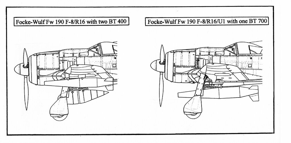
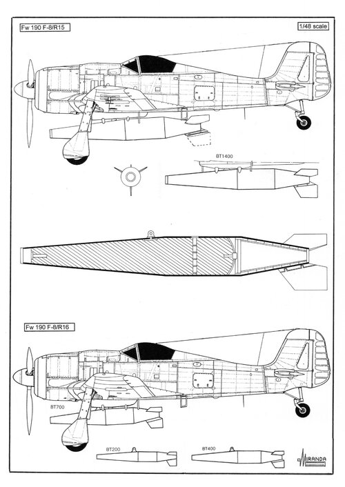
One Fw 190 F-8/R16 was used to test seven BT bombs of the 435 kg class mounted in two ETC 503 underwing racks by means of a single suspension eye/bolt.
One Fw 190 F-8/R16/U1 was used to test BT bombs of the 780 kg class mounted in one ETC 501 ventral rack.
One Fw 190 F-8/R16/U2 was used to test BT bombs of the 1,510 kg class mounted in one ETC 502 ventral rack.
In April 1945 the III./KG 200 had 24 serviceable BT carriers.
These high-velocity weapons were released from the carrier plane automatically (at the correct point in the dive towards the target) by means of the Zeiss TSA (Tiefsturzanlage) bombsight computer coupled with the radio-altimeter. TSA automatically compensated for the target speed and the time of fall of the BT.
By 1944 the OKL had decided to produce ten models of BT bombs: BT200 C1, BT200 C2, BT400 C1, BT400 C2, BT700 C1, BT700 C2, BT 1000, BT 1000 RS, BT 1400 and BT 1850 but only a few prototypes were made, between November 1944 and December 1945, in Trippelwerke-Elsass facilities.
“C1” indicates tail assembly welded to the baseplate of warhead, “C2” indicates tail assembly screwed.
Intended mass production at Blohm und Voss-Menibum works was cancelled in February 1945.
One conventional bomb fitted with ojival nose will ricochet off water when it strikes at a flat angle.
Extensive tests about the water-entry of BT conical warheads were conducted by Professors Madelung and Wagner at the Preussische Versuchsanstalt fur Wasserbau und Schisbau Research Establishment.
The rectilinear course below the water surface, without noticeable deflection, was achieved by nose mounted cavitation devices (onion, spray ring, semi-sphere and spoiler plate) called separation edges.
In some of the heavier bombs as the BT 1400 the plate baffle was installed at 10° inclination in order to curve the underwater trajectory slightly upwards because during the tests this type of pump showed a tendency to sink more quickly than expected.
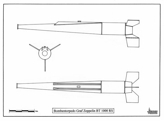
Two dorsal ridges and one baffle plate were installed on the BT 1000 RS with the intention of simultaneously creating drag and longitudinal stability, but its water entry speed of 267 m/sec was considered excessive.
The triple tailfins, mounted offset 120º to each other, provided flight stability for the bomb. The tail assembly was designed to separate upon striking the water and the warhead continues towards the target.
In the models BT 200, BT 400 and BT 700 the tail cone was held in place by means of aluminum shear screws, in the heaviest BT’s the tail was jettisoned by means of explosive bolts. The detachment of the tail does not affect the water course.
Zeppelin proposed four types of fuses:
-Hydrostatic fuse Krupp Wasserdruckzünder Type 44 with 8-11 meters dept for detonation.
-Time fuse ZZ59 with 0.44 second delay time.
-Impact fuse ElAZ 28C with 0.12-0.18 second delay time.
-Magnetic proximity fuse Pi-MZ.
The one exception to the kinetic design was the BT 1000RS fitted with the Rheinmetall-Borsig rocket motor of the PC 1000RS armor piercing bomb. The rocket ignited by an CII electric fuse three seconds after release.
Proposed carrier planes
-BT 200: Focke-Wulf Fw 190 F-8/R16.
-BT 400: Focke-Wulf Fw 190 F-8/R16, Arado Ar 234 B-2.
-BT 700 C1: Focke-Wulf Fw 190 F-8/R16/U1, Focke-Wulf Fw 290, Messerschmitt Me 262 A-2a/U1.
-BT 700 C2: Blohm und Voss BV 40.
-BT 1000: Messerschmitt Me 163B, Messerschmitt Me 328A.
-BT 1400: Focke-Wulf Fw 190 F-8/R16/U2, Arado Ar 234 C-3.
Graf Zeppelin BT 200 technical data
Length: 2,395 mm, diameter: 300 mm, tailplane span: 560 mm, weight: 220 kg, warhead 105 kg of Hexanite, range (launched with 30º dive and 600 m height): 900m, estimated underwater course: 20 m.
Graf Zeppelin BT 400 C1 technical data
Length: 2,946 mm, diameter: 378 mm, tailplane span: 710 mm, weight: 435 kg, warhead 215 kg of Hexanite, estimated underwater course: 20 m.
Graf Zeppelin BT 700 C1 technical data
Length: 3,500 mm, diameter: 426 mm, tailplane span: 1,100 mm, weight: 780 kg, warhead 330 kg of Hexanite, estimated underwater course: 45-50 m.
Graf Zeppelin BT 700 C2 technical data
Length: 3,358 mm, diameter: 456 mm, tailplane span: 850 mm, weight: 755 kg, warhead 320 kg of Hexanite, estimated underwater course: 25 m.
Graf Zeppelin BT 1000 technical data
Length: 4,240 mm, diameter: 480 mm, tailplane span: 1,305 mm, weight: 1,000 kg, warhead 710 kg of Hexanite, range (launched with 20º dive and 400 m height): 450-500 m, estimated water entry speed: 160 m/sec.
Graf Zeppelin BT 1000RS technical data
Length: 4,896 mm, diameter: 480 mm, tailplane span: 1,224 mm, weight: 1,180 kg, warhead 710 kg of Hexanite, range (launched with 20º dive and 1,500 m height): 3,200 m, estimated water entry speed: 267 m/sec, power plant: one Rheinmetall-Borsig solid-propellant rocket motor rated at 5,850 kg peak thrust with 2.8 seconds life.
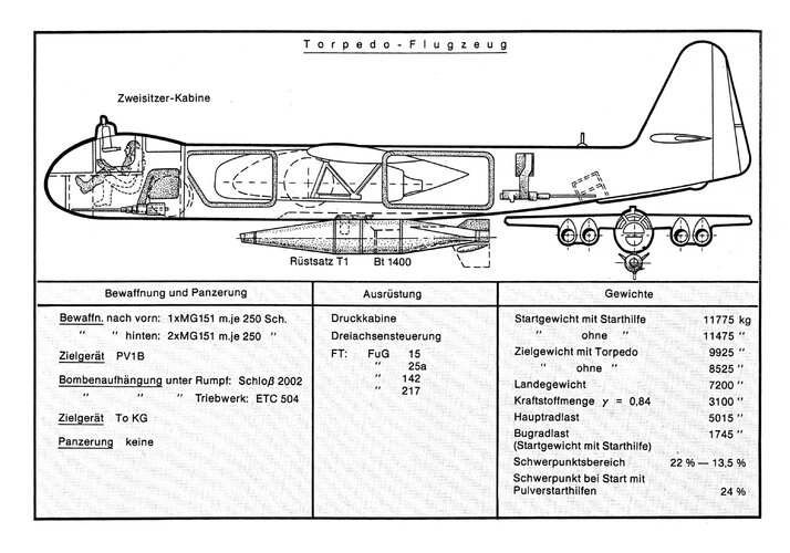
Graf Zeppelin BT 1400 technical data
Length: 4,560 mm, diameter: 620 mm, tailplane span: 1,160 mm, weight: 1,510 kg, warhead 920 kg of Hexanite, range (launched with 20º dive, 600 km/h and 900 m height): 1,600 m, estimated water entry speed: 150 m/sec, estimated underwater path: 60 m (with 180 m/sec, 80 m), lower fin folds to increase ground clearance.
Graf Zeppelin BT 1400 technical data
Length: 4,690 mm, diameter: 620 mm, tailplane span: 1,160 mm, weight: 1,923 kg, warhead 1,050 kg of Hexanite, estimated water entry speed: 200 m/sec, lower fin folds to increase ground clearance.