F-2
ACCESS: Top Secret
- Joined
- 22 May 2020
- Messages
- 773
- Reaction score
- 1,455
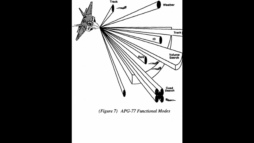
The F-22 is the first US fighter to have an active electronically scanned array (ASEA) radar, the APG-77 developed jointly by Northrop Grumman and Raytheon. Instead of a mechanically driven flat-plate antenna, the radar has an array of some 2,000 transmit/receive modules. These are electronically scanned to create and steer agile beams, which allow search and track modes to be interleaved so that the F-22 pilot maintains situational awareness while the radar provides targeting information, all with a low probability that the APG-77's emissions will be intercepted by enemy sensors.
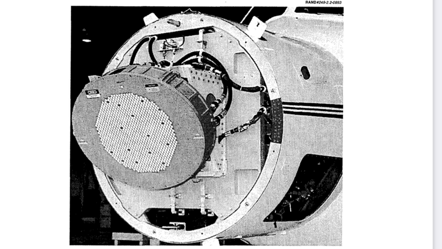
An active array was necessary in the F-22 to enable the radar to be integrated with the fighter's stealthy airframe. Eliminating the large swept volume required to accommodate a mechanically scanned antenna allowed the powerful radar to be installed in a forebody shaped for low radar cross-section - compare the radome size with that of the Boeing F-15. Inside the F-22's wide-bandwidth radome, the APG-77's active array is bolted to a bulkhead which is canted back to deflect radar returns. This also has the effect of increasing the look-up capability of the radar.
In a departure from previous fighter radars, signal and data processing is performed in common integrated processors (CIPs) which handle the same functions for the communication/- navigation/identification and electronic-warfare systems. Support electronics at each sensor send digitised waveforms via fibre-optic databus to the Raytheon-develop CIPs, where the data is fused to create coherent tracks for display to the pilot.
Boeing began flight-testing of a prototype APG-77 in its 757 flying tested in November 1997, following over a year of ground testing in a Northrop Grumman rooftop laboratory. The radar is installed in an F-22 forebody which has been attached to the nose of the 757. The aircraft is now being operated from Northrop Grumman's Baltimore, Maryland, plant to collect data to verify the radar performance model. Only the liquid-cooled radar and CIP are installed for these initial tests. In August, the 757 is scheduled to be returned to Boeing for installation of the other F-22 sensors, and integrated-avionics flight-testing is planned to begin in September. This will precede flight testing of the avionics suite in the fighter itself. The first radar-equipped F-22, the fourth of nine development aircraft, will not be flown until 1999.
Before then, beginning this May, the APG-77 will be exercised thoroughly in Boeing's F-22 Avionics Integration Laboratory (AIL) in Seattle. One of the 11 prototype radars to be built during the current development phase will be installed in the AIL tower at Boeing Field for early testing to identify anomalies before avionics flight-testing begins in earnest in the F-22. A Lockheed T-33 will be used as a calibrated airborne target, allowing data from the APG-77 to be compared with cross-section measurements now being made at Boeing's radar range.
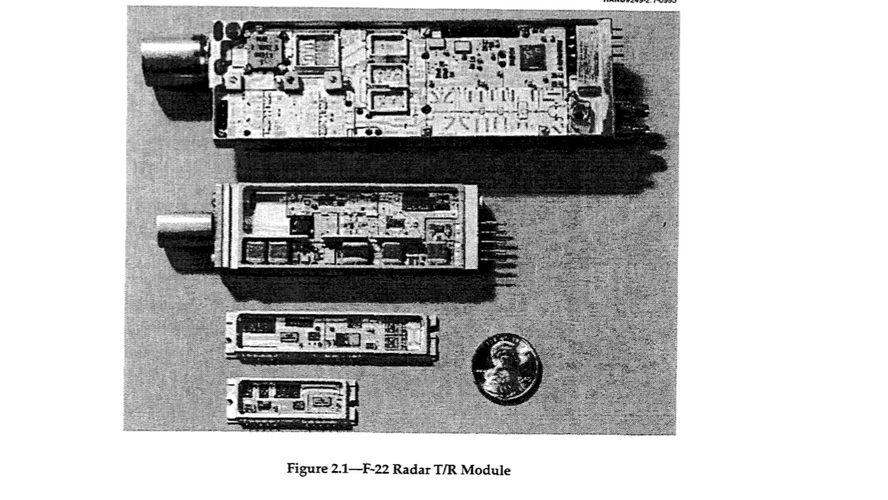
A major part of the APG-77 development effort has been devoted to driving down the size and cost of the solid-state transmit/receive modules. That effort had made it possible to consider upgrading existing fighter radars with active arrays. The reasons for such an upgrade include increased capability and increased reliability: agile, electronically steered, beams allow near-simultaneous multi-mode operation; while radar performance degrades gradually with the failure of individual transmit/receive modules in the array.

Launching forward
Graham Warwick/WASHINGTON DC Lockheed Martin/Boeing's F-22 represents the pinnacle of US military-avionics development, but the air-superiority fighter is not scheduled to become operational until 2005. Meanwhile, manufacturers have begun development of the next generation of avionics, for the...

APG-77 delivered
Northrop Grumman has delivered the first APG-77 radar for F-22 avionics integration. The active array radar will be integrated with other aircraft avionics at Boeing's laboratory in Seattle. The radar, and initial software allowing simultaneous search and track, is already being flown in...

Advanced Air-to-Air Modes
a) RANGE-WHILE-SEARCH (RWS). RWS mode processing provides air-to-air, all-aspect target detection, even in heavy clutter. The radar displays synthetic video on a clutter-free scope when presenting airborne targets, even those flying close to the ground. Ground-moving targets are eliminated by selective filtering and logic. There is a Spotlight mode to scan a small, pilot-selected volume to facilitate the detection of a desired target at the earliest possible time.
b) VELOCITY SEARCH WHILE RANGING (VSR). This mode gives maximum detection-range performance against closing; nose-aspect targets out to 160 nautical miles in both uplook and downlook situations. Through advanced processing within the Advanced Pilotage System Program, an innovative Alert/Confirm mode is activated to achieve a low rate of false alarm, while extending the range capability of the radar beyond the RWS mode.
c) TRACK-WHILE-SCAN. This mode was designed to help a pilot cope with numerically superior forces. To maximize situational awareness and firepower, TWS can track up to 10 targets. Target tracks are displayed for up to 13 seconds after a missed detection before the track file is terminated. This mode has proved effective in multi targeting situations.
d) SINGLE-TARGET TRACK (STT). This mode can be entered from any of the air-to-air search modes by using the side-stick controller and throttle grip. It provides a dependable, accurate track, displaying target parameters and the tactical engagement geometry. The STT submode provides track data to support cueing for short-range and beyond-visual-range air-to-air missile shots. It also provides gun-sight envelope solutions for short-range gunnery modes.
e) SITUATIONAL AWARENESS MODE (SAM). This provides the pilot with an interleaved search and track capability. SAM provides high-quality tracking on one or two targets while searching for other targets in an independent, pilot-selected scan volume. Track accuracy makes this mode ideal for accurate air-to-air missile cueing and all beyond-visual-range (BVR) target engagements.
f) TRACK RETENTION THROUGH THE NOTCH (TRTN). This feature is automatically activated in the track phase for STT and SAM. It allows active tracking when the target is maneuvering into the same Doppler filter as main beam clutter and when the target amplitude is such that the radar can no longer distinguish the target from clutter. The radar will automatically "coast" for a few seconds, until the target emerges from the clutter region.

Advanced Strike Modes
a) ENHANCED REAL BEAM GROUND MAP (GM). This mode generates a map for navigation and target detection out to 80 nautical miles. It was enhanced with a monopulse mapping technique that sharpens map features for hard targets both off-boresight and on the nose. Both direct and offset weapons delivery are possible. A Freeze option stops radar emissions and allows the aircraft to approach the target radar-silent. An extended map mode provides a 4:1 resolution improvement and map expansion
b) DOPPLER BEAM SHARPENING (DBS). When a target of interest is displayed on the ground map at 10-, 20-, or 40-nautical-mile scale, DBS1 mode gives an accurate map of a selected area with an 8:1 azimuth resolution improvement. A resolution of 64:1 is possible with DBS2 mode. This mode gives off-boresight weapons the improved resolution needed for precise launch data. The Freeze option is also available.
c) SEA. This will detect seaborne targets in medium and low sea-state clutter. It is similar to the GM mode, but the radar processor integrates more radar samples to produce a map better tailored for maritime surveillance. Slower scan rates and additional samples increase sea-target detection performance. The Freeze option is available.
d) FIXED TARGET TRACK (FTT). This mode can automatically maintain an accurate track on a stationary target for fix-taking and weapons delivery. FTT is accessible from the GM, GM EXP, SEA, SEA EXP, and DBS modes. Slow-moving targets can be acquired from GM or SEA modes using FTT mode.
e) GROUND MOVING TARGET INDICATION (GMTI). This detects moving targets such as cars, trucks, tanks, other military vehicles, ships, and taxiing aircraft on land or sea out to 40 nautical miles. GMTI mode can also be used to detect moving surface targets in high sea-states. The Freeze option is available.
f) GROUND MOVING TARGET TRACK (GMTT). This mode automatically maintains an accurate track on a moving vehicle (land or sea) for weapons delivery. It is available only from the GMTI mode. Moving targets detected in GMTI can be acquired and tracked using GMTT
g) BEACON (BCN). In this mode, the radar detects a beacon transponder for fix-taking and air-to ground weapons delivery offset. It can also be used for tanker rendezvous. The Freeze option is available.


AN/APG-77 Radar modes
The AN/APG-77 is a multifunction Low probability of intercept radar installed on the F-22 Raptor fighter aircraft. It is solid-state, active electronically scanned array (AESA) radar. The...
fullafterburner.weebly.com
Information on ATF radar dem/Val radars
F-22 program requirements have called for a radar system of
substantially higher capability than any other radar developed. Consequently, instead of incrementally building on the F-22 Dem/Val, US. contractors have had to develop an entirely new radar for FSD.35 This happened despite the fact that the ATF Dem/Val system was judged as highly successful in demonstrating radar operations during flight tests. Nevertheless, the Dem/Val prototype was not viewed as adequate because it did not reach the stringent performance requirements of the F-22 program.3 6
53The SSPA and ATF Dem/Val APAR systems are not p for the final F-22 FSD radar. Rather, the final F-22 radar will be an entirely different system. Del, D. and W. Sweetman, August
Active Device Requirements
Microwave performance specifications have also led to stringent requirements for T/R module active devices. In the past, such requirements posed as bottlenecks with respect to available solid-state technology. Historically, the feasibility of prototype technology has been contingent mostly on new developments in solid-state technology. For example, system requirements have dictated T/R modules capable of several watts of peak output power at power- added efficiencies of almost 20 percent. Throughout the 1960s and early 70s, however, performance limitations of contemporary solid-state technology had forestalled prospects of meeting these requirements for airborne radar.8
X-band APAR prototypes developed before the late 1970s could not satisfy contemporary requirements because the latest solid-state devices could not
amplify signals efficiently at X-band. These latest devices were made of silicon, which as a material inherently limits the switching speed of the device. Consequently, T/R modules developed during this time had suffered from very
dai•
6Medanical stre caused by a high mismatch in e•asion rates can be severe enough to •aMm&.e 1id.
8
Interview with radar engners at Westinghouse Electric. McQuiddy, D., et aL, op. cit.
low efficiency and duty cycles. Array prototypes containing such devices could not generate the requisite power levels without overheating. 9,10
Higher tansmit power and efficiency became a possibility with the development of GaAs transistor technology. GaAs is an expensive semiconductor with switching speeds six times faster than silicon.1 1 Because GaAs is fast enough to amplify X-band signals directly, GaAs amplifiers have enabled the development of microwave circuits for T/R modules that met the stringent power and efficiency requirements of contemporary airborne fire control applications-1 In 1980, GaAs single-transistor chips integrated within a hybrid circuit were used to amplify and phase shift signals within X-band T/R modules developed at the Naval Research Laboratory (NRL). By 1985, the NRL program completed 45 X-band T/R modules, which demonstrated feasible performance levels in terms of ftansmit power, power-added efficiency, noise figure, and bandwidth.
After the NRL program, the Air Force began funding the Solid-State Phased Array (SSPA) program to develop two radar prototypes containing T/R modules
with GaAs microwave integrated circuit (MIC) amplifiers. SSPA was able to demonstrate simple radar functions at feasible performance levels. The success
of SSPA in ground tests led to the DoD decision to develop an X-band APAR for the Demoznstration/Validation (Dem/Val) phase of the Advanced Tactical Fighter (ATF) progrm? 3 later to become the F-22 program.
Although GaAs technology was developed to improve circuit performance, recent R&D has focused on miniaturizing circuits by integrating more microwave functions into GaAs circuits. The problem with SSPA and earlier programs was that their hybrid MICs1 4 occupied much of the space and drove up the weight of
uNg the 9O6s and 19•O, Molecular Ee•mrocs for Radar Applicatiom (ERA) and Reliable AdvancedSolid-StateRadar(RASSR)programaimedtocircumventlimitationsofsilicon. Module amplifiers were operating at a frequency lower than X-band, and the outputs to these amplifier. were connectedtohequencymultipliersconvertmingtheoutputsignaltoX-band. Nevertheless,thepower lossesfromfrequencyconversionreducedmoduleefficienciestoIor2percent farbelowwhatz considered acceptable for airborne radar. McQuiddy, D., et al., op. cit.
10AltoughlimitedinX-bandpedormance, silicondevicesarecapableofdirectRF
amplificaion at frequencies lower than X-band. Thus, APAR usn silcon-basedl T/R modules had been developed for larger, surface-based systems that can support lower wavelength radiation. Two examples include the SPY-I Aegis fire control system and the PAVE PAWS early warning missile detectionsystem. Sweetman,W.,"ActiveArrayforATF,"op.cit
llAbe,NL,"PresentStatusandFutureprospectsofCompoundSemiconductorLS9 Tedmology," /-n&doW Sla KairoGIjutsu,June 27,1991, pp. 73-78, translated nto English by JPRSJapm Sckeov & Tedimoog, Apr•I15, 1992. p.15.
UmcQuiddy,D.,"Solid-StateRadar'sPathtoGaAs," IEEEMkrowwThwmy&Techniques: Syvnpasim Digest,1982.
13
M•cQuiddy, D.,etaL,op.cit.
14Hybrid MICs tended to be among the bulkiest circuits within T/R modules because each
consisted of several single-device GaAs chips (also called discretes) mounted and wired on a thick carrier. ]bid., p. 71.
17
18
T/R moduls To reduce module size, US. industry developed GaAs MMICs in the mid-1980s as functional replacements of hybrid MICs. MMICs, which involves the integration of several microwave devices on a single chip, have replaced hybrid MICs several times their size and have allowed for dramatic reductionsinmodulesize,partcount,andassemblycosts.15 MMICtechnology is very costly, however. The utilization of MMIC within modules has introduced additional complications to module assembly. The impact of MMIC technology insertion on the costs of T/R modules is addressed later in this section.
Picture of T/R module and installed dem/Val radar


