Engine power considerations in performance calculations"

HoHun

ACCESS: Top Secret
Joined
9 October 2021
Messages
779
Reaction score
779
Hi Tomo,

Goes without saying that I'd just love to see flight tests of many, many pre-war British and German aircraft

I just had a look at Hermann's "Focke-Wulf Fw 187", and he actually reproces some pages of a Rechlin test. (Frustratingly, not all of them, but the performance pages are there, at least.)

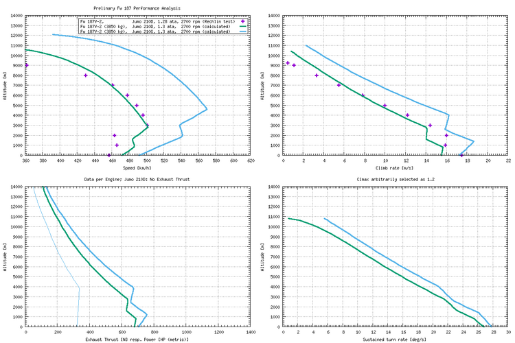
It's for the Fw 187V2 with Jumo 210D engine, 3 m propeller diameter, at 2700 rpm, 1.28 ata, flown at 3850 kg. My guess is that this might be a bit less than the normal take-off weight ... while I don't have a weight breakdown for the V2, the A-0 is probably not all that much heavier, and it weighs in at 3723 kg empty equipped (Rüstgewicht). However, weight doesn't affect top speed much anyway ... I calculate a top speed loss of about 6 km/h when increasing weight from 3850 kg to 5000 kg.

I've prepared a diagram with the tested data, compared to a calucation of performance based on the data from the test, along with an estimate of the speeds achievable with the V2 if it had been powered by the Jumo 210G (as was used on the V3, which due to an accident didn't get to be tested at Rechlin).

I have to admit that I was a bit suprised by the big jump in performance between the Jumo 210D and the Jumo 210G, but the G actually is a much more advanced engine, featuring fuel injection and a supercharger providing a much increased full throttle height. Additionally, it was fitted with jet nozzle exhausts to exploit exhaust thrust, and (according to a remark in the V4 Baubeschreibung) also was set up to exploit the ram effect of a forward-facing intake, giving an additional boost in full throttle height that resulted in a yet higher absolute top speed.

The (two-seater) V4 actually was a bit slower than the V2 would have been, according to my calculations, but I guess that only shows you can't just add a second crew member to a single-seater design without sacrificing a bit of performance.

Compared to the 564 km/h @ 4600 m I calculated for the single-seater at 5000 kg flying weight, the Focke-Wulf number for the two-seater with the same engines at the same weight is 545 km/h @ 4600 m, or a loss of about 20 km/h top speed.

Here's the diagram:

Fw187_Performance_1.png

Some notes: The Rechlin test data did not feature the characteristics points, only one value at each full kilometer height, so I didn't draw a line through the points. The Rechlin-measured top speed of 501 km/h @ 3000 m was achieved at 1.26 ata instead of the maximum of 1.28 ata, so I figure the real top speed was probably about 502 km/h @ 2800 m.

My calculations deviate from Rechlin data in low supercharger gear, and while I'm low in top speed, I'm high in climb. That makes no sense at all ... if I had only the speed graph, I'd suspect some peculiarity of low supercharger gear operation, such as automatically engaged carburettor heating or something, but as the climb graph is off in the opposite sense, I think not all of the Rechlin data points are actually sensible. I suspect their climb data is too high for low altitude ... nothing serious, there are small glitches like that in a lot of the historic data sets, from all sides.

(If 3850 kg isn't the full normal take-off weight, the climb rate should actually be lower anyway, if one adheres to the convention on showing the climb rate normal take-off weight for comparison purposes.)

I have two slightly different power charts for the Jumo 210D, and they are for 1.3 ata while the Rechlin test was run at 1.28 ata. I'm also not entirely sure of the reduction gear ratio, which affects top speed above full throttle height ... a page from a pre-war catalogue shows a gear ratio of 0.628, but the engine portrayed there is referred to as Jumo 210Da, and descrived as having a 3.4 km rated altitude, while the one used on the Fw 187V2 has a full throttle height of just 2.8 km.

Regards,

Henning (HoHun)
 
Compared to the 564 km/h @ 4600 m I calculated for the single-seater at 5000 kg flying weight, the Focke-Wulf number for the two-seater with the same engines at the same weight is 545 km/h @ 4600 m, or a loss of about 20 km/h top speed.

How much the two 20mm installations should cost in high speed? Camouflage paint vs. bare metal finish? Aerial mast will also subtract a few km/h.
 
@HoHun - am I better off with English-language book about the Fw 187 (by Hermann), or the German-language one (by Petrick and Hermann)?
 
Hi Tomo,

How much the two 20mm installations should cost in high speed? Camouflage paint vs. bare metal finish? Aerial mast will also subtract a few km/h.

The difference is the cumulative effect of all the changes between the Fw 187V-2 and the A-0.

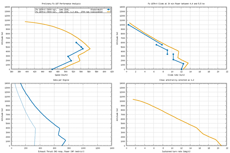
Here's a graphical comparison between the data from the V-2, extrapolated to the same engines and flying weight as the A-0, and the data from the Focke-Wulf Baubeschreibung for the A-0:

Fw187_Performance.png

The Focke-Wulf climb graph has a "loose section" between 4.4 and 5.5 km altitude because it basically shows how you'd do a high-performance climb to altitude. You can only use full power for 5 minutes, then throttle back and reduce rpm to climb power settings, and at 5.5 km you can then increase rpm again (where manifold pressure is below the maximum allowable anyway).

Of course, if you were going into a fight between 4.4 and 5.5 km, you could use full power there just fine, as the limit is time, not altitude.

(The increase in rpm above full throttle height is not entirely unusual, you can see that in some Spitfire climb graphs on wwiiaircraftperformance.org, too. It's a bit of a presentation artifact, as it's based on the convention of showing a continuous climb. Useful for calculating time to altitude!)

Regards,

Henning (HoHun)
 
Hi Tomo,

How much the two 20mm installations should cost in high speed? Camouflage paint vs. bare metal finish? Aerial mast will also subtract a few km/h.

The difference is the cumulative effect of all the changes between the Fw 187V-2 and the A-0.

Here's a graphical comparison between the data from the V-2, extrapolated to the same engines and flying weight as the A-0, and the data from the Focke-Wulf Baubeschreibung for the A-0:

View attachment 691277

The Focke-Wulf climb graph has a "loose section" between 4.4 and 5.5 km altitude because it basically shows how you'd do a high-performance climb to altitude. You can only use full power for 5 minutes, then throttle back and reduce rpm to climb power settings, and at 5.5 km you can then increase rpm again (where manifold pressure is below the maximum allowable anyway).

Of course, if you were going into a fight between 4.4 and 5.5 km, you could use full power there just fine, as the limit is time, not altitude.

(The increase in rpm above full throttle height is not entirely unusual, you can see that in some Spitfire climb graphs on wwiiaircraftperformance.org, too. It's a bit of a presentation artifact, as it's based on the convention of showing a continuous climb. Useful for calculating time to altitude!)

Regards,

Henning (HoHun)

As long as the charging system can built up the full boost pressure, the exhaust thrust and power should rise with an increase in speed and decrese in air pressure, there must be something wrond in this calculations. Lower back pressure means higher expansion ratio and higher speed meens higher propulsion efficiency.
 
Hi Nicknick,

As long as the charging system can built up the full boost pressure, the exhaust thrust and power should rise with an increase in speed and decrese in air pressure, there must be something wrond in this calculations.

So where's the contradiction to what I posted? If you can't decribe that concisely and completely in a single post, please open a separate thread for "Engine power considerations in performance calculations" so we don't hi-jack this type-specific thread.

Regards,

Henning (HoHun)
 
IT belongs here because your curves for the exhaust thrust/power are clearly wrong. How Die you calculate them?
 
Hi Nicknick,

IT belongs here because your curves for the exhaust thrust/power are clearly wrong. How Die you calculate them?

Sorry, to take you serious, you'd have to tell me CONCISELY AND COMPLETELY what you think is wrong.

To get an answer, you'd have to do so IN A NEW THREAD.

These emphasized parts are non-negotiable because I know how messy threads get when they involve me trying to explain something to you.

Regards,

Henning (HoHun)
 
We start with a simple check. In you graph in the bottom left, we can read that we have 320 N at sea level. The speed (I think, you used the blue colour consistently for the same engine), 462 km/h or 128 m/2. For the corresponding thrust power you need a very simple equation:

P=F*v = 320 * 128 = 41 kW

This is a totally realistic value for the exhaust thrust. You diagram shows about 700 hp which is more than 10 times too much…

edit: there was a small typo (161 m/s instead of 128 m/s), but it didn't change anything about the fact
 
Last edited:
At 4000 m we have a speed of 545 km/h or 151 m/s an a thrust of 330 N, so the thrust power would be about 50 kW. It is clear, that the power must be higher if both, the thrust force and speed is greater, but in your diagram, the power is even less than at ground level! Not only the values are false, but also the connections are clearly not understood. This is just simple mechanics, for calculating the exhaust thrust you need some knowledge of thermodynamics, you should start with the simple things before you try that!
 
The way I read the bottom left graph: the light blue line, which touches the X-axis at 320 applies to exhaust thrust in Newtons. The dark blue line, which touches the X-axis at 700, applies to power output of the engine in hp.
Both figures seem plausible to me. @Nicknick Am I missing something?
 
I used exactly that 320 N and multiplied it with the corrosponding speed in m/s. The result doesn't fit to the given thrust horsepower at all. Simple physics

Power [Watt] = Force [N] x speed [m/s]
 
You are reading a different physics book than mine.
Exhaust thrust 320N and engine output 700hp at the crankshaft are separate quantities.

<edit>Your formula to calculate power is wrong. I take that back.</edit>
In this case, power thrust is the instantaneous force generated by the engine. The resultant propulsive force is less because of transmission loss of the propeller. The propulsive force needs to be maintained for an interval of time to reach the given speed (but you haven't taken drag or mass into account), or maintained for an indeterminate interval to maintain that speed against drag, dependent on the vehicle's shape and size.

To calculate the energy in Wh needed to reach a given speed, power is inappropriate. You need work W = 0.5 x mv^2. Again, this is without taking drag into account.
 
Last edited:
Oh boy, there is more than one type of work on this planet...

BTW, you might go back and see, that even Henning realized his failure and liked my prevouis posting.

700 hp is the power by the exhaust thrust accoding the the graphs, not the engine power. The corrosponding crank shaft power (if you mean that) is by a factor of 1/propefficiency higher, the difference is not that significant (about 15 % more than the thrust power).

If you have no clue of physics, you should be thinking more than once before you start posting about it....
 
Last edited:
Oh boy, there is more than one type of work on this plantet...
I thought I'd use the type of work W as used in Newtonian physics. YMMV.
BTW, you might go back and see, that even Henning realized his failure and liked my prevouis posting.
He also liked mine. I like to think he was just being nice.

<edit>
700 hp is the power by the exhaust thrust accoding the the graphs, not the engine power.
Your interpretation. Henning might be able to answer that, he drew the graphs.
</edit>

If you have no clue of physics, you should be thinking more than once before you start posting about it....
Righto.
 
Last edited:
Newton realized that things like energy, gravitation, force are all related. BTW i was writing about power in Watt [W] not work...

Did you have physics in shool?
 
And at university. Part of me reading biology. We're drifting off topic.
 
Thanks god, that mechanic is raerly an important part of biology...

So might realize that power can be a force multiplied with a speed, or a stream of a volume multiplied with a pressure difference, or a mass with a heat capacity multiplied with a temperature difference in a given time and many more thinks on this planet.

Youre equation is the kinetic energy (mearured in Joule, not Watts....):

W = 0.5 x mv^2.

What does it have to do with the power of the exhaust thrust???
 
Last edited:
A working knowledge of mechanics is indispensible in functional anatomy.

Power is the rate with respect to time at which work is done; it is the time derivative of work:
P = (dW)/ (dt) where P is power, W is work, and t is time.

If a constant force F is applied throughout a distance x, the work done is defined as W = F ⋅ x
In this case, power can be written as:
P = dW/dt = (d/dt) ( F ⋅ x ) = F ⋅ (dx/dt) = F ⋅ v

Your formula P = F ⋅ v
- is valid for a spherical cow moving in a vacuum
- is not valid for calculating the combined thrust (exhaust/propeller) of an Fw 187, powered by two 700hp Jumo 210Gs at sea level, because you have not taken drag into account
 
Its not the combined thrust, just take a look on the diagram, it is the exhaust thrust in Newton and the exhaust power in Hp (Horsepower).

P=F*v is always valid, no matter if there is a vacuum or if we are 10 km deep in the Ocean, this is universal! Glad you started looking in a book or on Wikipedia what this means! So what is you intention with the kinetic energy?
 
Its not the combined thrust, just take a look on the diagram, it is the exhaust thrust in Newton and the exhaust power in Hp (Horsepower).
700hp, measured at the crankshaft, is a Jumo 210G's power output at sea level. Not exhaust power. Ask Henning, he drew the graph.
 
There is written exhaust thrust and power, but even if this would be the engine power, the steps in the power during the switching of the charging system must bee seen in the thrust curve (Newton) which is not the case.

As an engine developer, I know what it takes to calculate the exhaust thrust, this is not a trivial tusk. You need at least an estimation of the cylinder filling (mass, temperature, volume), the exhaust timing and isentropic flow values and the nossel geometry for a proper calculation. I doubt, that he taken anything of that into account, if so, he should puplish his approach.
 
Last edited:
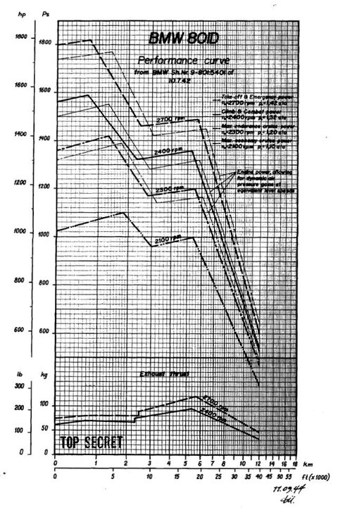
801Dchart.JPG


Here we see the exhaust thrust of the BMW 801, we can clearly see, the exhaust thrust is reacting directly to every switch in the charging system. The smooth line of Hohuns diagram up to 4000 m height, indicates, that this was just drawn by guessing, but surly not by any thermodynamic analysis.

I think we do have the same diagram somewhere here, but this is from :https://ww2aircraft.net/forum/threads/on-big-radials.40758/page-2
 

Similar threads

Please donate to support the forum.

Back
Top Bottom