Douglas Model 1265 Parasite Bomber

circle-5

ACCESS: Top Secret
Top Contributor
Senior Member
Joined
31 May 2009
Messages
1,154
Reaction score
593
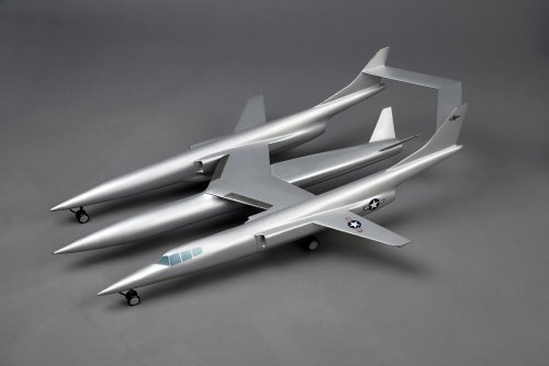
Here's a factory Douglas model of a supersonic, composite bomber. Does anybody know what its designation was? The center pod can be jettisoned. It contains a third turbojet and presumably some fuel and a nuclear warhead. Cockpit appears to sit three crew members. An semi-educated guess dates this project from around 1950-1952.

The commonly-known Douglas GEBO (GEneral BOmber) proposal was the Model 2091. Another example is the Douglas Model 1209. I feel this unidentified airplane better fits the specifications for MX-1626 (Phase I) studies, but don't have any solid evidence.

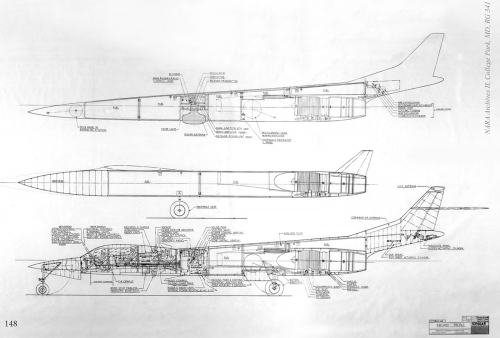
I hope someone like Doctor House might have everything I need about this design, including large scale drawings, declassified reports, mission profiles etc ...
 

Attachments

  • Douglas Supersonic Pod Bomber 02e.jpg
    Douglas Supersonic Pod Bomber 02e.jpg
    409.2 KB · Views: 499
For context, Model 1209.

https://retromechanix.com/douglas-model-1209-high-speed-composite-bomber/
 

Attachments

  • Douglas-Model-1209-High-Speed-Composite-Bomber-a.jpg
    Douglas-Model-1209-High-Speed-Composite-Bomber-a.jpg
    2 MB · Views: 656
PaulMM (Overscan) said:
The model is arguably more Stillettoish than 1209. Where's the intake on the centre pod?

Side intakes under the wing, similar to the intakes on both fuselages. I'll take more photos later ...
 
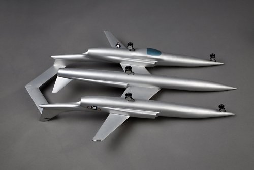
The underside view shows the large weapons pod, with its own jet engine, butterfly tail and main gear bogie. Not sure what that large, panoramic ventral window is for (under the port fuselage), but it's part of a large bulge or blister. Wish I had an inboard profile ...

The inverted-sweep horizontal stabilizer is noteworthy.
 

Attachments

  • Douglas Supersonic Pod Bomber 03e.jpg
    Douglas Supersonic Pod Bomber 03e.jpg
    447 KB · Views: 404
I'd describe the horizontal tailplane as conventionally swept since it extends aft from its attach points, but the arrangement is strange enough that its really in its own category. Sweeping the tailplane in the other direction would, I think, produce the same sort of divergent stresses seen in FSW designs.
 
Hmmmm...... Model 1265 perhaps?

(P.138-149 of American Aerospace Archive 5 - Mother ships, Parasites & More by Jared Zichek)

The Model 1251 was followed by the Model 1265, an even more radical parasite bomber dating from March 20, 1951. It was a twin fuselage medium bomber also powered by three P&W XJ53-GE-X25 turbojets, one of which was located in the large droppable central bomb/fuel pod. The others were installed in the aft portion of each fuselage, with side inlets providing air to each. Other droppable components included 2 subsonic fuel tanks on the wing tips, which were likely released along with the central pod during the attack phase of the mission. The revised configuration of the parasite bomber permitted the bomb to be carried between the fuselages, creating a more compact arrangement which provided greater ground clearance when attached to the Model 1240 carrier aircraft.

Like its larger parent, the Model 1265 was an asymmetric design with the cockpit in the left fuselage and radar antenna mounted underneath the right fuselage. Unlike the skid-equipped Model 1251, the Model 1265 featured relatively conventional wheeled landing gear, with 2 nose gears, 2 main gears and 1 auxiliary droppable main gear for the pod. It carried 3 crewmen equipped with downward firing ejection seats like the Model 1251-A. The Model 1265 had a design gross weight of 125,000 lbs and a weight empty of 46,720 lbs, making it substantially heavier than its predecessors.

Plate 191 provides interesting details of how the Model 1265 was carried, released and retrieved by the Model 1240. In this drawing, the parasite bomber featured an extendable probe mounted at the tip of the wing center section; this interfaced with a target boom carried by the Model 1240. Interphone communication between the carrier boom operator and the parasite pilot was provided through the connection of these booms, which aided coordination during retraction or extension of the parasite. Two aft booms were also provided on the carrier aircraft, which corresponded to latches on top of each fuselage of the parasite. Full details of the releasing and retrieving procedures are shown at the far right of the blueprint.

The Model 1240/1265 combination also featured an unusual telescoping personnel passage tube which connected the cockpit of the parasite to the crawl tube in the carrier aircraft's central wing section, which is illustrated at the far left of the blueprint. An amazing if somewhat improbable study.
 

Attachments

  • Model1265.png
    Model1265.png
    563.7 KB · Views: 397
  • Model1265-2.png
    Model1265-2.png
    823.6 KB · Views: 375
PaulMM (Overscan) said:
Hmmmm...... Model 1265 perhaps?

(P.138-149 of American Aerospace Archive 5 - Mother ships, Parasites & More by Jared Zichek)

Thank you Overscan – you nailed it! The sad part is that I have this book on my shelf, but no recollection of seeing this project in it.

As always, Jared Zichek did a wonderful job documenting oddities like the Douglas 1265. Now I know what these wingtip rails were for. And it looks like Scott was correct about the big underside radar blister. A powered weapons pod on a parasite bomber hooked up to a mother-ship carrier. Six crewmen and seven engines of two types ... Those were the days!

I think the name of this topic can be changed to: Douglas Model 1265 Parasite Bomber
 

Attachments

  • Food Chain.jpg
    Food Chain.jpg
    627.5 KB · Views: 137

Please donate to support the forum.

Back
Top Bottom