Design Exercise: 1919 Type I Water Cooled Pursuit Aircraft

Dynoman

ACCESS: Top Secret
Senior Member
Joined
29 July 2009
Messages
1,627
Reaction score
1,942
Using 1919 aircraft design examples, era engines, weapons, and early post-WWI aircraft construction techniques, an interesting exercise can be made in responding to the 1919 US Army Air Service requirements for a Type I water cooled pursuit aircraft. The original specifications are listed below. Its competition was the Engineering Division's PW-1, Loening PW-2, Orenco PW-3, Gallaudet PW-4, Fokker's PW-5/PW-6/PW-7, Curtis PW-8, and Boeing's PW-9, which were developed between 1919-1923. Using these and other aircraft for historical weight fractions, NACA airfoil data, Woodhouse's 1919 publications on aircraft design and construction, and various encyclopedias on era engines and systems, a preliminary design can be created.

Type I Requirements:
Single Seat Day Pursuit Aircraft
Water cooled engine
Maximum speed of 145 mph at 15,000 ft.
Climb to 20,000 ft. in 21 minutes
Service Ceiling of 23,750 ft.
Endurance of 2.5 hours at 15,000 ft., with an additional half hour at sea level
Useful load of 525 lbs.
Fixed armament of .30 caliber or .50 caliber machine guns

Conceptual design effort:
To understand and respond to the Type I mission requirements
To use state-of-the-art technologies for the 1919-1923 time period as practical as possible
To find creative ways to integrate the technologies to make it a formidable and sustainable design
To consider the materials, manufacturing processes and design tools used in the same period

From this preliminary design effort the hope is to generate:
Configuration
Weight estimation
Airfoil selection
Wing loading and thrust loading
Wing design
Fuselage, landing gear, and control surface design
System and armament placement
CG Calculations
Performance estimates
Preliminary stability data

For fun, the aircraft company name is SPEEDCO for Secret Projects-Forum Engineering Evaluation and Design Company and it's designation is PW-10.
 
Last edited:
Conceptual Design

Responding to the Type I requirements, the mission of the pursuit (fighter) aircraft is to gain air superiority or control of the airspace over the battlefield by destroying enemy aircraft. Positive characteristics of a pursuit aircraft are (in no particular order):

High firepower
High speed
High maneuverability
High visibility
High damage tolerance
High loiter times
High rate of climb
 
Conceptual Design - Higher Firepower

During the war the Lewis and the Vickers were the standard guns for the Allies aircraft. The standard aircraft machine gun of the era (1919-1920) was the air cooled .30 caliber M1919 Browning. This weapon provided higher rates of fire than the larger caliber weapons and was considered adequate against aircraft designs of the day. The M1921 was an air cooled .50 caliber machine gun and would later be adopted by the services, but was considered heavy for aircraft installation and not seriously used until the early 1930s. The Marlin .30 caliber was also produced in relatively large numbers in the US at the end of the war. It had a rate of fire between 630-650 rds/min.

All of the 1919 Type I aircraft proposed to the US Army (i.e. PW-1 through PW-9) had .30 caliber designs.

Era Handbook of Instructions for Aircraft Design
 
Conceptual Design - Higher Firepower

For this example we'll use two Browning .30 in M1919 machine guns as the baseline of the design. Its standard use in the military provides sufficient parts availability and general field serviceability. Documentation of its design, performance, and installation are also relatively available for the purpose (which is for fun) of this design exercise. Sizing the aircraft may allow for other larger weapons.

The M1919 has a rate of fire of 400-600 rds/min, a muzzle velocity of 2,800 ft/s, weighs 31 lbs each, and is belt fed (typically 250 rounds). Its overall length is 41 inches and barrel length is 24 inches.
 

Attachments

  • m1919-3a.jpg
    m1919-3a.jpg
    55.2 KB · Views: 167
Last edited:
Concept Design - Higher Speed

According to the Bulletin of the Airplane Engineering Department constant-speed propeller systems were successfully being tested in June 1918. This system would certainly aid in the efficient performance of the aircraft. However, I don't think that any constant-speed system was used in a production aircraft until 1932. If that is not the case and it could apply it to this design in the 1919-1923 era let me know.

 
Last edited:
Concept Design - Higher Speed

The Curtiss PW-8 used a Curtiss D-12 side-mounted exhaust driven turbosupercharger. It was successful, having flown 190 mph at 20,000 ft. A few more years later the Boeing PW-9 was fitted with a turbosupercharger in 1925 and successfully flown. General Electric was developing superchargers along with McCook airfields Experimental Section and there appears to be sufficient data to use in the designs performance calculations (particularly the modified D-12). Despite being a technological gamble to implement this technology, which is still under development in 1919, the gamble is well worth it in order to keep the aircraft on the cutting-edge of technology for the 'next' pursuit aircraft in the US Army Air Service.
 
Concept Design - Higher Speed

In an effort to significantly increase the speed and overall performance of the design the drag of the aircraft should be minimized as much as possible (i.e. skin friction, flat plate, separation, profile, interference, parasite, and induced drag).

To minimize skin friction drag the design should be as smooth as possible by reducing surface roughness. The design should utilize the latest dope, fabric, and stitching that maximizes strength while minimizing skin roughness. An all metal aircraft (eg. Junkers DI) or a mix of metal structure (eg. Boeing PW-9) to arrive at the needed strength and minimum surface roughness may be better solution. Fabric covered aircraft in 1919 were covered with linen, cotton, or silk at times. These were sewn together and covered with a stretching varnish and a finishing varnish. Metal skins were often duralumin sheets riveted together.

To reduce flat plat drag the design should have the smallest frontal area as possible. Many WWI era aircraft have large frontal areas for radiators and radial/rotary engines. Their cabanes (holding the wing to the fuselage), wing struts, landing gear, and wires also add to the frontal area. For this design the minimization of these structures should be considered. This includes minimal bays (the number of spaces created between wings of a biplane/triplane and struts), reducing the number of bracing wires or using streamlined wires, minimizing landing gear length, etc.

To reduce separation drag the design should not have structures that have abrupt changes in shape. The smoothest contouring should be used that blends one structural element into the next. Fairings and fillets would help to minimize drag, especially from cowlings, wing roots, struts, and landing gear. This era aircraft did not see considerable use of fillets. Rounded surfaces were used in structural edges and were beginning to be be used in fuselage and cowling designs.

To minimize profile drag the airfoil selection should be designed to develop maximum lift with minimum drag over the angles of attack expected for the aircraft. For the pursuit design the aircraft should have the thinnest airfoil profile that develops needed lift, while having adequate internal volume for structural load supporting elements (i.e. spars, ribs, control cabling, etc.). Junkers conducted studies in 1917-1918 that proved the upper and lower cambers of the wing could be convex without suffering significant drag. Wings or the era typically had convex upper cambers and concave lower cambers.

To reduce interference drag the aircraft should be designed with as few components extending from the aircraft as possible. As clean a design as possible that minimizes the amount of structures (e.g. struts, wires, landing gear structures, etc.) exposed to the aerodynamic flow field.

These parasite related drags will be considered in whole as the form drag for the entire aircraft as we continue to flush out the configuration of the aircraft. Some of these drags will include engine cooling drag, stores drag, flap and trim drag.

Induced drag, a by-product of lift, is the drag that occurs from an imbalance of high and low pressure forces around the aircraft that results in downwash and related vortices found at the wing tips and other locations on the aircraft where relatively high and low pressures mix (eg. strakes, VGs, etc.). Here we can examine the wing shape, such as using a tapered wing, elliptical wing, swept wing, etc. Most aircraft wings in the 1919 era were straight wings (outside of a few examples such as the Burgess Dunne D.8 and LGF Roland Pfeil) and had rounded, raked, or straight edge wing tips. For the baseline design a straight wing with rounded tips will be considered. Flaps were also available as they were introduced in 1916 on the Fairey Hamble Baby. Flaps are a means of increasing the relative camber to increase lift (usually in the first 20 degrees and drag in the last 10 or 20 degrees) allowing the aircraft to approach in the landing phase of flight at a lower speed and steeper angle of descent.

Unique configurations, such as the Vickers Gunbus or the Burgess Dunne D.8 should also be considered in this early conceptual phase as the optimal design is resolved.
 
Last edited:
Start by looking at the modern, kit replicas designed by the like of Robert Baslee. They are really stand-off scale replicas with subtle changes to balance and control areas to vastly improve stability and control. Simply moving the center-of-gravity forward of the center-of-lift tames their handling compared with the originals. Baslees' subtle modifications make his replicas flyable by modern, low-time private pilots. Improved handling would reduce the large numbers of landing accidents suffered by young pilots during WW1.
Simple changes to landing gear alignment can also vastly reduce landing accidents.
Differential ailerons could tame adverse yaw. Aerodynamically balanced controls could reduce control forces (felt on stick and rudder pedals). Mass balanced controls could eliminate flutter.
Even more subtle changes (e.g. dihedral) can also reduce the pilot's work-load (improved roll stability) giving him more time to look for enemy airplanes.

Reducing drag should be a key factor, considering the low power of most WW1 engines.
Wires and struts were major drag-producers back then, so fewer wires and struts make a big difference. A simple round wire makes as much drag as a streamlined wire 3 times the diameter. So teardrop shaped wires will help reduce drag, but still, the fewer wires the better. This is where low-wing monoplanes are faster than parasol monoplanes. Look at the thick cantilever wings made by Fokker and Junkers. As modern kitplanes (e.g. Zenith) have proven, a wing up to 18 percent thickness produces plenty of lift but little extra drag. It can also be made lighter than a thinner cantilever wing.
The 12 percent thick (ala. Spitfire) were really only relevant faster than 300 knots and when approaching the speed of sound. While no WW2 airplanes were supersonic, they sometimes had experienced problems with localized supersonic airflow.
Blunt leading edges may add a bit of extra drag, but they also tame stalls. Perhaps the ideal leading edge is deeply cambered (ala. Robertson STOL modifications. Swept wing tips mimic the Schumann planforms now popular with competition sailplanes and Reno Air Racers.

Another form of interference drag is the gap between the upper and lower wings of biplanes and triplanes. By 1932, George E. Gere had learned that a gap of 1.5 chords or larger minimized interference between upper and lower wings of biplanes. For other ideas about to reduce drag see Biplane Reno Air Racers.

By the end of the war, Junkers was also proving that it was possible to build cantilever landing gear legs. Retractable landing gear is not really important until airspeeds exceed 200 knots (see modern Cirrus, RV kitplanes, etc.). Fancy faired wheel pants might look pretty, but I they would fill up with mud on typical WW1 grass airstrips. Whether or not to wear wheel pants would end up being a squadron decision based upon local airstrip conditions. Perhaps Maule-style, partial wheel fairings would help reduce drag without the risk of clogging.
Since external springs were drag-prone, I suggest Junkers style cantilever struts with the shock absorbers inside the fuselage (ala. 1930s vintage Luscombe or late 1940s vintage Aeronca).

As for armament, I prefer the motor-cannons built by Hispano-Suiza towards the end of the war. Even if you only mount a (.50 caliber 12.7 mm) heavy machine gun or a single 20 mm cannon, you vastly simplify construction, alignment, aiming and tactics.

Fully enclosed cockpits could both reduce drag and improve pilot comfort, but really depend upon optically clear windows.

By 1918, German aces wore crude parachutes. Reliable pilot emergency parachutes only became practical during the 1920s. Given my knowledge of modern parachutes, I could build compact, reliable PEPs using WW1 vintage materials, tools and hardware.
Interference drag was not much of a problem during WW1 because most of the wing-fuselage intersections were at 90 degrees. Even as far back as the 1930s, British light plane designers (Percival, Hunting, deHavilland, etc.) proved that simple 90 degree intersections reduced interference drag where horizontal surfaces meet the fuselage (see Douglas AD-1 Skyraider or any WW2 Grumman fighter)..

A more subtle solution to interference drag is keeping the fuselage constant cross-section through the wing root. This also simplifies construction. It was never really an issue during WW1 because most fuselages were already straight across wing roots. So none of those gracefully curved rear fuselages (ala. Albatross) because they create too much drag at the trailing edge of the wing and are a bugger to streamline with wing root filets.

Reducing cooling drag is easy with liquid-cooled engines but more complex with radial/rotary engines. Rotary engines still need to rotate to cool on the ground. Adjustable cowling flaps would help, but for God's sake, don't install any on the top of the cowling where they can interfere with visibility for landing. Rotary engines might benefit from tighter cowlings, but still might need supplemental fans for cooling on the ground.
OTOH liquid-cooled engines could benefit (reduced profile drag) from burying radiators farther aft in the fuselage (see 1930s vintage Napier Heston-Racer or WW2 vintage P-51 Mustang).
 
Last edited:
I really like this as an idea - and possibly pooling information about engines and components (etc.) We could even build up the ability to do some basic structural calculations.

However... I see a significant problem in estimating the drag from external bracing wires (particularly since they vibrate). This could make it difficult to get even approximate performance estimates for a design prior to building it... and the fact that a 15 km/h speed difference (or similarly small differences in climb or level acceleration) mattered in this era... I'm not even sure if performance estimates are worth attempting. It is beyond my current skill anyway!
 
@riggerrob, I like the idea of the cantilever Fokkers or Junkers monoplanes. The Junkers DI is particularly interesting, of course it was too heavy at the time it was produced to be a great performer. Aircraft were moving away from biplane/triplane configurations by the mid-1920's and a monoplane layout would help to streamline the design. The Schmann wing profile is also a good idea. I'll try to research and become familiar with the internal layout of the spar and rib structure with the two swept LE's.

An aircraft of similar configuration to the DI, bordering on the later P-26, but with a liquid cooled engine (to meet the Type I requirements) that was an inline or V cylinder engine would be interesting.

@Avimimus, the wires used at the time were round wire, stranded wire, and streamlined wire (British invention). The drag of the wires are calculated as cylinders. I found a book printed in the 1920's that has Navy Design Data on wire drag and uses the simplified formula:

Wire Drag = 0.0000414 x Wire Diameter (inches) x Velocity squared (ft/s) x length of wire (ft)

I think the design should minimize the number of exposed drag wires and rely on as much internal bracing as possible. As Riggerrob mentioned a design similar to Junkers monoplanes would offer some advantages and I think it would be neat to see this configuration represented among the 1919-1923 Type I (Pursuit Water-cooled (PW)) competitors.

Higher Maneuverability

One of the most maneuverable aircraft of WWI was the Sopwith Camel. Pilots who mastered the aircraft found that the torque of its rotary engine was used to affect high rates of maneuver, especially at low speeds. Left rolls resulted in a nose up pitching moment while right rolls produced a downward pitching moment. Although the design was considered difficult to fly, once mastered, it was highly effective in combat. This was also used to great effect by other pilots of rotary aircraft including the small but maneuverable Nieuports and the Fokker DrI. By 1919 speed was king and the small aircraft were being replaced by larger and faster aircraft like the Spad VII and the Albatross DIII. The Type I design criteria is that the design be water-cooled so that eliminates the rotary designs and this gyroscopic phenomenon.

With the issue of maneuverability also comes the discussion of load factor (n) or the maneuver force (lift) divided by the weight of the aircraft or n = L/W. The aircraft's structure must be able to withstand the acceleration forces due to maneuvering. Typically, the load factors for an aerobatic category aircraft are 6.0 g's positive and 3.0 g's negative. The SE.5 was reported that its wings were capable of 5.5 g's (STRESS CALCULATIONS ON THE S.E.5 AEROPLANE By L. W. Bryant, B.Sc., A.R.C.Sc., and H. B. Irwing, B.Sc. Reports and Memoranda, No. 491 April, 1917). The Sopwith and Fokker Triplanes were said to have been able to pull 6 g's for only a few seconds due to the low speeds. Of course energy would bleed off very rapidly. I would suggest that the design be at least 6 g's.
 
Last edited:
Some era available water-cooled engine selections for Type-I aircraft are:
 

Attachments

  • Engine Choices.jpg
    Engine Choices.jpg
    90.6 KB · Views: 100
The best of the engine options of power to weight is the Curtiss D-12 at 0.61 and the Wright Type 4 at 0.63. The D-12 consumes 202 lbs/hr or 33.67 gallons/hr.
 
Last edited:
Empty Weight fraction for the Type-I aircraft are:

Engineering Division PW-1 0.689
Loening Monoplane PW-2 0.638
Orenco D 0.685
Gallaudet PW-4 0.725
Fokker PW-5 0.720
Fokker DVII PW-6 0.740
Fokker D.XI PW-7 0.692
Curtiss PW-8 0.738
Boeing PW-9 0.621

The average Wo/Wg = 0.694
 
The mission requires 2.5 hours aloft at 15,000 ft and and additional 0.5 hours at sea level. For a D-12 engine the rough fuel usage is 606 lbs/10 hr test as per tests conducted by McCook in 1923 (see link). This is roughly 60.6 gallons of fuel/hr at 350 bhp.

 
Last edited:
The Fokker PW-6 had 20 gallon fuel tank, Curtiss PW-8 a 77 gallon tank, and the PW-9 a 75 gallon tank. The 75 gallon tank will accommodate the needed minimum of 30.3 gallons for the mission requirement. The average fuel weight fraction among the Type I aircraft is 0.163.

The gross weight of the aircraft Wg, is the weight of the payload divided by 1 minus the empty weight fraction and minus the fuel fraction. With the pilot at 170 lbs, parachute at 20 lbs, two Browning M1919 machine guns at 62 lbs, 500 rounds of ammunition at 0.02 lbs/rd or 10 lbs, the payload weight is 262 lbs. With a 10% margin the payload weight is 288.2 lbs.

Using the average empty weight and fuel weight fractions of the other aircraft of the era, the design aircraft gross weight is:

Wg = 228.2/(1-0.694-0.16) = 1,973 lbs

This is on the lighter side of the trend that was developing. That would place the design example nearest the Leoning Monoplane PW-2, Fokker PW-5 Parasol Monoplane, or the Fokker DVII PW-6.
 
Last edited:
The average wing loading or Wg/A for the Type I aircraft PW-1 through PW-9 is 10.91.
 
Settling on a monoplane configuration for better visibility and less drag (higher speed), and using construction techniques that would be developed between 1919-1923, the configurations considered are displayed below:
 

Attachments

  • Monoplane Configurations.pdf
    366.9 KB · Views: 36
Other monoplanes for weight fraction consideration and sizing from 1918-1932.
 

Attachments

  • Monoplane Aircraft of the Era for Sizing.docx
    367.1 KB · Views: 27
Using the Curtiss D-12 engine, installed similarly to the Curtiss PW-8, a sketch can be made of the the general arrangement of the design. Low wing of mixed construction including duraluminum, steel tube, and fabric. possibly strut braced from the bottom or top. Center header fuel tank and two wing tanks in each wing nearest the wing root. Outboard wing sections of metal spars and rib construction with internal wire bracing.
 

Attachments

  • curtiss_pw-8 Profile.jpg
    curtiss_pw-8 Profile.jpg
    62.2 KB · Views: 80
  • AC config Step1 Mod.jpg
    AC config Step1 Mod.jpg
    111.6 KB · Views: 70
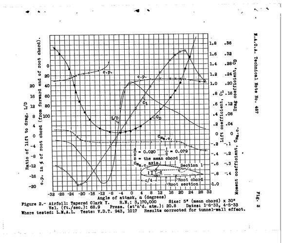
The airfoil chosen for the design is the Clark Y. A comparison of era airfoils is provided below. Designed in 1922 the airfoil has good a good CLmax/CDmin value, minimal Cm for varying angels of attack, and has relatively benign stall characteristics. It also has sufficient volume for the design of internal structural components and there is plenty of data on the airfoils characteristics available.
 

Attachments

  • Clark Y NACA.jpg
    Clark Y NACA.jpg
    266.6 KB · Views: 67
  • Era airfoils.png
    Era airfoils.png
    743.2 KB · Views: 96
Last edited:
Initial weights, moments and CG provided below. CG location in reference to the MAC or Mean Aerodynamic Chord is the station of the c.g. location minus leading edge station divided by the MAC (or the average wing chord). In this case its (95.99 in -54.00 in)/75.96 in, or 0.55. This 55% MAC is too far rearward and should be between 15% to 28% MAC as for most aircraft. This initial weight estimate may not be very accurate as the airframe weights and other aircraft systems were left out of the CG calculation for the first cursory examination of the weights and moments. A reiteration of the design as additional component weights are included will be needed to refine the design.
 

Attachments

  • Initial Weights and Moments.jpg
    Initial Weights and Moments.jpg
    1.4 MB · Views: 96
Last edited:
While considering the airframe for this design I thought that the technology of manufacturing should also stay in the time period of 1920-1923, the same period considered for the Type I designation. At that time metals were used in some aircraft construction, however metal was not widely adopted by most manufacturers until the 1930s. Welded steel tube construction was becoming more popular in fuselage construction while using wood (spruce) spars and ribs with fabric covering. I included a video here that shows the construction of wing components in the early 1920s. Not much different than a few years earlier in WWI.

View: https://www.youtube.com/watch?v=XUx5Ub6x2zI&t=288s
 
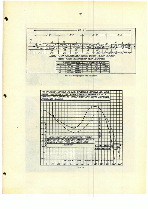
Considering the Air Service Information Circular No. 556 from McCook Field Comparison of Tests on Experimental 15 Inch Metal Spars and 11 Foot Chord Metal Ribs, the data from the Boeing design had the highest strength to weight ratio demonstrated during tests. The Aeromarine rib (Fig. 52) also succeeded in reaching 110% of its design load. I made a hand drawn sketch of how these two components would integrate.
 

Attachments

  • Spar Rib Sketch with caps.jpg
    Spar Rib Sketch with caps.jpg
    415.9 KB · Views: 78
  • Experimental Spar.jpg
    Experimental Spar.jpg
    974.7 KB · Views: 53
  • Spar Test.jpg
    Spar Test.jpg
    1.4 MB · Views: 52
  • Figure 52 Wing Rib.jpg
    Figure 52 Wing Rib.jpg
    1.1 MB · Views: 74
Last edited:
A couple of refined sketches. The wing was repositioned about 9 inches reward to align the spars with the airframe (which also puts the Center of Pressure in to a better positional relation to the aircraft's Center of Gravity). I covered the inboard section of the wing with corrugated duraluminum, which stresses the skin over the wing fuel tanks as internal bracing was not available. I used flying and landing wires instead of struts. The cantilever design was not popular during the era without large airfoils and corrugated metal covering so a wire braced design would be a good compromise. I liked the Boeing P-26 gear design so I designed a small set of gear similar to the Peashooter that would have come a few years later.
 

Attachments

  • Refined Profile Sketch.jpg
    Refined Profile Sketch.jpg
    352.6 KB · Views: 81
  • Refined Top View Sketch.jpg
    Refined Top View Sketch.jpg
    361 KB · Views: 99
Last edited:
A panel layout that would be adequate for this aircraft would be a small panel that would allow for the Browning .30 caliber guns to fit alongside the panel for the pilot to access and charge the weapon. The Boeing F4B-4 and the Curtiss P-12E have similar panels.
 

Attachments

  • Panel Design Selection.jpg
    Panel Design Selection.jpg
    38.9 KB · Views: 85
  • Cockpit Sketch.jpg
    Cockpit Sketch.jpg
    453.4 KB · Views: 71
Last edited:
I think we can be more adventurous because we have seen things that they couldn't think of yet.
I would go for a flying wing or blended body with a pusher-design. Closed cockpit and (primitive) retractable landinggear. Why not 2 engines? P-38 had two engines and was a superior fighter design. Or two engines in line driving 1 propeller. Metal for structural parts and cloth for control-surfaces, the extra drag should be minimal. How far could we push the modern ideas in 1919?
 
I agree, there are a number of things that could have been done to improve performance that was coming a few years later (1930s, such as retractable gear, all metal monoplane designs, supercharging), which followed the 1919-1923 era of the PW specification. I created the exercise as a challenge to design an aircraft with the constraints that may have been placed on the designers at the time without the benefit of future knowledge (i.e. knowledge of materials, processes, and design techniques). The monoplane design presented was a departure from convention in the biplane era of the early 1920s with a steel tube fuselage, which was cutting-edge at the time, and an introduction of some metal around the engine (to reduce fire hazards) and at the aircraft wing root for increased strength. All metal aircraft were being developed (Fokker, Stout, and Ford), however most of these designs used corrugated metal skin that increased the wetted surface area of the aircraft an increased its drag.

I think that your idea is very interesting and I will pursue another, advanced concept design, that tries to press the edge of 1919-1923 technology!
 
Last edited:
Speedco PW-10 is a good start and certainly in line withy 1920s fashion.
... cough ... cough ... art deco ... cough ... cough

That narrow instrument panel is just a narrow version of the basic 6 instrument panel adopted by the RAF, so easy for pilots transitioning to the new airplane. Definitely want to group all the engine instruments and controls on the left side of the cockpit.
I would prefer a Hispano Suiza 8Cb V-8 engine producing 180 hp. as installed in some SPAD XII. The propeller speed reduction unit would raise the thrust line, allowing for shorter landing gear legs. To eliminate the worst complaints about the SPAD XII installation, mount the motor cannon slightly farther forward and install a fume extractor or extended blast tube to vent cordite fumes overboard.

The 37 mm motor-cannon (ala. SPAD XII) was overkill against wood and fabric airframes, but a 20 mm or even 12.7 mm (Browning .50 caliber) firing through the prop hub would be an advantage against 1930s vintage all metal airplanes. You could still install a pair of .30 caliber (8 mm) machine guns in the cowl or outer wing panels.

Curved wing tip bows were fashionable back then and were structurally the lightest, however, modern learning tells us that swept wing tips are more efficient because they force wing tip vortexes farther outboard (see the Schumann wings currently fashionable on competition sailplanes and Reno Ari Racers).
Finally, I would like to see a taller vertical fin with a higher aspect ratio. This would lift it above the worst turbulance created by the open cockpit. You would probably still need a dorsal fin to maintain directional stability. Might also need a ventral strake to improve spin recovery.
 
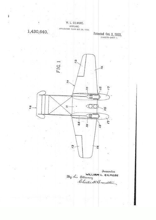
Some interesting ideas that were patented between 1920 and 1923. One for a high speed aircraft design and the other for a twin engine configuration (but more on the scale of a Light Day Bomber). Also, a concept design for a retractable landing gear.
 

Attachments

  • scan_20211123220331.jpg
    scan_20211123220331.jpg
    381.7 KB · Views: 75
  • scan_20211123220334.jpg
    scan_20211123220334.jpg
    435.5 KB · Views: 61
  • scan_20211123220337.jpg
    scan_20211123220337.jpg
    308.4 KB · Views: 58
  • scan_20211123220340.jpg
    scan_20211123220340.jpg
    405.6 KB · Views: 59
  • scan_20211123220343.jpg
    scan_20211123220343.jpg
    406.6 KB · Views: 53
  • scan_20211123220345.jpg
    scan_20211123220345.jpg
    486.9 KB · Views: 64
Here's an advanced concept based on the E. V. Boiler patent, but looks a lot like a Payen Pa.22. Carries an inverted 425 Hp Curtiss D-12. Two .50 cal propeller synchronized MG, with a Curtiss Reed metal propeller design. Water cooled with an underslung radiator and fixed under carriage. A wooden airframe may be sufficient, but the wing loading maybe very high. I'll work out the component weights and CG. The design should be commensurate with other tandem wing concepts to work out the flight controls and issues of stability. The second aircraft is slightly larger with a 1920 Dayton Wright RB-1 type retractable landing gear.
 

Attachments

  • PW11 Sketch.jpg
    PW11 Sketch.jpg
    249.3 KB · Views: 64
  • Larger with Retracts.jpg
    Larger with Retracts.jpg
    383.8 KB · Views: 67
Last edited:
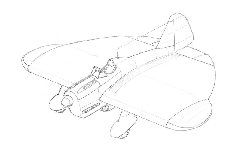
Here is an incomplete sketch of the aircraft. For fun, just looking at branding, I nicknamed the aircraft the Westerner, which gives it a western theme as I looked at movies that would have possibly influenced the naming of the aircraft (similar to the F-22 Raptor and the movie Jurassic Park). Western movies were very popular in the 1920s-1930s. I also looked at the names Mohican, Shawnee, Deringer, and Colt. As manufacturers had naming themes, e.g. McDonnell Douglas had ghosts and spiritual themes, Grumman had its cats, and Lockheed had celestial themes I though this one could be the Wild West.
 

Attachments

  • Westerner1.jpg
    Westerner1.jpg
    1.2 MB · Views: 83
Last edited:
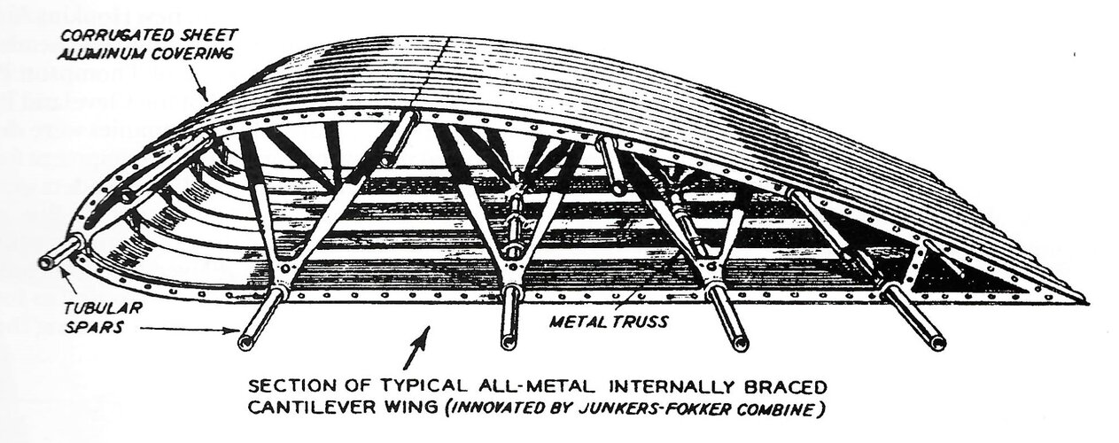
Inboard wing section for the PW-10 is corrugated duralumin metal to strengthen wing root. An example of this structure is provided. Also, a basic layout of the flight control system.
 

Attachments

  • 1920s Metal Wing Section.jpg
    1920s Metal Wing Section.jpg
    517.8 KB · Views: 79
  • PW Flight Control.jpg
    PW Flight Control.jpg
    132.5 KB · Views: 98
I built a model (by smashing some kits together (BTW I'm not very good at model making)) of a notional PW-10 to look at the possible gun configurations (top or side fuselage mounted or wing mounted), bomb racks (fuselage or wings), and even the location of a K-3A camera for a reconnaissance variant. I wanted to see the effects of landing gear spacing on the wing structure (mounting locations with the inboard aluminum wing) and possible external rigging options (e.g. struts, wire bracing, or none).

I think I've settled on top mounted twin .30 cal Browning machine guns with fixtures for an A-3 bomb rack under the fuselage. The tall headrest fairing was designed to help reduce the impact to the pilot during a roll over, however the buffeting on the tail surfaces (from what I read on the Boeing P-26A) and the limitation of rearward visibility makes me think that I may not include it in the final drawings. A Prouty type oxygen regulator (Type A-2) and oxygen cylinder system is designed into the aircraft and installed behind the pilots seat with a radio set (SCR-134). The location of a K-3A camera (or other units) were considered for follow-on variants, but its weight would require it to be mounted immediately behind the pilot, displacing radios.
 

Attachments

  • PW10 Concept Model.jpg
    PW10 Concept Model.jpg
    1.7 MB · Views: 93
Dear Dynoman,
You can keep that height of headrest as long as you extend it towards the fin. If you keep the top edge of the headrest sharp, it will add to yaw stability.
I suspect that Boeing's Peashooter suffered from poor airflow out of the cowling and the steep headrest just complicated the turbulence.
 

Similar threads

Please donate to support the forum.

Back
Top Bottom