ChuckAnderson

ACCESS: Confidential
Joined
10 May 2006
Messages
188
Reaction score
42
Hi Everyone!

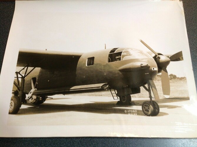
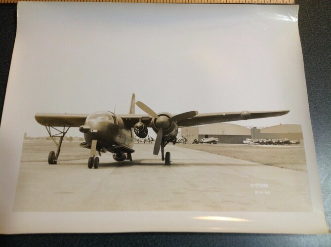
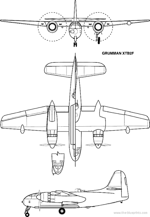
Presented here are illustrations of a WW2 Grumman design for a two-engine torpedo plane/attack bomber for the USN. A mock-up was built of this aircraft, but it proceeded no further

It was the Grumman XTB2F-1 and had the Grumman company's designation of Design 55.

It was to be very heavily-armed and the wings were to fold for stowage aboard an aircraft carrier.

Chuck
 

Attachments

  • TB2F-1.JPG
    TB2F-1.JPG
    53.1 KB · Views: 1,499
Here's my own sum-up of this aircraft from my archives:

GRUMMAN TB2F

In 1942, the US Bureau of Aeronautics asked Grumman to design a possible successor to the company's highly successful Avenger torpedo bomber. Further discussions led Grumman to initiate the development of TB2F in 1944. The initial concept was for a multi-seat torpedo bomber with twin 2,100 hp Pratt & Whitney R-2800-22 Double Wasp engines. Unfortunately, the XTB2F-1 proved too ambitious, as the design was simply too big and heavy to be operated from other than Midway-class carriers. Only a mockup was constructed and the XTB2F-1 was cancelled in January 1945. Ten 12.7 mm machine guns and a 3,600 kg bomb load.

Data for XTB2F-1: wingspan: 22.56 m; length: 15.85 m; height: 6.45 m; empty weight: 10,200 kg; max. weight: 20,410 kg; speed: 544 km/h; ceiling: 9,630 m; range: 5,960 km.
 
As a first approximation, I'd guess it to be something of a half-way point between the F7F and the S2F. As I remember, it shared much of its wing and nacelle structure with the F7F.
 
I wonder what influence this design had on the Grumman S2F/S-2 Tracker. The configuration is very similar.

You're right Sentinel!

More than 10 years ago there was a comprehensive article about the G-55 on a French aviation magazine (It was not Le Fana). At that time I had no money enough to buy it because I was at the University. Might be our french comrades can give a help ;)
 
From the NHC files:

ARMY AIR FORCES
MATERIEL COMMAND
ENGINEERING DIVISION
MEMORANDUM REPORT ON

DATE: 22 May 1944

Subject: Mock-Up Inspection of Navy XTB2F-1 Airplane
Section: Technical Staff.
Serial No. ENG-50-1049

A. Purpose

1, To report results of mock-up inspection of the Navy XTB2F-1 airplane being built by the Grumman Aircraft Engineering Corporation, Bethpage, L.I., N.Y.

B. Factual Data

2. Personnel comprising the Mock-up Committee are as follows:

Col. C. L. Fike
USMC
Experiments and Developments

Coradr. W. W. Hollister
ÜSN
VTB Class Deck

Lt. W. T. Estabrook
USNR
VTB Class Deck

Comdr. J. F. Quilter
USN
Ships Installations

Mr. W. Z. Frisbie


Design

Comdr. E. R. Sanders
ÜSN
Military Requirements

Lt. Comdr. R. F. Farrington
USN
Military Requirements

Lt. Comdr. V. R. Richardson
USNR
Radio and Radar

Capt. R. L. Dickey
USMC
Radio and Radar

Lt. Coradr. W. T. Sutherland
USN
Armaments

Lt. W. J. Harris, Jr.
USNR
Armor Plate

Lt. Comdr. A. P. Coffin
USN
Bureau of Ordnance

Lt. Harris G. Beck, Jr.
USNR
Bureau of Ordnance

Lt. Comdr. F. A. Wyekoff
Turrets

Lt. Gordon Fritch
USNR
Bomb Bay

Lt. D. J. Hardy
USN
Instruments

Lt. J. Welch, Jr.
USNR
Rockets

Ensign J. B. Kemmer
USNR
Photography

Lt. Comdr. Herring
Maintenance

Ensign CP. Farrel
Maintenance

Lt. Comdr. R. K. West
USNR
Equipment & Materials

Lt. Comdr. J. A. Fergusen
USN
Flight Test, Patuxent River

Mr. G. U. Deits
Specifications

Mr. W. W. Rust
Power Plants

Lt. W. P. Montgomery
USNR
Structures

Lt. W. R. Wilson
USN
BAGR, Eastern District

Comdr. Haase
BAR, General Inspector

Lt. Comdr. W. Gerstell
BAR, Armament

Lt. Comdr. F. H. E. Hopkins
RN
British Representative

Lt. J. P. M. Reid
RNR
British Representative

Lt. Col. J. H. Sams
USA
Army Representative

Capt. G. D. Colchagoff
USA
Army Representative

3. In addition to the Above, Grumman representatives were as follows:

Arthur Kock
Project Engineer

Robert Hall
Asst. Chief, Engineer

Arthur Frank
Asst. Project Engineer

William Wange
Power Plant

Herbert Gnutzman
Armament Bomb Bay

Clarence Prossley
Turrets

Bruce Smith
Cockpit arrangement & fixed equipment

Oscar Olson
Electrical & General Equipment Engineering

William Schwendler
Chief Engineer

George Titterton
Asst. Production Chief.

4. The mock-up of this airplane was very complete and wherever possible the actual item was installed.

5. Grumman Representatives did an excellent job of keeping the mock-up conference running smoothly and were very efficient in making recommended mock-up changes over night in time for the next day's inspection.

6. Navy personnel were very courteous to the Materiel Command representative and willingly furnished engineering data and information in answer to all questions asked.

7. This airplane project is a most ambitious one, for the Navy and for Grumman, who have never attempted an airplane of this large size before.

It is an outgrowth of experience gained from the Grumman TBF with an effort to increase range, bomb load and effectiveness of all armament components.

8. The XTB2F-1 is to be used for horizontal, glide (up to 50°), masthead and torpedo bombing, mine laying, sub and long rang patrol.

9. A more detailed description of this airplane is contained in Exhibit "A"

C. Conclusions.

1. The performance of the subject airplane falls short of the minimum performance now desired by Army Air Forces although it may prove to be remarkable as a carrier based bomber.

2. Inasmuch as Grumman expects this airplane to see combat in about two years, airplanes that the AAF now has under development will be in production then and will far out perform the subject airplane in all of its functions.

D. Recommendations

1. It is recommended that the experimental progress of the subject airplane be followed and flight test performance be obtained for comparison with AAF aircraft.

Prepared by
G. D. Colchagoff. Capt. A.C.

Approved by
H. Z. Bogert. Colonel, A.C.
Chief. Tech.Staff

Approved by
F. O. CARROLL. Brig. Gen. U.S.A.
Chief Engineering Division

- - - - - - - - - - - - - - - - - - - - - - - - - - - - - - - - - - - - - - - - - - - - - - - - - - - - - - - - - - -

Distribution:
Bureau of Aeronautics
Bureau of Aeronautics Gen Rep.
Materiel Command Liaison Office at the Bu. of Aero.
AC/AS, MM&D, Devel. Engr. Br. (3)
Production Eng. Sec.
Bombardment Bu. Tech. Staff.

Eng. Div. Memo. Rep. ENG-50-1049
22 May 1944

EXHIBIT "A"

1. General

A. The Bureau of Aeronautics has contracted with the Grumman Aircraft Engineering Corporation, Bethpage, Long Island, New York, for the construction of two (2) XTB2F-1 experimental airplanes, the first of which should be ready for initial flight late in 1945. Production models are expected to be started in the summer of 1945.

b. The XTB2F-1 Airplane is a twin-engine, 4-place torpedo-bomber landplane for use ashore and aboard aircraft carriers as a torpedo plane, glide or skip bomber, or as a scout airplane.

e. The airplane shall take off from the deck of an aircraft carrier of the CVB Type with or without the aid of a catapult and land on a carrier deck in an arresting gear or on an ordinary landing field.

2. Description

a. The XTB2F-1 is a conventional high wing airplane somewhat similar to the B-26 except that the requirement that this airplane be carrier based has resulted in short thick wings and fuselage.

b. The wing span is 74 feet, chord is 12.5 feet at the root and the area is 777 square feet. The wing folds back and outboard so that the span is 36 feet. The hydraulically operated flaps are of the fixed hinge slotted type. The airfoil is of the NACA 23017 at the root and NACA 23011 at the tip. This airplane is designed for a 4 G yield and a 6 G ultimate.

e. The empennage has conventional symmetrical tail surfaces. The height of the vertical stabilizer is normally 19 feet so in order to have proper clearance for stowage below decks in the carrier hangers, the nose wheel strut will be extended by means of a hydraulic accumulator to lower the tail two feet.

d. The landing gear is of the tricycle type except that there are dual nose wheels on the nose wheel strut. The main wheel thread is 23 feet.

e. The fuselage window arrangement for the pilot is similar to the C-46 and has excellent visibility, the mock-up committee recommended even more window panels overhead. The cockpit arrangement is identical with the Navy single pilot type now used in service except that a wheel type control will be used and there will be a Pioneer type A-10 Auto-Pilot.

f. The normal crew will consist of four members; pilot, radio and radar operator who will sit next to the pilot, and top turret and bottom turret operators. Each will have individual para-life rafts.

g. A passage way over the bomb bay will connect the fore and aft decks. This aft deck will contain only the top and bottom turrets.

3. Power Plant

a. The XTB2F-1 Airplane is powered by two Pratt & Whitney Model R-2800-22 single stage two-speed, right hand rotation engines geared 0.4-5:1. There are no provisions for War Emergency Power. The Military Power for each engine is 2100 BHP at 2800 RPM.

b. The engine ring cowl, cowl flap, dishpan cowl and exhaust system are identical to that of the F7F-4. Both right and left engines and their mounts are interchangeable.

c. The propeller to be used in conjunction with this engine is the 3-blade, Curtiss electric 14.'-0" with No. 830 blades.

4. Armament

a. The XTB2F-1 Airplane will have six forward firing fixed .50 caliber machine guns and two turrets.

b. Two .50 caliber guns will be located in the left side of the fuselage under the pilot compartment. Each gun will have 400 rounds of ammunition.

c. Four .50 caliber guns will be located in the wing, two on each side of the fuselage, with an alternate installation of either 20 millimeter or .60 caliber guns in place of the .50 caliber guns on the same mountings. The .50 caliber guns will have 400 rounds of ammunition each while the 20 millimeter and the .60 caliber guns will have 200 and 120 rounds of ammunition respectively per gun. All three installations would use the same size ammunition box.

d. There is an Emerson Modified Dumbo upper turret over the aft end of the bomb bay with two .50 caliber machine guns and 400 rounds per gun.

e. A standard Sperry A-13-A inhabited retractable lower turret behind the bomb bay contains two .50 caliber machine guns with 400 rounds each.

f. There will be provisions for both a 75 millimeter cannon and a Mark 15 optical bombsight on the right side of the pilot's deck. It is intended that only one of the two will be installed at any one time. Inasmuch as it is felt that the airplane will seldom be used for high altitude bombing, the 75 millimeter cannon will be the common installation.

g. The optical bombsight is being specified, but it is expected that a radar type bombsight will be used when it is available.

h. Pilot will fire the cannon and guide on radar operated cross hairs. The pilot's sighting will be done by a torpedo director radar type gunsight. For this purpose a standard Mark 8 with a tilting reflector will be used in conjunction with the 75 millimeter cannon Radar Ranging device.

i. The fourth crew member will sit next to the pilot to assist him on take offs and landings and operate the Radar Ranging device for the 75 millimeter cannon or the optical and eventually the radar bombsight, and also the other radio equipment.

j. In low level attacks the 75 millimeter cannon will be manually loaded by the ball turret operator with 12 rounds of ready ammunition.

k. The cone of fire of the flexible guns is such that upper turret fires 10° below the horizon on all sides except for the airplane's structure. The lower turret fires 8-1/2° up all around except for the fuselage structure. At V maximum the upper turret fires straight ahead while the lower turret fires 1-1/2° below the horizon.

l. In lieu of a drift sight both the optical bombsight and the lower turret with a built-in azimuth scale will be used.

m. Rocket provisions will be made several months prior to delivery of the first production airplane.

n. There will be a torpedo camera (F-46) and a gun camera, for the fixed guns in the nose. The upper and lower turrets will both have gun cameras.

o. Passive protection against .30 caliber gunfire is provided for the pilot, crew, oil tanks, and oil coolers. Provisions will be made for protection against .50 caliber gunfire.

5. Bomb Provisions

a. The XTB2F-1 airplane has an excellent bomb bay arrangement. The mock-up was very complete and all the various bomb, mine, and torpedo loads were simulated by full scale models. The bomb bay will normally have 20 shackle stations, 9 on each side and 2 in the roof on the center line. For 100 pound bombs, there will be an alternate installation 36 shackle stations by the addition of 3 complete center bay sections.

b. The shackles will be placed so that there is no possibility of a bomb, torpedo or mine striking any part of the airplane structure after release during horizontal bombing or during release in glide bombing angles up to 50 degrees.

c. The bomb and mine loads to be carried are as follows:

1 x 4000# Class bomb
or
24 x 100# fragmentation bomb clusters
or
4 x 2000# Class bombs
or
4 x 650# Depth Bombs
or
4 x1600# Class Bombs,
or
10 x 350# Depth Bombs
or
4 x1000# Class Bombs,
or
10 x 325# Depth Bombs
or
10 x 500# Class Bombs,
or
2 x 2000# Class Mines
or
10 x 500# Incendiary Bomb Clusters
or
4 x 1000# Class Mines.
or
36 x 100# Class bombs,
or
Either one or two 2084# torpedoes can be carried.

d. The contractor stated that it is possible to carry 10 - 1600# bombs, It will be possible to carry one 2000# class bomb in place of each of the two external wing tanks.

6. Weight

a. The XTB2F-1 Airplane is expected to fly normally at approximately 38,000#. This is as a torpedo bomber. This, and the other gross weight con ditions of the airplane, is expected to be increased as a result of the recommendations made by the Mock-Up Committee.

7. Fuel

a. The XTB2F-1 Airplane fuel tanks have the following capacities;

Main Wing tanks
Self-sealing cell
960 gallons

Two auxiliary droppable wing tanks
None
600 gallons

Total fuel capacity
1,560 gallons

8. Range and Radius of Action

a. The range of the XTB2F-1 Airplane with 1,560 gallons of fuel and 4 - 2000# bombs carried one half of the distance is 3050 miles.

b. Radius of Action estimated for the XTB2F-1 Airplane with 960 gallons of internal fuel.

(snip complicated table)

Radius of Action = 393 nautical miles or 452 miles.

Radius of Action estimated for the XTB2F-1 Airplane with 960 gallons of internal and 600 gallons of external fuel.


(snip complicated table)

Radius of Action - 722 nautical miles or 833 miles.

9. Performance

a. The following performance is estimated for a gross weight of 37,027 pounds and 960 gallons fuel:

High Speed at seal level, mil power (MPH).
309

High Speed at airplane crit. alt. (MPH)
331

Stalling Speed at sea level, full load, without power (MPH)
94.3

Rate of Climb at sea level rail, power (ft./min.)
2,230

Time to Climb - to 10.000 ft. alt. (Min)
5.5

to 20,000 ft. alt. (min)
13.3

Service Altitude (feet)
27,380

Endurance at 5000 ft. - at 60% high speed (hrs)
11.68

Maximum (hrs)
13.50

Maximum Range at 5000 ft. Alt. - with torpedoes or bombs carried 1/2 distance (miles)
2,020

Average Speed for maximum range (MPH)
170

Take-off distance - in calm (feet)
1,057


- - - - - - - - - - - - - - - - - - - - - - - - - - - - - - - - - - - - - - - - - - - - - - - - - - - - - - - - - - -

Aer-E-17-BTE
VTB2F1/F1-1, C16474

Confi - 16 Jun 1944

From: Chief, BuAer
To: BAR, Bethpage, L.I., New York
Subj: Model XTB2F-1 Airplane - Mock-Up Board Report
Encl.( (A) Two (2) copies of Mock-up Board Report. (HW)

1. Subject report is hereby forwarded as Enclosure (A). This report is for record purposes only as this project is being cancelled.

W. W. HOLLISTER
Comdr. U.S.N.
 
VTB2F1/Ar, Conf File
Navy Dept, BuAer, Wash 25, D.C.
VTB Designs Comments

Cancellation of the TB2F will undoubtedly establish a policy in BuAer which will limit the size of carrier aircraft to a maximum of 26,000 lbs gross weight. This weight sets a definite limit on range and bomb load. If high speed is paramount in a torpedo bomber, it is believed that a single seat, single engine, light plane should be developed. This desk considers that the TB2F is worth trying. A long range plane with a large bomb capacity capable of operating from a carrier should have some tactical advantages. In regard to the basic ltr the following comments are made:

a. Original plane was designed only for the CVB carriers. It must be noted that the TB2D is designed only for the CVB and CV9 carriers.

b. An plane with the bomb load capacity of TB2F, and resultant weight, that can make 310 mph is considered to have excellent performance. A B25 and B26 will not carry this load at this speed nor land on a carrier.

c. Present take-off distance of a TB1D is 480 feet in a 25 Knot wind. TB2D with 2 torpedoes is estimated to be 485 ft in 25 knot; the SB2C with 2 1000 lbs bomb is 670 ft in a 25 knot wind.

d. TB2D will spot about 6 planes per 100 ft. It is considered that the reason for building the larger carriers is to accommodate larger planes.

e. TB2D will also require jettisoning of bomb load if a landing on the carrier is necessary immediately after take-off.

f. A nose wheel extension may be required on the TB2D to obtain hangar clearance. Both Grumman and Douglas feel that they can satisfactorily accomplish this.

g. Clearances on carrier elevators are small on practically all carriers for all torpedo and dive bomber planes. Similar problems must be expected with F7F and the TB26.

In order to overcome the disadvantages listed in this memo, both range and bomb-load must be radically reduced. VTB feels that cancellation of the TB2F definitely commits the Navy to small short range carrier aircraft. Increasing horse power of present models will definitely result in increase take-off distance end weight. The TBM is now up to 18,000 lb and the only characteristics that can be improved is speed.

VTB recommends that new over-all dimensions and gross weights be established for the TB2F and Grumman be requested to investigate removal of weight to reach such figures. Since a majority of the objections to the TB2F listed in basic ltr apply almost equally to the TB2D, this desk is somewhat concerned the difficulties that may arise in carrier operations with this plane. Douglas Co. is at present manufacturing 3 different vertical tail configurations with following resultant tail heights over the deck:

A. - 17 feet
B - 18 ft 6 inch
C - 19 ft 6 inch

The final production tail will depend on flight tests of demonstration piece. Douglas feels that the 18' 6" height tail will be necessary to obtain satisfactory lateral stability. If this tail is required, nose wheel extension must be employed to reduce tail heights in the hangar. Ships Installations has indicated that this will be unsatisfactory aboard ship.

If the need for long range carrier torpedo bombers can be considered subordinate to ease of handling aboard ship, it is believed that both the TB2F and TB2D designs must be considered equally. Cancellation of one design jeopardizes the advisability of proceeding with other since identical problems are involved. The question now paramount is torpedo plane performance as compared to carrier handling facilities. Only small, light carrier type planes can be expeditiously handled on ship board.

W. W. Hollister.

- - - - - - - - - - - - - - - - - - - - - - - - - - - - - - - - - - - - - - - - - - - - - - - -

E & D Comment

Desirability of cancellation of TB2F depends on whether it is to be Navy policy to have a twin engine aircraft of maximum range and torpedo capacity which can be operated from the CVB class carriers. This airplane is admittedly a tight squeeze on CVB elevators and hangar deck. However, its size and weight cannot be appreciably reduced unless one torpedo is eliminated. Even in this case, if it is to remain a twin engine plane it's overall dimensions cannot be reduced enough to appreciably effect the deck spotting requirements.

Any thought that the F7F can be modified to produce a torpedo plane carrying one torpedo internally and still having same overall dimensions should be discarded. Such an airplane would be approx 49 ft long and thus not operable on CV elevators. Its spot would be practically the same as the TB2F.

It certainly does not appear that the TB2F would be desirable as part of the basic air group for CVB's. On the other hand it is believed that an alternate air group containing TB2F might be exceedingly useful for special purposes. In order to fully exploit all of the tactical capabilities of the CVB class it is believed that a moderate number of these planes should be built. Fike 5-22

- - - - - - - - - - - - - - - - - - - - - - - - - - - - - - - - - - - - - - - - - - - - - - - -

The TB2F can be operated from the CVB carrier. It would entail a reduced number of planes on both the flight and hangar decks and reduced speed of operation for the total complement (see Capt. Bolster's analysis attached*. However, this was known at the inception of the design. The only 2 adverse changes in characteristics since then have been (1) necessity for raising nose wheel in hangar (which should not be too difficult to do) and an increase of about 1000 lbs in weight empty due to provision for special equipment - 75 mm cannon, radar, extra overload guns, bomb sight, increase in armor plate provision.

For special missions this model would be capable of performing missions which no other plane can do. Therefore, it is believed that a limited number should be obtained.

In view of wide difference of opinion, it might be well to obtain the desires of the Fleet. If this is concurred in Engineering will draft, the letter stating impartially the pros and cons, getting Military Requirement's approval before its submission for signature.

The TB2D is in same boat. H. R. Oster. 5-26

- - - - - - - - - - - - - - - - - - - - - - - - - - - - - - - - - - - - - - - - - - - - - - - -

VTB2F1/Ar, Conf File
Aer-R-10-RFF, Memo, 20 May 44
From: Military Requirements.
To: Chief, BuAer.
Subj: Cancellation of XTB2F Project - Recommendation for.

1. Mock-up Board for the XTB2F convened at Grumman Aircraft Engineering Corporation 1 to 4 May. While the board was immediately concerned with the way in which the essentials of the mock-up conformed to the specification, there was much general discussion relative to the operational limits imposed by the weight and size of the model.

2. Military Requirements recommends that the XTB2F project be cancelled and that no further development of this model he undertaken.

(a) This plane because of its weight and size can only be used from CVB, and their weight and clearances make even this use appear impractical.

(b) In comparison with other types, the XTB2F is only slightly faster, 310 mph. as against 293 mph. for the TBY, and not up to the speeds of new design attack planes.

(c) The carrier take-off run is exceedingly long. Take off with 700 gallons (reduced fuel) is 449 feet, indicating an operational spot of 600 feet from the bow. Take-off with 960 gallons (full internal fuel) is 646 feet, indicating an operational spot of 725 feet from the bow.

(d) the large size of the plane greatly reduces the number of planes which can be carried per ship. Studies indicate that only 5 1/2 planes per 100 feet of flight deck can be accommodated, while current VTB types spot 10 to 12 planes per 100 feet of deck.

(e) The weight of the plane (35,000 lbs.) is greater than that for which the flight deck of the CVB is stressed (26,000 lbs.). An emergency landing immediately after take-off would require complete jettisoning of the bomb load which would still leave the plane at approximately 33,000 lbs.

(f) The height of the plane, 20' 1" over the tail, requires the use of unproven arrangement of a nose wheel extending device which lowers the tail to 17'. Handling in the hangar will be marginal, even on the CVB. Although the plane, 52'6" x 36.0' folded, will operate, unloaded only, on the two deck elevators, which are 54' x 46', it will not operate on the side elevator 54' x 34'.

Elevator operating strength:
26,000 lbs
46 seconds

Overload:
35,000 lbs
53 seconds

3. The advantages intended to be gained in this type were:

(a) Increased load and armament
(b) Increased rate of climb
(c) Increased range

Although the load and armament per plane is doubled, the number of planes that can be carried is less than one-half. It is considered that carrier types must maintain performance, as against range, equal or superior to other enemy types, both land and ship based. A carrier attack cannot be based on surprise alone. Surprise will no longer be achieved with enemy use of radar. Carrier success, then, must be based upon superior performance and local control of the air during raids, both over own carriers and over the target. Long range carrier types in which performance is sacrificed for range are inconsistent with this policy. For carrier VB and VTB, range equal only to that of VF is deemed necessary.

4. Military Requirements recommends that this project be cancelled for the following reasons:

(a) Marginal handling characteristics aboard ship.

(1) Overloads deck
(2) Overloads elevators
(3) Overloads catapults
(4) Increases maintenance difficulties
(5) Reduces utility and operational mobility
(6) Makes hangar clearance marginal

(b) Fewer planes per ship resulting in smaller bomb load per air group.
(c) Too much has been sacrificed for long range.

5. It is further believed that no useful purpose could be gained by building this plane as a Navy land-based plane.

(a) Its speed and range do not justify land-based use.
(b) Shore-based attack planes are not properly a function of the Navy.

R.F Farrington
Lt. Cmdr. USN

- - - - - - - - - - - - - - - - - - - - - - - - - - - - - - - - - - - - - - - - - - - - - - - -

Comment: Capt. Beakley has seen and agrees entirely with us. Farrington

- - - - - - - - - - - - - - - - - - - - - - - - - - - - - - - - - - - - - - - - - - - - - - - -

Your recommendation of 6/1 on routing sheet approved. Please proceed with cancellation of TB2F-1 project as outlined.

D. A. Ramsey

- - - - - - - - - - - - - - - - - - - - - - - - - - - - - - - - - - - - - - - - - - - - - - - -

Radar operator will have to also be radio operator and navigator. It is desirable also that he be capable of acting as relief pilot. The capacity for 2 aircraft torpedoes results in a bomb bay larger than that in A26, B25 or B26.

Fike 5-10

- - - - - - - - - - - - - - - - - - - - - - - - - - - - - - - - - - - - - - - - - - - - - - - -

I still consider XTB2F as to large and too heavy to be a satisfactory plane for CBV's. See my remarks in mockup report.
Quilton 5/12

- - - - - - - - - - - - - - - - - - - - - - - - - - - - - - - - - - - - - - - - - - - - - - - -

In my opinion we are wasting money, manpower and time to continue with TB2F. It should be stopped as of today.
Jones 5-26

- - - - - - - - - - - - - - - - - - - - - - - - - - - - - - - - - - - - - - - - - - - - - - - -

I concur heartily with comments of Military Requirements. Recommend immediate cancellation.
Cornwall 5-26

- - - - - - - - - - - - - - - - - - - - - - - - - - - - - - - - - - - - - - - - - - - - - - - -

Concur with above, for this war the CVB's will be tactically more useful operating CV9 based aircraft types.
Temple 5-29

- - - - - - - - - - - - - - - - - - - - - - - - - - - - - - - - - - - - - - - - - - - - - - - -

I recommend that the XTB2F-1 project be cancelled, but that the contract be not terminated until Grumman has opportunity to discuss alternative projects. This can be done by issuing a stop-work notice on XTB2F-1 planes, engineering data, etc.

Richardson 6-1-44.

- - - - - - - - - - - - - - - - - - - - - - - - - - - - - - - - - - - - - - - - - - - - - - - -

VTB2F1/Ar, Conf File
Aer-E-17-WWH,. Navy Dept, BuAer, Wash 25, D.C., 8 May 1944
From: VTB Design Branch
To: Director of Engineering
Subj: XTB2F Plane.

1. Mock-up board for inspection of XTB21 plane convened at Bethpage on 1 May and adjourned on 4 May. Major changes recommended by board were:

(1) Complete revision of the cockpit. Revision eliminates any future installation of dual controls since the engine controls were moved to pilot's left hand side.

(2) Modification of fuselage near aft end of bomb bay to install MK-15 optical bombsight.

(3) Total revision of armor plate protection for crew members.

(4) Increase in no. of crew members from 3 to 4, i.e. pilot, top gunner, bottom gunner and radar operator.

2. Considerable objections raised in regard to size and weight of this plane. Large CVB Class carriers will be provided with elevators 54 ft. long by 46 ft. wide. TB2F will have an overall length of 52' 6". Clearance in the hangar deck will be marginal since the nose wheel of the plane must be extended to reduce tail height to 17 ft. Elevator and flight deck capacities are for 26,000 lbs. while plane empty will weight 23,650 lbs. Catapults, Mk-5, are designed for 30,000 lbs. at 90 mph, and TB2F, with two torpedoes, will weigh 35,000 lbs. Although some of the dimensions and capacities are exceeded, it will not be impossible to operate this plane from CVB Class carriers.

3. Although there are many disadvantages to the size and weight of the TB2F for carrier operations, it is considered that some of these disadvantages in handling must be accepted in order to obtain the advantage of long range (775 mile combat radius) and ability to carry two torpedoes (4400 lbs bomb load). If these advantages are desirable and considered necessary by the fleet, the size and weight of the TB2F must be accepted. It is not believed possible to reduce the size or weight of such an airplane without drastically reducing range, or eliminating one torpedo.

W. W. Hollister, Cmdr USN

- - - - - - - - - - - - - - - - - - - - - - - - - - - - - - - - - - - - - - - - - - - - - - - -

CVB41/VV, NAVY DEPT, Confi May 24, 1944

Subj: XTB2F - CVB41 Spotting Study Take-off Runs in a 25 kn wind (Calculated – no safety factor)

XTB2F-1
34515# - 449 ft
37027# - 546 ft
45070# - 942 ft

Airplane cannot be flown off in the maximum overload (45070#) from a CVB Class Carrier; it can be catapulted in a 35 kt. wind.

Hanger deck spot = 33 (Assuming 17'0" overall height)

Flight Deck Spots = 20 (with 1 torpedo at 34515#) This allows for a 560 ft T.O. run, 900 gals T.Complement 35 (including 25% safety factor)

Landing Spot - 20 TB2F's allows a barrier penetration of 116 ft through B6a.
Landing Spot - 24 TB2F's allows a barrier penetration of 80 ft through B5a

Catapult Conditions:

Catapult-operations

Hangar Deck 22
Flight Deck 24
Total 46

Catapult-Ferry

Hangar Deck 22
Flight Deck 41
Total 63

This permits both catapults to be clear for initial launching

Hangar Deck 22
Flight Deck 44
Total 66

This permits use of only one catapult until 3 planes have been launched.

C.M. Bolster

- - - - - - - - - - - - - - - - - - - - - - - - - - - - - - - - - - - - - - - - - - - - - - - -

COMMENT:

The CVB, being larger than the CV; CVL and CVE has a larger turning radius and is in general less maneuverable. The greater size makes it an easier bombing and torpedo target. Not withstanding its larger flight deck and hangar deck, it has only one take-off area and one landing area. Consequently group take-off and landing time will be greater in proportion to the greater plane capacity. The one outstanding tactical characteristic which the CVB has which, none of the smaller carriers have is its ability to handle larger aircraft. The TB2F is an obvious attempt to provide something comparable to the B25 and B26 which can be operated from a CVB. The necessary lower landing speed and shorter take off make it actually larger wing area than either of B25 or B26. The size of the plane cannot be appreciably reduced without reduction of bomb bay size to a point which reduce torpedo capacity from 2 to 1, Such a change puts it in the class with TBF (which will still be must smaller). The size of the TB2F has not grown since its inception. Neither has the weight except for the overload condition intended for shore based operation. Admittedly it cannot be handled with ease from a CVB but it can be handled. I believe that if the tactical conception of the CVB is sound it is considered that the TB2F is sound.

Fike 5-16
 
VTB2F1/F1-1 Conf

Aer-E-17-WTE, VTB2F1/F1-1, CO9345
Confi 11 Apr 1944
From: Chief, BuAer
To: Commanding Officer, NAS, Patuxent liver, Maryland
Subj: XTB2F-1 - Mock-up Inspection of.

1. It is proposed to convene subject mock-up at the Grumman Aircraft Engineering Corp, Bethpage, L.I., N.Y., during period approx. May 1-4.

2. In effort to facilitate and expedite the work of Mock-up Board, it is desirous that the representation of the NAS be maintained at a minimum. It is requested that this Bureau be furnished the names of the representatives of

the NAS who will attend subject mock-up, and whether or not transportation is desired.

C. L. Fike, Col., USMC

Aer-E-17-WTE, VTB2F1/F1-1, 3126563
Confi. 7 Apr 1944
From: Chief of BuAer.
To: Recorder of Sub-Committe on Standarization of Joint Aircraft Committee.
Ref: (a) JAC SCS Report #1, Case #3000 of Sept. 15,1942.

1. In accordance with ref. (a) notification is hereby given that subj. inspection will be held at the Grumman Aircraft Engr. Corp. Bethpage, L.I.,N.Y. during the period approx. 1-4 May 1944.

2. The XTB2F-1 model has been designed as a twin engine, single tail, high wing carrier type airplane. It combines the functions of a torpedo plane, horizontal bomber and scout, having a range of approx. 1500 miles with normal load of 2 torpedoes. The airplane has also been designed to carry a 75 mm cannon and a bomb load of approx. 10,000 lbs. The maximum gross weight of subj. airplane, in overload condition, is approximately 45,000 lbs.

No allocation of the subject model have been made to services other than the Parent Service, the U.S. Navy.

3. In order to expedite the work of the mock-up Board, it is requested that representation of Advisory Services be maintained at a minimum. It is requested that this Bureau be furnished the names of the representatives of the Advisory Service who will attend subject Mock-up and whether or not transportation is desired.

C. L. FIKE Col., USMC
 
Interesting info. Any idea why it's from the Army Air Forces tho?


RyanCrierie said:
From the NHC files:

Edit: It is not necessary to quote quadrillion characters long post.
 
Thanks for all this. Not often do you get such detail for a 'neverwere'
 
pometablava said:
this plane, remember me the S-2 Tracker of '50 years , could be exist a connection with it ?

You're right, the S-2 was a derivative design from Model 55

Well, a family resemblance... it had different engines, wings, fuselage, etc. and 30% lower gross weight.
 

Attachments

  • S2F 3View.jpg
    S2F 3View.jpg
    164 KB · Views: 807
Well, a family resemblance... it had different engines, wings, fuselage, etc. and 30% lower gross weight.

Er...well I read Grumman used Model G-55 to develop the S-2. Possibly a very early iteration had more in common than the series produced item. ::)
 
Used Tommy's drawing of the TB2F as a basis; and stole some bits from some high resolution drawings of B-24s on the internet (for the turrets, since it used the same turrets IIRC as the B-24).

I did the colorization and drawing so that I could put the TB2F into War in the Pacific: Admiral's Edition.
 

Attachments

  • TB2F Colored.png
    TB2F Colored.png
    139.8 KB · Views: 905
ACResearcher said:
Here is a copy of the Model 55 T2BF drawing I did for Tony Buttler and my book American Secret Projects, 1937-1945.

I hope you find it of interest.

AlanG

Nice artwork per your usual high standard Alan, thanks for sharing it.

bill
 
Thanks, Bill!

So nice of you to say so. It always makes it easier to share this stuff when it has already appeared in print. I have dozens of drawings of fairly cool stuff that I should probably share here just for the sheer joy of it.

Speaking of which, if you have any drawings you'd like redone, send them on up. I used drawing time as therapy when taking a break from sorting through a few hundred thousand pages of documents - and about 1.5 million photos, too!

Thanks again.

AlanG
 
RyanC has added some interesting documentation and history (Thank You!),
Alan a helpful general arrangement I have a few images from NARA II Record
Group 72-AC-100G to share of the mock-up that will hopefully add to your
understanding of the design.

bill
 

Attachments

  • 72-AC-100G-14-XBT2F-1-Mock-up-19440611.jpg
    72-AC-100G-14-XBT2F-1-Mock-up-19440611.jpg
    161 KB · Views: 283
  • 72-AC-100G-13-XBT2F-1-Mock-up-19440611.jpg
    72-AC-100G-13-XBT2F-1-Mock-up-19440611.jpg
    164.1 KB · Views: 243
  • 72-AC-100G-12-XBT2F-1-Mock-up-19440611.jpg
    72-AC-100G-12-XBT2F-1-Mock-up-19440611.jpg
    164.5 KB · Views: 221
  • 72-AC-100G-11-XBT2F-1-Mock-up-19440611.jpg
    72-AC-100G-11-XBT2F-1-Mock-up-19440611.jpg
    197.6 KB · Views: 206
  • 72-AC-100G-10-XBT2F-1-Mock-up-19440611.jpg
    72-AC-100G-10-XBT2F-1-Mock-up-19440611.jpg
    195.7 KB · Views: 210
  • 72-AC-100G-09-XBT2F-1-Mock-up-19440611.jpg
    72-AC-100G-09-XBT2F-1-Mock-up-19440611.jpg
    166.4 KB · Views: 207
  • 72-AC-100G-08-XBT2F-1-Mock-up-19440611.jpg
    72-AC-100G-08-XBT2F-1-Mock-up-19440611.jpg
    163.4 KB · Views: 210
  • 72-AC-100G-06-XBT2F-1-Mock-up-19440611.jpg
    72-AC-100G-06-XBT2F-1-Mock-up-19440611.jpg
    158.5 KB · Views: 199
  • 72-AC-100G-05-XBT2F-1-Mock-up-19440611.jpg
    72-AC-100G-05-XBT2F-1-Mock-up-19440611.jpg
    160.2 KB · Views: 267
  • 72-AC-100G-02-XBT2F-1-Mock-up-19440611.jpg
    72-AC-100G-02-XBT2F-1-Mock-up-19440611.jpg
    157.9 KB · Views: 267
Some additional details.....
 

Attachments

  • 72-AC-100G-55-XBT2F-1-Mock-up-19440611.jpg
    72-AC-100G-55-XBT2F-1-Mock-up-19440611.jpg
    174 KB · Views: 226
  • 72-AC-100G-51-XBT2F-1-Mock-up-19440611.jpg
    72-AC-100G-51-XBT2F-1-Mock-up-19440611.jpg
    171.8 KB · Views: 181
  • 72-AC-100G-37-XBT2F-1-Mock-up-19440611.jpg
    72-AC-100G-37-XBT2F-1-Mock-up-19440611.jpg
    151 KB · Views: 169
  • 72-AC-100G-20-XBT2F-1-Mock-up-19440611.jpg
    72-AC-100G-20-XBT2F-1-Mock-up-19440611.jpg
    183.7 KB · Views: 158
  • 72-AC-100G-19-XBT2F-1-Mock-up-19440611.jpg
    72-AC-100G-19-XBT2F-1-Mock-up-19440611.jpg
    195.3 KB · Views: 163
  • 72-AC-100G-18-XBT2F-1-Mock-up-19440611.jpg
    72-AC-100G-18-XBT2F-1-Mock-up-19440611.jpg
    197 KB · Views: 169
  • 72-AC-100G-17-XBT2F-1-Mock-up-19440611.jpg
    72-AC-100G-17-XBT2F-1-Mock-up-19440611.jpg
    203.6 KB · Views: 167
  • 72-AC-100G-16-XBT2F-1-Mock-up-19440611.jpg
    72-AC-100G-16-XBT2F-1-Mock-up-19440611.jpg
    150.7 KB · Views: 173
  • 72-AC-100G-15-XBT2F-1-Mock-up-19440611.jpg
    72-AC-100G-15-XBT2F-1-Mock-up-19440611.jpg
    165.8 KB · Views: 173
I remembered it was a Grumman design, so I grabbed Grumman Aircraft since 1929 by René Francillon, Putnam. Found the XTBF2F-1 in Appendix B. Fed XTBF2F-1 to the forum-search. Easy-peasy.
 
This looks like the Grumman XTB2F replacement for the TBF Avenger.
Of course!
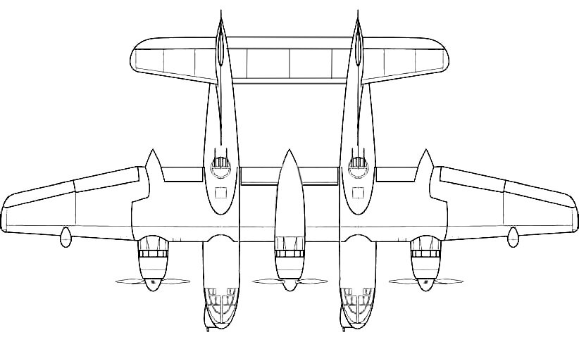
This mock-up clearly shows us new design features: asymmetric layout, shortened right wing (perhaps for easier stowage on carrier), single engine (mounted on the left wing), single auxiliary tank and radar - both on the single wing. Unusual solution, perhaps, inspired by Blohm&Voss projects :cool:
 
Couldn't we get back to more serious things ! ;)
It would be nice if this thread could be used for all similar unidentified aircraft searches ?
 
After identification, any information in threads like this
- is added to existing threads if the subject has been covered before
- stays in its own, renamed thread if the subject has not been covered before

A separate thread for unidentified items is likely to be extremely messy.
 

Please donate to support the forum.

Back
Top Bottom