Creating your own scale drawings: How to and best tools

500 Fan

ACCESS: Confidential
Joined
16 July 2010
Messages
97
Reaction score
44
Hi. I am currently researching the history of a particular helicopter, in particular the history of the various prototype and test variants of this helicopter. My initial plan was to write a book on this topic and publish it myself but for a number of reasons, this now won't be possible. I am still pushing on with my research and it will end up going into a book format as well as possibly ending up on a few websites as a PDF. I am lucky enough to have sourced plenty of useful photos for my project but one area that will enhance my final document will be accurate scale drawings. I estimate that I will need between 10 and 20 different sets of 3-view drawings, all variations of the same basic aircraft. The purpose of the drawings will be to illustrate the unique configuration of a particular aircraft as opposed to serving as highly detailed technical drawings. Every rivet will not necessarily be depicted in my planned drawings but at the same time, I want the overall drawings to be true to the original in outline and basic detail. I have two options open to me; commission an artist to draw the desired drawings or figure out a way to create the drawings myself. I would like to go for the second option, if at all possible, even though I have no experience of creating any kind of drawings. And so my questions are;


How do I go about learning to draw accurate, 3-view, scale drawings of my chosen subject?


Is it something you can learn by yourself using some kind of manual or will it require attending classes?


Is it a reasonable expectation to believe that it might be possible to learn how to draw scale drawings in just 12 months or so?


What option is best for the novice, learning to draw by hand or use some kind of computer graphics programme (given that I am not exactly a computer whiz)?


Thanks for any assistance or advice anyone can offer.

500 Fan.
 
500 Fan said:
I have two options open to me; commission an artist to draw the desired drawings or figure out a way to create the drawings myself. I would like to go for the second option, if at all possible, even though I have no experience of creating any kind of drawings.

The first question you have to deal with in this situation is whether it's worth it to do the drawings yourself. Yes, if you commission an artist/draftsman to do it, you might have to write a big check. But your time is worth *some* money. If you are truly starting from scratch on the whole drawing thing, you could well have dozens to hundreds of hours of work and practice ahead of you before you can produce your first good drawing. What is an hour of your time worth to you? How about 40 of them? Plus, you'll have to purchase either the drafting supplies or the CAD programs you plan on using, so factor that in.

If you are planning on doing a lot more drawings in the future, then doing it yourself quickly wins the math. But if this is a one-time deal, biting the bullet and paying someone else is probably the way to go.


How do I go about learning to draw accurate, 3-view, scale drawings of my chosen subject?


every-drawing-tutorial-ever-278763.jpg


Is it something you can learn by yourself using some kind of manual or will it require attending classes?

I can't speak for others, but my aircraft drafting ability came about after taking several years of drafting in high school (old-skool pencil, pen & paper drafting), a number of college courses for the early 2D AutoCAD systems, a number of years drafting in the aero industry and then a number of years of just pecking away at drafting on my own.


Is it a reasonable expectation to believe that it might be possible to learn how to draw scale drawings in just 12 months or so?

If you are normally-talented and put in the effort, sure. Also helpful is if you are simply converting existing 3-views into your own. If, on the other hand, you are going from photos to 3-views, that's a lot more work, whole different sort of thing.

Of course, if you buy the right car insurance you should be able to watch your artistic skills improve second by second...

https://www.youtube.com/watch?v=5Nfwct0IeMg

Another approach is the learn to 3D model the thing. It's a lot more complex and challenging, often enough, but once you have a model you're happy with, getting a 3-view diagram is, depending on the program, just a matter of a few keystrokes. This has the advantage of being nearly foolproof for getting side and top views that actually agree with each other.


What option is best for the novice, learning to draw by hand or use some kind of computer graphics programme (given that I am not exactly a computer whiz)?

There are a whole bunch of CAD programs available from the stupidly expensive to the free shareware types. I'd start with something cheap or even free, see if you can make sense of it. If you cant but other people can... then don;t spend money on something expensive.

I wouldn't go for hand-drawn diagrams as you end goal. There are those who live in that world, but a hand-draft diagram is far more difficult to change, either to create an update or a different version of the aircraft, or to create a higher resolution version. That said, it'd probably make sense to start with hand-scribbled attempts at diagrams just to get yourself going.
 
Orionblamblam said:
500 Fan said:
I have two options open to me; commission an artist to draw the desired drawings or figure out a way to create the drawings myself. I would like to go for the second option, if at all possible, even though I have no experience of creating any kind of drawings.

The first question you have to deal with in this situation is whether it's worth it to do the drawings yourself. Yes, if you commission an artist/draftsman to do it, you might have to write a big check. But your time is worth *some* money. If you are truly starting from scratch on the whole drawing thing, you could well have dozens to hundreds of hours of work and practice ahead of you before you can produce your first good drawing. What is an hour of your time worth to you? How about 40 of them? Plus, you'll have to purchase either the drafting supplies or the CAD programs you plan on using, so factor that in.

This. I was about to grind through modeling an F-15E for something I was doing when it dawned on me I could probably find a pretty decent model on Turbosquid. Ten minutes later I had my completed F-15E in my grubby little hands. A word for the wise; many people who build these models for sale will sell them on multiple sites and they're not always the same price.
 
The quick answer is; give it a try and see how you feel about it. Perfectly acceptable drawings can be produced using free or very cheap software and you do not need to delve into full technical processes like CAD and 3D, although that can be fun to try. To get started all you need is a vector drawing program, one that draws lines that can be adjusted, rather than a freehand drawing programme, although many programs will do both. Something like Inscape could be a good place to start although I still use an old copy of Canvas 8 that came free on a CD with a magazine many, many years ago. It does everything I need for 3-view drawings.
Then there is the question of how you start. I guess you will be writing about a reasonably well known type, in which case it is always worthwhile reviewing existing drawings. Scan them, load into the drawing programme to use as a template and then sit back and marvel at how inconsistent and erroneous they often are :) . You can do the same with company 3-view drawings too, and don't be surprised if they are also a bit lacking in accuracy. On the other hand trying to produce a drawing from scratch using photgraphs is quite another story, I've done that a few times and unless you have a number of photos taken from a variety of angles its a pain (as is correcting inconsistencies in existing 3-views - something that caused a professional 3D artist I was working with to despair)

Bottom line is get started, its not complex and quite rewarding when done. There are plenty of people here who can offer advice on specific matters so don't be afraid to ask. You will soon find out whether you have a feel for 3D and any real interest in drawing. My first efforts were unneccesarily complex and time consuming, now I can now produce an acceptable drawing in a few hours or less. I often find I can work on a drawing and watch the TV or carry on a conversation at the same time, I guess listening to dialogue and drawing use different parts of the brain and you can handle both at the same time.
 
I'd go for a vector graphics drawing app like Inkscape and just practice. I'm lucky in being taught engineering drawing from first principles but in reality that made it a bit easier. With vector graphics you can draw big and reduce as required. I draw a master at A3 and reduce and rearrange that for publication at 200mm wide. Line weights and such-like can be easily modified.

The main benefit of producing your own drawings is that different types can be compared side-by-side, see attached YAH-64 vs Longbow Apache, while also opening up interesting ways of presenting changes as in the attached BAC.222/C-130E component changes or the Atlas/Belfast comparison.

As Schneiderman says drawing can be relaxing and there's nothing better than seeing one of your drawings in print, or even better turned into a model by the What-if lads.

Give it a go

Chris
 

Attachments

  • C130E_BAC222_ISO_plain_flaps_A4.png
    C130E_BAC222_ISO_plain_flaps_A4.png
    133.1 KB · Views: 542
  • Apache_Evolution_A4.png
    Apache_Evolution_A4.png
    102.3 KB · Views: 536
  • Atlas_belfast_2.png
    Atlas_belfast_2.png
    47.6 KB · Views: 513
Thanks for all the advice. From reading the various replies, it seems like going down the "computer graphics programme" route would appear to be the best option and I will at least give it a try. If it doesn't work, I can always get some drawings commissioned.

Sferrin, you mentioned that it would be helpful is if I am simply converting existing 3-views into my own. I have a set of accurate 1/72 scale drawings of the aircraft in question and they would be a perfect basis for my planned, modified drawings. If they can be scanned, inserted into a computer programme and then used as a basis for my own drawings, a considerable amount of the required work is already done. I am sure it is not quite as simple as it sounds, but it appears to be the best option open to me, I think. Thanks.

500 Fan.
 
Scanning and converting is possible, but might not give the result you want.
Scanned images are bitmaps (pixel images). If you want to modify the drawing, it usually works better to have a vector drawing: in a vector drawing, each line is an object you can manipulate. In a bitmap, each line becomes part of the entire drawing and is not addressable separately (unless you put each line in a separate layer, but that's not feasible for complex drawings).

There are programs that can take a scanned drawing and convert it to a vector image, but they often create far too many vectors. Instead of a single line outlining a fuselage, every imperfection in the scan is turned into its own vector object, so your outline ends up as a million tiny polygons.

It's often faster to import the scan as a background image in your vector program, scale it to the size you want, and draw new lines on top of the background scan.
 
Yes, Inkscape is good. Fairly easy to get to grips with the basics and has more than enough features than you'll need for making 3-view drawings.

Practice makes perfect, but after a few practice drawings and following tutorials you should be ready to start some drawings.
 
If using existing 3-view drawings as a basis then you scan them and load into your drawing program, open a new drawing layer above the scanned image and effectively 'trace' it. You can use multiple layers too, so the basic drawing is in one and the bits that vary between version of the aircraft can go in separate layers which can be turned on or off as required. I have one drawing on 25 separate layers so that I can highlight the various systems, oil, fuel, water, controls etc. on the interior one by one or all together.
Not a good idea to try modifying an existing drawing scan, not only is it difficult to match the line weight etc. but there would be obvious copyright problems.
 
Thanks for all the advice, gentlemen. I will try Inkscape and see how I get on. Thanks.

500 Fan.
 
500 Fan said:
I have a set of accurate 1/72 scale drawings of the aircraft in question and they would be a perfect basis for my planned, modified drawings. If they can be scanned, inserted into a computer programme and then used as a basis for my own drawings, a considerable amount of the required work is already done. I am sure it is not quite as simple as it sounds, but it appears to be the best option open to me, I think.

As others have mentioned, there are programs you can download that will convert a scanned raster diagram into a vector diagram. Don't bother with those... I've never seen results I'd consider anything but garbage.

Now, if your scanned raster diagrams are good, and all you're after is a straightforward "tracing," without a deeper dive into details, rivets and such, nor are you going to "correct" inconsistencies (by far the most common I've come across are things like cockpits not matching up in top and side views, but it's hardly unusual for *wings* to not match up), then it's not unreasonable to assume that you should be able to create a three-view in well under an hour. Your time will get longer when you start *improving* the thing.

Go head and give it a shot. Start with something simple. Dunno what aircraft it is you're working on... let's say for the sake of argument that you're working on a project on the P-51 Mustang. Get yourself scans of some really good diagrams of which there are many and then trace them, creating a basic three-view. Never mind panel lines or rivets, just cover the basics... outlines, control surfaces, that sort of thing. If you accomplished that in less than a few hours... as a first stab, that's pretty good. If you got it done without tearing your hair out, great! If you got it done and you enjoyed the process or found it relaxing, satisfying, etc., even better.

Your first one will take a long time because you're getting used to the system. Straight lines and splines will be your stock in trade, along with ellipses and circles (and segments thereof); freehand drawing will be a rarity.

For the most part, I've found that if the scanned diagram is reasonably accurate, I can bang out a three-view in a half hour while watching the news, barely paying any attention to the process. It's the corrections and detailing that can take hours; but with the exception of designs that don't make any fargin' sense because the original draftsman didn't really know what he was doing, even that is straightforward and relaxing enough.
 
500 Fan said:
Thanks for all the advice, gentlemen. I will try Inkscape and see how I get on. Thanks.

500 Fan.

If you need help, feel free to ask me, I've some experience in Inkscape (I'm using it for my profiles).
 
Here's a question for everyone who looks at aircraft drawings.

I have habitually drawn the plan views of aircraft as seen from above, possibly my engineering drawing background influencing me there.

We rarely see aircraft from above, so should they be drawn showing the undersides? Or should both be shown?

Any thoughts?

Chris
 
It seems to be a 'convention' for 3-views that goes back to the beginning of flight itself, even Hanson's patent for the Aerial Steam Carriage show top views. But it is a good question as there is more often than not a wealth or pertinent information on the underside.
 
The biggest challenge is producing an ortho/3-view from photographs taken at odd angles (especially when distance, camera used etc. are not known)!

I figure you'd have to work out the perspective and any lense artefacts, then find reference points for dimensions, and calculate the lengths of various lines based on the resulting 3d grid? Anyway, it is quite beyond me.

I'd love a three-view of the Demoiselle No.19 (the early one) or the Albessard Aerobus/Autostable or the Bonnet "Bordeaux" high performance bi-plane glider - but I rather lack the confidence.

I did gather a bunch of references though if anyone wants to give them a try! I think they certainly deserve it.
 
There seems to be a kind of standard, developed through the years.
Browsing through the Flight magazines of the year 1909, there already are very detailed drawings,
consisting of side view and a plan view from above, but also of side and front view. In most cases it should
be possible to reconstruct the other views with good accuracy, at least if the lateral position of the landing
gear can be derived from the view from above.
But maybe it was just based on the classical architect's drawing ? Nobody would make a drawing of a house
seen from the cellar ...
For myself, I like to have side views from both sides, at least if the aircraft has retractable landing gear, or
different details on both sides, like doors or windows. And plan views from above AND below. And a front view,
of course, the view from the rear may be nice, but actually is dispensable in most cases . B)
A compromise, that works and saves space on the sheet of paper, but isn't really nice to look at to my opinion,
is the split view, mating half of the view from above with half from below.

Working from photos is possible, accuracy is a function of number of photos, angle and availibilty of the basic
dimensions of the aircraft, you want to make a drawing of. Just one photo from an odd angle and no other data,
and you will get a rough estimation only. But if there are several photos and knowledge of at least length and span,
then you can reach a really good accuracy. It just takes some time ..
 
Top-views always seem to have been the norm, though of course there are a lot of half-half plans which show both on the same view, which can be confusing.

I guess the top has often been more exciting than the bottom which would just be control surfaces and undercarriage, while a top view shows the cockpit placement and window details.
 
How do import paper 3 view drawings into Solidworks?
 
In SolidWorks, you can import some formats (.jpg and the like) as a background image into a sketch. Then you can draw SW geometry over that background. I tried this once or twice, it was rather cumbersome as I recall (no easy way to scale the image, no way to quickly show/hide it).
I haven't found a way to import a line drawing as something that will be recognized by Solidworks as geometry.
 
@overscan (PaulMM) I used Inkscape to create a vector image, using a scanned blueprint from NIMH as a template. Inkscape has a Beziers-function, which allows drawing either curves or straight lines from point to point. Use image layers, they can be displayed on top of each other. Put template in one layer, Beziers drawing in another. Hide template when satisfied with Beziers result. Then export in your image-format of choice.
Inkscape is open-source software, can be found here:
If you run linux, get it from the appropriate repository.
 
Last edited:
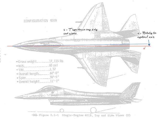
I would generally re-orient the base drawing so that the centreline of the top view and side view is horizontal so that everything is level before you start, avoids any oddities cropping up. (I suspect that you'll find some inconsistencies between the side and top views, this is normal in most drawings it seems! So you might need to tweak as you go along).
If you want to scale this to a particular scale, then you could resize the base drawing or the eventual redraw outline (I presume you're using a vector drawing software like Inkscape? - I second Arjen's recommendation to use Inkscape).
I tend to draw one half and then copy and flip for the other side, cuts the work and means its symmetrical.
Generally I do the outline first in a thicker line (something like 1px or 0.5px) and then the panel lines (0.5 or 0.25px).

I hope that this helps.
 
Hi Paul,
Dunno what software you're using. But would be easier to have good symmetric plan by rotating the top view to a straight central axis :
Unknown.jpg
 
I have Inkscape but I'm using Affinity Designer. Good call on rotating the background layer first - I was just playing around and got carried away.

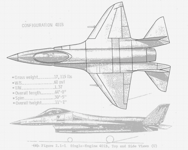
Due to the nature of the drawing, some details are only visible on one side, so I'll probably mirror both sides and combine. There's an element of guesswork interpreting such rough drawings.

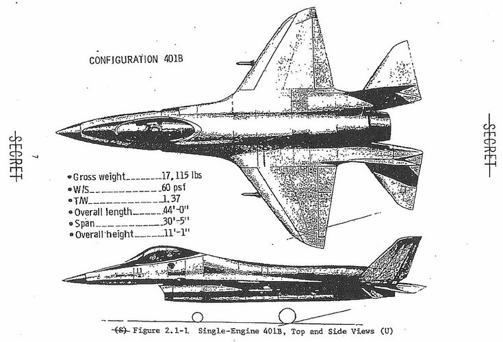
We have a good quality inboard drawing of Config 401B already, so this something of a test before I do 501A and 403 where there is no reference. The drawings differ in some small respects.

401B April 1971 [Code One] edit.png
 
Last edited:
I'm also learning with Affinity Designer.
My technique is drawing with the grid and guides activated as a reference.
Knowing the real dimensions, I convert it into convenient drawing dimensions. Just as simple.
 
How does Affinity Design compare with Illustrator?

Chris
 
I liked Illustrator, mostly used it for posters, leaflets and other printed materials for my wife's business as well as converting and tidying up Barrie Hygate's drawings for my book.

When I changed jobs I lost access to Adobe Creative Suite. The subscription price was too high, had a recommendation or Affinity Designer from @zebedee so I tried the trial version of Affinity Designer and liked it. I bought it on sale (I think Black Friday).

It does a pretty good job of loading in my existing Illustrator artwork, and I've found it pretty decent overall. The only major limitation I've found is no autotracing, for which task I use Inkscape then export as SVG to Affinity. I much prefer Affinity Designer's interface and tooling to Inkscape in general though.

For what I use it for I've found it as good or better than Illustrator.

There's no subscription, so you can use if forever, and as a private individual you can install it on as many devices as you have including different platforms like PC, Mac, iPad etc. This means my wife and daughter can have copies installed as well.

You pay an upgrade fee for major version updates but the upgrade fee is pretty reasonable. When I upgraded it to version 2, I purchased Affinity Photo and Affinity Publisher at the same time under a rather decent bundle deal.

Affinity Publisher is a pretty decent DTP package, I've been learning it instead of QuarkXpress.

Affinity Photo, my daughter uses on iPad for drawing, I still tend to use GIMP at present.
 
I've never really tried to redraw a drawing before, giving it a go because this source drawing is pretty poor. Any tips?
1: Step one is to correct the orientation of the raster image before importing into your CAD program.
2: After you import, before you do any real work, draw a series of vertical lines from top view to side... make sure that the top and side views are, in fact, lined up. And at the same scale. You'd be surprised how often *neither* are. Similarly, if you have top, side & front, make sure that all the ratios of length to span to height match up. irritatingly often, diagrams re vertically compressed by 1 to 3%. I'm guessing an issue with copying.
3: Do not do your in-progress lines in black. I use Magenta, Red and Blue, but whatever you use, make sure they jump out at you when overlaid over the background image. Easy to get lost when the raster lines are black and the vector lines are black.
4: Use heavier line weights for in-progress work, again to help them stand out.
5: "Layers" are your friends. I use layers like "Work", "Outline," "Details," etc. While in work, the line colors are garish (see #3), but when finished the line colors and weights are converted to what they are supposed to be.

When top and side and front and rear and bottom views don't match... make decisions early about what's most important. Often I take the plan view as gospel for the overall outline; the side view says where the cockpit actually goes. YMMV.

When using even the most official of official diagrams, don;t assume total accuracy. if the aircraft actually exists, get as many photos as you can, and just accept that not only will actual aircraft be built differently to what's in the diagram.... they'll be built differently to *each* *other.* So either do a diagram of a specific aircraft, or a generic mishmash.
Cheers, Scott.

This drawing is definitely distorted as I rotated it so the verticals all line up correctly, but the horizontal lines don't quite match up.
 
if the aircraft actually exists, get as many photos as you can, and just accept that not only will actual aircraft be built differently to what's in the diagram.... they'll be built differently to *each* *other.*
While this is specifically about aircraft, that bit is likewise true when applied to a class of ships.
 
Cheers, Scott.

This drawing is definitely distorted as I rotated it so the verticals all line up correctly, but the horizontal lines don't quite match up.
Having done this hundreds of times, even the most professional of hand-drafted general arrangements tended to be *loaded* with inconsistencies.

It's best by far to figure out what's goofy early. Few things more hair-pullingly irritating than getting deep into a diagram and then figuring out that it's impossible as drawn. This assumes, of course, that your goal is for *your* diagram to be internally consistent. It's fair to replicate errors, but if you do, point them out or the reader will think *you* are the idiot.
 
While this is specifically about aircraft, that bit is likewise true when applied to a class of ships.
I'd tend to think it'd probably even more true of ships. "Let's replace that 40mm AA mount with a hot dog stand."

I recently did a three-view of a Real Aircraft. Irritatingly few Official Diagrams, but shit-tons of photos. Great. But then... panel lines and even *doors* on the thing varied wildly from aircraft to aircraft.
 
It's related to production volume - the higher the numbers (and, generally speaking, the lower the amount of touch labour), the smaller the individual variations: buildings > ships > aircraft > cars > toasters > microchips.
 
Another issue: left and right (port and starboard) don't match in the plan view. Happens from time to time, sometimes badly. If you cannot determine that one or the other is correct, my approach has been to average them.
A: Mirror the raster image and overlay one layer as a transparency. Draw *between* the lines.
B: Draw the full plan view in CAD, then mirror left over right. Draw new lines between major matching points (a wingtip, say). The midpoints of these short line segments defines the average of the two views.
 
Last edited:
I liked Illustrator, mostly used it for posters, leaflets and other printed materials for my wife's business as well as converting and tidying up Barrie Hygate's drawings for my book.

When I changed jobs I lost access to Adobe Creative Suite. The subscription price was too high, had a recommendation or Affinity Designer from @zebedee so I tried the trial version of Affinity Designer and liked it. I bought it on sale (I think Black Friday).

It does a pretty good job of loading in my existing Illustrator artwork, and I've found it pretty decent overall. The only major limitation I've found is no autotracing, for which task I use Inkscape then export as SVG to Affinity. I much prefer Affinity Designer's interface and tooling to Inkscape in general though.

For what I use it for I've found it as good or better than Illustrator.

There's no subscription, so you can use if forever, and as a private individual you can install it on as many devices as you have including different platforms like PC, Mac, iPad etc. This means my wife and daughter can have copies installed as well.

You pay an upgrade fee for major version updates but the upgrade fee is pretty reasonable. When I upgraded it to version 2, I purchased Affinity Photo and Affinity Publisher at the same time under a rather decent bundle deal.

Affinity Publisher is a pretty decent DTP package, I've been learning it instead of QuarkXpress.

Affinity Photo, my daughter uses on iPad for drawing, I still tend to use GIMP at present.
Thank you for your stellar work, Sir.
 

Similar threads

Please donate to support the forum.

Back
Top Bottom