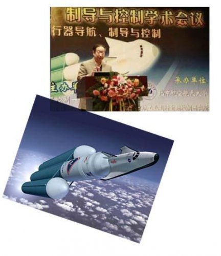
Re: otian-1, a Chinese hypersonic reentry demonstrator flown tested on 20/09/2013?
Patent No.CN103319194
Issued : 2013-09-25
Preparation method of high-strength anti-contact-damage porous SiC
Inventor(s): ZHOU YANCHUN; WANG XIAOFEI; LU XINPO; TAO MENG; HU JIDONG; SUN XIN; FENG ZHIHAI
Applicant(s): AEROSPACE RES INST OF MATERIALS AND PROC TECHNOLOGY; CN ACADEMY LAUNCH VEHICLE TECH
Application number: CN20131251379 20130624
Priority number(s): CN20131251379 20130624
Abstract : The invention relates to a preparation method of high-strength anti-contact-damage porous SiC, which comprises the following steps: (1) carbonizing wood at 600-1100 DEG C in an inert gas or hydrogen atmosphere for 1-6 hours; (2) carrying out dipping treatment on the carbonized wood in liquid polycarbosilane in a vacuum environment to obtain a carbon template; (3) curing the carbon template subjected to dipping treatment at 180-250 DEG C for 1-5 hours; and (4) carrying out high-temperature treatment on the cured carbon template in an inert gas or hydrogen atmosphere or in a vacuum environment to obtain the porous SiC ceramic. The method provided by the invention can reserve the porous structure in the wood template, so that the porous SiC can still have high compression strength under the condition of high porosity and also have excellent anti-contact-damage capacity.
Patent No. CN103253941
Issued : 2013-08-21
High-heat conductance ZrB2 high-temperature ceramics and preparation method thereof
Inventor(s): SUN XIN; ZHOU YANCHUN; LI JUNPING; FENG ZHIHAI
Applicant(s): AEROSPACE RES INST OF MATERIALS AND PROC TECHNOLOGY; CN ACADEMY LAUNCH VEHICLE TECH
Application number: CN20131172949 20130510
Priority number(s): CN20131172949 20130510
Abstract : The invention relates to a high-heat conductance ZrB2 high-temperature ceramics and a preparation method thereof, in particular relates to a method for preparing a high-heat conductance fiber toughening ZrB2 high-temperature ceramics and a method for improving the heat conductivity of a composite material, and belongs to the technical field of high-temperature ceramics. The high-temperature ceramics comprises zirconium boride powder and mesophase pitch-based carbon fiber. The ZrB2 high-temperature ceramics prepared by adopting the method has the room temperature heat conductance of 100 W/(mK) which is higher than the heat conductance of a pure ZrB2 high-temperature ceramic material (about 60W/(mK)) reported in home and abroad.
Patent No. CN102915029
Issued: 2013-02-06
Avionics system automatic test platform based on reusable spacecraft
Inventor(s): LIU XUDONG; XU HAIYUN; GAO XIANGWU
Applicant(s): CN ACADEMY LAUNCH VEHICLE TECH
Application number: CN20121388503 20121015
Priority number(s): CN20121388503 20121015
Abstract: The invention discloses an avionics system automatic test platform based on a reusable spacecraft, which comprises an interface adapter, special test equipment, a photoelectric isolation network and a test terminal. According to the characteristics that the spacecraft has many subsystems and the subsystems are distributed dispersedly, the avionics system automatic test platform based on the reusable spacecraft unifies the adapter of the comprehensive test platform, reduces the types of ground equipment, realizes functional modularization of each system and integration of the system structure, and can automatically generate and change input signals or excitation sources, automatically control the on and off of input and output of a tested object, automatically measure and record output signals, automatically process test data, automatically interpret the work state of test equipment, automatically execute test program and automatically judge the test data so as to shorten the construction time of a test system and solve the problem about distributed remote test. The test system has high generality, flexibility and test efficiency, reduces the workload of testers and improves the test quality and the test efficiency.
Patent: CN103134900
Issued : 2013-06-05
Ablation test method of thermal protection structure of high supersonic velocity aircraft
Inventor(s): CHEN DING; CHEN LIANZHONG; MA HONGQIANG; WANG YING
Applicant(s): CHINA ACADEMY OF AEROSPACE AERODYNAMICS CAAA
Application number: CN2013136622 20130130
Priority number(s): CN2013136622 20130130
Abstract: The invention discloses an ablation test method of a thermal protection structure of a high supersonic velocity aircraft. The ablation test method of the thermal protection structure of the high supersonic velocity aircraft includes the following steps: placing the thermal protection structure of the high supersonic velocity aircraft in an electric arc wind tunnel to conduct an ablation test. In the ablation test process, a computer utilizes a synchronous device to drive two cameras to conduct collection on an image pair, a filter device is adjusted in real-time to conduct light intensity adjustment to obtain an optical image quality when collection is conducted, and the computer processes the image pair which is collected at the same moment to obtain a three-dimensional morphology information of a measured object at the moment. According to three-dimensional morphology information of the measured object at different moment, ablation amount of the measured object is calculated. The ablation test method of the thermal protection structure of the high supersonic velocity aircraft is simple in operation and low in cost, can overcome extremely bad experiment conditions of the electric arc wind tunnel and can obtain surface morphology change course and ablation of the thermal protection structure of the high supersonic velocity aircraft in real-time.
Patent No. CN103090898
Date issued : 2013-05-08
Flight data recording equipment ground integrated test system
Inventor(s): QIU CHANGQUAN; ZHAO LIANG; LI XIAO; ZHANG WEI; ZHENG YU
Applicant(s): NEAR SPACE INST FOR AIRCRAFT SYSTEMS ENGINEERING; CN ACADEMY LAUNCH VEHICLE TECH
Application number: CN20111335886 20111031
Priority number(s): CN20111335886 20111031
Abstract: The invention relates to a flight data recording equipment ground integrated test system which comprises a main control computer, a simulation control computer, a verification control computer, a signal simulation sub-system, a signal simulation sub-system, a communication network sub-system and a synchronous trigger system. The main control computer completes functions of user management, report output, flight data interpretation and the like, the simulation control computer is a control main center of the signal simulation sub-system, the verification control computer is a control main center of the signal verification sub-system, the signal simulation sub-system outputs all kinds of real time simulation signals, the signal verification sub-system is composed of testing apparatus and verifies the correctness or the precision of the simulation signals output by the signal simulation sub-system, the communication network sub-system is a communication platform between computers and the testing apparatus in the system, and synchronous trigger system realizes the clock synchronization and trigger synchronization of the signal simulation sub-system and the signal simulation sub-system. The flight data recording equipment ground integrated test system provides an accurate signal source to the full test of ground environment flight data recording equipment
Patent No. CN103076806
Issued: 01/05/2013
Integrated analyzing and setting method for control parameters of three-loop automatic pilot
Inventor(s): GUO HONGBO; ZHUANG LING
Applicant(s): BEIJING AEROSPACE CHANGZHENG AIRCRAFT INST; CN ACADEMY LAUNCH VEHICLE TECH
Application number: CN20111329422 20111026
Priority number(s): CN20111329422 20111026
Abstract: The invention relates to the technical field of spacecraft control and particularly discloses an integrated analyzing and setting method for control parameters of a three-loop automatic pilot. The integrated analyzing and setting method comprises the following steps of: firstly, establishing a control loop model of the three-loop automatic pilot; secondly, setting a pitching motion relative damping coefficient after compensating an attitude angular velocity feedback circuit to acquire an attitude angular velocity control parameter and the open-loop cross-over frequency of the attitude angular velocity feedback circuit; thirdly, acquiring an open-loop gain system of a control system according to an open-loop transmission function of the control system and acquiring a closed-loop transmission function which is inputted to a guidance spacecraft by an overload instruction after correction and is outputted in an overload manner; and fourthly, acquiring the attitude angular velocity control parameter, an overload feedback control parameter and an overload instruction correction parameter. According to the integrated analyzing and setting method, the solving of a nonlinear equation is avoided; in addition, attitude stability and attitude control precision of the guidance spacecraft can be maintained by the acquired parameter under various single deviations and combined deviation and the balancing state of the spacecraft required by the guidance instruction is quickly realized.
Patent No. CN103076257
Issued: 2013-05-01
Accompanying atmospheric density measuring device
Inventor(s): ZHANG PENGYU; YANG DING; LU FENGLING; YU PING; LIU JIANHUI
Applicant(s): BEIJIN NEAR SPACE VEHICLE SYSTEM ENGINEERING RES INST; CN ACADEMY LAUNCH VEHICLE TECH
Application number: CN20111328334 20111025
Priority number(s): CN20111328334 20111025
Abstract : The invention belongs to near space environment, atmospheric density measurement, and aerodynamic parameter identification devices, and specifically relates to an accompanying atmospheric density measuring device. The device comprises a frame. Sheet metal reinforcement is applied inside the frame, such that inner devices can be fixed. A power source, a three-way overload sensor, a central processing unit, and a GPS radar integral machine are sequentially fixedly arranged on an end of the frame. An antenna is sleeved on the frame, wherein a certain gap is preserved between the antenna and the GPS radar integral machine. The invention has the advantages that: as a means for following the flight path of a reentry vehicle and for carrying our density measurement, the accompanying atmospheric density measuring system is simple and reliable, and has low cost. With the accompanying atmospheric density measuring device, measuring demands of aerodynamic parameter identification can be satisfied. Also, the invention is designed independent from a reentry vehicle, such that the overall design difficulty of the reentry vehicle is not increased.
Patent No. CN202944563
Issued: 2013-05-22
Wing body connecting layer type embedding structure of silicon substrate heat proof layer for hypersonic flight vehicle
Inventor(s): CHEN WEIHUA; ZHAO CUIMEI; CAO ZHANWEI; WANG ZHENGYU; ZHOU KEHUA; YU MINGXING; LIU QUAN
Applicant(s): BEIJING NEAR SPACE AEROCRAFT SYSTEM ENGINEERING INST; CN ACADEMY LAUNCH VEHICLE TECH
Application number: CN20122540192U 20121022
Abstract: The utility model belongs to a wing body connecting structure of a flight device, and in particular discloses a wing body connecting layer type embedding structure of a silicon substrate heat proof layer for a hypersonic flight vehicle. The structure comprises a wing heat proof layer, a wing metal structure, a metal framework and a cone heat proof layer. The wing heat proof layer is arranged outside the wing metal structure, the cone heat proof layer is arranged outside the metal framework, and the wing heat proof layer is arranged inside the cone heat proof layer. The connecting structure provided by the utility model can be used for preventing the wing front tip of the wing metal structure from warping to from a sharp stagnation point and overcoming the severe problem that the wing body connection which is not protected by the heat proof layer is directly invaded by hot air flows.
Patent No.CN102361531
Date Issued : 2012-02-22
Device and method for generating large-area, uniform and non-magnetized plasmas
Inventor(s): KAI XIE; XIAOPING LI; YANMING LIU; MIN YANG; LIANG ZHAO; YONGQIANG QIN; WEI AI; DONGLIN LIU
Applicant(s): UNIV XIDIAN; BEIJING NEAR SPACE AEROCRAFT SYSTEM ENGINEERING INST
Application number: CN20111328200 20111026
Priority number(s): CN20111328200 20111026
Also published as: CN102361531
Abstract : The invention belongs to the field of gas discharge plasmas and relates to a device for generating the plasmas through gas discharge, in particular to a device and a method for generating large-area, uniform and non-magnetized plasmas. The device is characterized by comprising a plasma generation cavity body, a vacuum device and a plasma power supply; the plasma generation cavity body comprises acylindrical cavity body and a net type discharge electrode; the net type discharge electrode is a hollow round net body, the outside diameter of which is less than the inside diameter of the cylindrical cavity body; the net type discharge electrode and the cylindrical cavity body are connected to form a concentric circle structure through an insulated support; an observing window and a hinge window are connected and fixed at two ends of the cylindrical cavity body; ; and the device can be used for researching the influence of the plasmas on electromagnetic waves. By overcoming the disadvantagesof the prior art, the device and the method for generating the large-area, uniform and non-magnetized plasmas, which are good in repetitiveness, low in error and sustainable, are provided.
Patent No. CN202946516
Issued: 2013-05-22
Screw thermal protection device
Inventor(s): CUI PIN; ZHANG HONGYU; ZHAN XUJUN; LIU GUOQIAN; CUI PENGFEI; WANG SHUYU; WANG SHAOHUA
Applicant(s): BEIJING NEAR SPACE AEROCRAFT SYSTEM ENGINEERING INST; CN ACADEMY LAUNCH VEHICLE TECH)
Application number: CN20122533222U 20121018
Priority number(s): CN20122533222U 20121018
Abstract: The utility model belongs to the technical field of thermal protection, in particular to the screw thermal protection device. The screw thermal protection device comprises a cone-shaped sleeve, a heat insulation cushion a, a heat insulation cushion b, a heat proof hat and a flexible heat insulation felt. The screw thermal protection device solves the technical problems that a screw thermal protection device in the prior art is insufficient in shear-bearing capacity and poor in high-temperature resistance, and hardly bears a high-heat-flow high-speed high-dynamic-pressure pneumatic environment of a hypersonic velocity gliding aircraft bottom sunshade device, and improves shear-bearing capacity and high-temperature performance obviously, ensures sufficient connecting strong stiffness of an ordinary screw under the act of a bottom hostile heat environment, achieves reliable connection of devices on the bottom sunshade of the aircraft bottom under the act of high heat flow, high speed and high dynamic pressure pneumatic loading.
Patent No. CN103044057
Date Issued : 2013-04-17
Carbon foam in-situ reinforced carbon aerogel high-temperature thermal insulation material and preparation method thereof
Inventor(s): LI JUNNING; HU ZIJUN; SUN CHENCHENG; WANG XIAOTING; SONG ZHAOXU
Applicant(s): AEROSPACE RES INST OF MATERIALS AND PROC TECHNOLOGY; CN ACADEMY LAUNCH VEHICLE TECH
Application number: CN2013112731 20130114
Priority number(s): CN2013112731 20130114
Abstract: The invention relates to a carbon foam in-situ reinforced carbon aerogel high-temperature thermal insulation material and a preparation method thereof; the carbon foam in-situ reinforced carbon aerogel high-temperature thermal insulation material has the characteristics of high temperature resistance, low heat conductivity and high strength, and is applicable to thermal protection system of the hypersonic speed aircraft, belonging to the technical field of high-temperature thermal insulation material. The thermal insulation material takes carbon foam which is formed in an in-situ manner as a reinforcing skeleton and carbon aerogel as a substrate, and eliminates pores between the carbon foam skeleton and the carbon aerogel caused by the conventional reinforcing method through a common carbonization; the prepared carbon foam reinforced carbon aerogel has the characteristics of high temperature resistance, low heat conductivity and high strength, and is machinable; the room temperature heat conductivity can be reduced to 0.04W/m.k, and the maximum use temperature in an inert atmosphere can reach 3000 DEG C.
Patent No. CN102709670
Issued: 2012-10-03
Magnetic antenna for improving penetrability of electromagnetic wave in plasma
Inventor(s): QING ZHAO; XIAOJUN XING; JIANMING TANG
Applicant(s): UNIV ELECTRONIC SCIENCE & TECH
Application number: CN20121212888 20120624
Priority number(s): CN20121212888 20120624
Abstract: The invention belongs to a magnetic antenna for high-speed aircraft navigation and communication, which comprises a columnar spiral antenna, a closed antenna cover, a strong magnet ground plate and a conical coaxial feeding wire column. In the magnetic antenna, the spiral antenna of an axial mode is adopted, the antenna and a strong permanent magnet are integrated, the magnet serves as a magnetic field generator to generate a high permanent field and also serves as the antenna ground plate, when magnetic field intensity B is more than or equal to 0.5T, signal emitted by the spiral antenna can effectively penetrate a plasma, when the magnetic field of the permanent magnet is increased to 1.0T, antenna gain is increased to 9.6dB and approaches 10.6dB of the antenna gain in air, and the attenuation of electromagnetic wave during transmission in the plasma is reduced by 30dB. Therefore, the magnetic antenna has the characteristics of frequency bandwidth, circular polarization bandwidth, low attenuation amplitude of the electromagnetic wave of the antenna and the like, the antenna gain and the penetrability of the plasma are effectively improved, and the defect of communication interrupt caused by the existence of a surface plasma sheath in a background technology is overcome.
Patent No. CN102447518
Issued: 2012-05-09
Signal channel comprehensive processing method used under near space hypersonic velocity condition
Inventor(s): LIANG YANG; YONGQIANG QIN; ZHENGGUANG HE
Applicant(s): NEAR SPACE INST FOR AIRCRAFT SYSTEMS ENGINEERING; CN ACADEMY LAUNCH VEHICLE TECH
Application number: CN20111356261 20111110
Priority number(s): CN20111356261 20111110
Abstract: The invention belongs to the signal channel processing method and specifically relates to a signal channel comprehensive processing method used under near space hypersonic velocity condition and aims to simulate influence of bad change of physical environment to communication. In the signal channel comprehensive processing method, when the near space aircraft is communicating with a ground base, the signal channel processing of the two parties in the communication comprises free space attenuation, atmosphere attenuation, multipath effect, Doppler shift, spatial noise and plasma sheath layer signal channel; when the near space aircraft is communicating with a space base, the signal channel processing comprises space attenuation, spatial noise, multipath effect, Doppler shift and plasma sheath layer signal channel. The invention accurately simulates signal transmission state under near space complex environment, covers physical characteristics such as black-out area, rain attenuation, low angle of elevation and etc.
Patent No.CN102724003
Date Issued: 2012-10-10
Method for testing influence of plasma on characteristics of space communication signal
Inventor(s): RUNHUI WU; MIN XI; HONGYAN LIU; GANG MENG; JIAQI LIU; ZHEFENG YU; QING CHANG; ZHIYE JIANG; YIZHOU LI; HONGJIE LI; LEI YUAN; YONG XU; YULONG LI
Applicant(s):BEIJING AEROSPACE INST OF THE LONG MARCH VEHICLE; CN ACADEMY LAUNCH VEHICLE TECH
Application number: CN20121122094 20120423
Priority number(s): CN20121122094 20120423
Abstract : The invention discloses a method for testing influence of plasma on the characteristics of a space communication signal. According to the method, the scheme of testing the influence of the plasma on the characteristics of a space transmission communication signal is designed; a comparison result of the modulated signal time domain characteristics, frequency domain (amplitude frequency and phase frequency) characteristics, demodulated and decoded eye pattern characteristics and constellation diagram characteristics of the space transmission communication signal which is transmitted in a plasma region and in a non-plasma region, and an error code counting result are given, wherein the electron density, collision efficiency and space size of the plasma region are invariables or variables; a test platform is provided for developing a ground verification test for the influence of the plasma which is in a vacuum state and has randomly-distributed characteristic parameters on the characteristics of the space transmission communication signal; and accurate measurement and data post-processing results are provided for analysis and rule summarization of the influence of the plasma in different characteristic parameter states on a ground simulation communication modulated signal transmission link.
Patent No. CN202420804
Date Issued: 2012-09-05
Modal test measuring device for hypersonic speed aircraft rudder structure at high temperature of 1400 DEG C
Inventor(s): DAFANG WU; MENG MOU; LIN ZHU; ANFENG ZHOU
Applicant(s): UNIV BEIHANG
Application number: CN2012233383U 20120202
Priority number(s): CN2012233383U 20120202
Abstract: A modal test measuring device for a hypersonic speed aircraft rudder structure at high temperature of 1400 DEG C comprises a hypersonic speed aircraft rudder structure test part, an L-shaped fixing structure, a water-cooled cooling pipeline, a silicon carbon infrared radiation array, a shock excitation source, a molybdenum force transmission rod, a molybdenum bar guide rod, an acceleration transducer, a double platinum rhodium thermocouple transducer, a computer and a high-temperature ceramic heat insulation plate. When in a hypersonic speed aircraft rudder structure test, the silicon carbon infrared radiation array heats the rudder structure, simultaneously, the shock excitation source generates random vibration, and accordingly a high-temperature thermal vibration coupling test environment is formed. The metal molybdenum bar guide rod is directly mounted on the hypersonic speed aircraft rudder structure, vibration signals of the hypersonic speed aircraft rudder structure are transmitted out of a high-temperature thermal field at the temperature of 1400 DEG C, the normal-temperature acceleration transducer mounted at a cold end of the molybdenum bar guide rod is used for dynamically measuring thermal modal signals of the rudder structure, the thermal modal signals of the rudder structure are guided to a normal temperature region, and an effective dynamic high-temperature thermal modal test means is provided for developing a hypersonic speed long-range strategic aircraft.
Patent No. CN102509946
Date Issued: 2012-06-20
Single-ended control and double-ended separation separable electric connector
Inventor(s): MINGJIAN PAN; BIN LI; JUNPENG CUI; JINGHUI LAN; LIXIA RONG; JUANJUAN CAO
Applicant(s): BEIJING NEAR SPACE AEROCRAFT SYSTEM ENGINEERING INST; CN ACADEMY LAUNCH VEHICLE TECH
Application number: CN20111335888 20111031
Priority number(s): CN20111335888 20111031
Also published as: CN102509946
Abstract : The invention belongs to the technical field of electric connectors, relates to separation-break-away electric connectors, and particularly relates to a singe-ended control and double-ended separation separable electric connector. At present, the singe-ended control and double-ended separation separable electric connector solves the problem of electrical connection of complete disconnection of a connector under long-time high-temperature conditions. The separable electric connector comprises an outer plug, a socket and an inner plug, a double-ended locking device is arranged in the socket, and the outer plug and the inner plug respectively comprise a set of electromagnetic separation mechanism.; An RC delay circuit and an outer electromagnetic coil are arranged in the outer plug, an inner electromagnetic coil is arranged in the inner plug, and both the inner electromagnetic coil and the outer electromagnetic coil are controlled by a control end outside the outer plug. The separable electric connector is simple, high in reliability and capable of adapting to long-time high-temperature thermal protection.
Patent No. CN202305096
Date Issued: 2012-07-04
High-sensitivity optical fiber micro-range atmospheric pressure sensor
Inventor(s): XIAOLI QIN; SHENG LIANG; PENGYU ZHANG; DING YANG; MING LIU; JIANHUI LIU
Applicant(s): NEAR SPACE INST FOR AIRCRAFT SYSTEMS ENGINEERING; CN ACADEMY LAUNCH VEHICLE TECH
Application number: CN20112417471U 20111027
Priority number(s): CN20112417471U 20111027
Abstract: The utility model belongs to the field of a sensor, and particularly relates to a high-sensitivity optical fiber micro-range atmospheric pressure sensor. The utility model provides a high-sensitivity optical fiber atmospheric pressure sensor which is used for micro-range atmospheric pressure measurement and applied to the application requirements, such as space flight and aviation aircraft parameter identification and the like. The high-sensitivity optical fiber micro-range atmospheric pressure sensor specifically comprises an optical fiber circulator, a sensing unit, a photoelectric detector and optical fibers for connecting all components, wherein an optical fiber Bragg grating in the sensing unit is adhered to the surface of a vacuum box in a curve mode; external atmospheric pressure to be measured acts on the vacuum box, the vacuum box deforms under the action of the external atmospheric pressure to cause the optical fiber Bragg grating adhered to the surface to be subjected to homogeneous deformation so that the chirp rate of the optical fiber Bragg grating is modulated; and the variation of the chirp rate of the optical fiber Bragg grating causes the spectral width of a reflection spectrum to be changed, so that the luminous power is changed, and the variation of luminous power is extremely sensitive, so as to finally meet the requirements of the sensor on high sensitivity and micro-range atmospheric pressure measurement.
Patent No. CN102539099
Date Issued: 2012-07-04
Measuring device for 1400 DEG C high-temperature modal test of wing helm structure of hypersonic aircraft
Inventor(s): DAFANG WU; BING PAN; YUEWU WANG; BING SUN; LIMING ZHENG
Applicant(s): UNIV BEIHANG
Application number: CN2012123576 20120202
Priority number(s): CN2012123576 20120202
Abstract: The invention relates to a measuring device for a 1400 DEG C high-temperature modal test of a wing helm structure of a hypersonic aircraft. The measuring device comprises a test piece of the wing helm structure of the hypersonic aircraft, an L-shaped fixed bracket, a water-cooling pipeline, a silicon carbon infrared radiation array, an excitation source, a molybdenum force transfer rod, a molybdenum-rod guide bar, an acceleration sensor, a dual platinum rhodium thermocouple sensor, a computer and a high-temperature ceramic heat-insulating plate. When the test for the wing helm structure of the hypersonic aircraft is performed, the wing helm structure is heated by the silicon carbon infrared radiation array, and meanwhile, the excitation source is randomly vibrated, thereby forming an environment of a high-temperature thermal vibrating coupling test. The metal molybdenum-rod guide bar is directly mounted on the wing helm structure of the hypersonic aircraft; a vibrating signal of the wing helm structure of the hypersonic aircraft is transferred to a place beyond a 1400 DEG C high-temperature thermal field; a normal-temperature acceleration sensor is mounted at a cold end of the molybdenum-rod guide bar, so as to dynamically measure a thermal modal signal of the wing helm structure introduced into a normal temperature area; and the invention provides an effective dynamical high-temperature thermal modal test means for developing a hypersonic remote strategic aircraft.
Patent No. CN102724003
Date issued: 2012-10-10
Method for testing influence of plasma on characteristics of space communication signal
Inventor(s): RUNHUI WU; MIN XI; HONGYAN LIU; GANG MENG; JIAQI LIU; ZHEFENG YU; QING CHANG; ZHIYE JIANG; YIZHOU LI; HONGJIE LI; LEI YUAN; YONG XU; YULONG L
Applicant(s): BEIJING AEROSPACE INST OF THE LONG MARCH VEHICLE; CN ACADEMY LAUNCH VEHICLE TECH
Application number: CN20121122094 20120423
Priority number(s): CN20121122094 20120423
Abstract : The invention discloses a method for testing influence of plasma on the characteristics of a space communication signal. According to the method, the scheme of testing the influence of the plasma on the characteristics of a space transmission communication signal is designed; a comparison result of the modulated signal time domain characteristics, frequency domain (amplitude frequency and phase frequency) characteristics, demodulated and decoded eye pattern characteristics and constellation diagram characteristics of the space transmission communication signal which is transmitted in a plasma region and in a non-plasma region, and an error code counting result are given, wherein the electron density, collision efficiency and space size of the plasma region are invariables or variables; a test platform is provided for developing a ground verification test for the influence of the plasma which is in a vacuum state and has randomly-distributed characteristic parameters on the characteristics of the space transmission communication signal; and accurate measurement and data post-processing results are provided for analysis and rule summarization of the influence of the plasma in different characteristic parameter states on a ground simulation communication modulated signal transmission link.
Patent No. CN102447518
Date Issued:
Signal channel comprehensive processing method used under near space hypersonic velocity condition
Inventor(s): LIANG YANG; YONGQIANG QIN; ZHENGGUANG HE
Applicant(s): NEAR SPACE INST FOR AIRCRAFT SYSTEMS ENGINEERING; CN ACADEMY LAUNCH VEHICLE TECH
Application number: CN20111356261 20111110
Priority number(s): CN20111356261 20111110
Abstract: The invention belongs to the signal channel processing method and specifically relates to a signal channel comprehensive processing method used under near space hypersonic velocity condition and aims to simulate influence of bad change of physical environment to communication. In the signal channel comprehensive processing method, when the near space aircraft is communicating with a ground base, the signal channel processing of the two parties in the communication comprises free space attenuation, atmosphere attenuation, multipath effect, Doppler shift, spatial noise and plasma sheath layer signal channel; when the near space aircraft is communicating with a space base, the signal channel processing comprises space attenuation, spatial noise, multipath effect, Doppler shift and plasma sheath layer signal channel. The invention accurately simulates signal transmission state under near space complex environment, covers physical characteristics such as black-out area, rain attenuation, low angle of elevation and etc.
Patent No. CN102479269
Date Issued: 2012-05-30
Method for converting fluid load into solid load
Inventor(s): XIAOFENG WANG; JUNPENG HUI; JIANBIN WANG; TINGTING MA; QING GAO; DELI LIANG; HAO ZHANG; DAIMEI CHEN
Applicant(s): BEIJING NEAR SPACE AEROCRAFT SYSTEM ENGINEERING INST
Application number: CN20101565341 20101129
Priority number(s): CN20101565341 20101129
Also published as: CN102479269
Abstract : The invention relates to a method for converting a fluid load into a solid load. The method sequentially comprises the following steps of: 1, establishing a fluid field computing model; 2, establishing a solid computing model; 3, collecting the area of a stress surface; 4, establishing local coordinate systems; 5, establishing a transformation matrix among the coordinate systems; 6, obtaining solid structure units corresponding to pneumatic grid nodes; 7, obtaining a concentrated force; 8, establishing isoparametric units; 9, establishing a mapping relationship between the solid structure units and the corresponding isoparametric units; 10, establishing an area infinitesimal; 11, obtaining all node forces in the local coordinate systems according to a principle of minimum potential energy; 12, converting the node forces into an integral coordinate system; ; and 13, obtaining the node force of each solid structure unit. In the invention, according to the principle of minimum potential energy, the conversion from the fluid load to the solid load can be realized well, so that higher precision can be achieved and the method has a higher actual application value.
Patent No. CN101885380
Date issued: 2010-11-17
Asymmetrical design method for leading edge of hypersonic vehicle
Inventor(s): LURONG XIE; WEIXING WANG; RONGWEI GUO
Applicant(s): UNIV NANJING AERONAUTICS
Application number: CN20101225463 20100713
Priority number(s): CN20101225463 20100713
Abstract : The invention relates to an asymmetrical design method for the leading edge of a hypersonic vehicle, belonging to the technical field of hypersonic vehicles. The method is characterized by comprising design steps of a lip cover leading edge (1) and a compression surface leading edge (2). The design steps of the lip cover leading edge are as follows: making an auxiliary line perpendicular to a first form line and a fourth form line which are parallel to each other; chamfering the auxiliary line ant the first form line with RL=d to obtain an auxiliary arc; and chamfering the auxiliary arc and the fourth form line with rC to obtain a second form line and a third form line. The design steps of the compression surface leading edge are as follows: chamfering the compression surface leading edgeto determine a leading edge point; making an auxiliary line perpendicular to the angular bisector of the first form line and the fourth form line through the leading edge point; chamfering the first form line and the auxiliary line with rC to obtain a second form line; and chamfering the fourth form line and the auxiliary line with RC to obtain a third form line tangent to the second form line. Compared with a symmetrical configuration, rL/RL is greater than 0.06 and less than 0.2, and the peak value of heat flow of the lip cover leading edge is furthest decreased by 27.4 percent; and rC/RC is greater than 0 and less than 1, the total pressure recovery of a gas inlet channel is furthest increased by 11.6 percent, and the capture flow is furthest increased by 6.29 percent.
Patent No. CN201877521
Date Issued: 2011-06-22
Automatic activation type lithium-sulphur battery pack
Inventor(s): LIXIA RONG; BIN LI; JUNPENG CUI; JINGHUI LAN; JUANJUAN CAO; HONGXIN JIN; MINGJIAN PAN
Applicant(s): BEIJING NEAR SPACE AIRCRAFT SYSTEM ENGINEERING RES INST
Application number: CN20102633824U 20101129
Priority number(s): CN20102633824U 20101129
Abstract: The utility model relates to an automatic activation type lithium-sulphur battery pack, comprising a shell, an electric connector positioned on the shell and a plurality of single lithium-sulphur battery bodies fixed at the lower part in the shell, and further comprising a liquid storage device fixed at the upper part in the shell, and a gas generator positioned in the shell and connected with the electric connector, wherein a gas outlet of the gas generator is connected with the liquid storage device in a sealing manner; the liquid storage device is internally provided with an inner bag containing electrolyte; the lower part of the inner bag is provided with a liquid outlet on which a sealing film is arranged in a sealing manner; the liquid outlet of the inner bag is connected with a liquid filling hole at the lower part of the liquid storage device in a sealing manner; the position at the lower part of the liquid storage device, which corresponds to the liquid filling hole, is provided with an electrolyte distributing groove; the electrolyte distributing groove is provided with liquid filling pipelines which are respectively connected into all the single lithium-sulphur battery bodies in the sealing manner; an exhaust hole is arranged at the upper part of each single lithium-sulphur battery body; and each single lithium-sulphur battery body is connected with the electric connector. In the automatic activation type lithium-sulphur battery pack, the influence of self charging on the storage period of batteries is overcome, so that the storage period can be prolonged to 5-8 years.
Patent No.CN102097622
Date Issued: 2011-06-15
Sulfur-containing composite anode material, anode plate and Li-S (lithium-sulfur) secondary battery and preparation method thereof
Inventor(s): KAI XIE; XIAOBIN HONG; SHIZHAO XIONG; LIXIA RONG; JUNPENG CUI
Applicant(s): NAT UNIV DEFENSE TECHNOLOGY; BEIJING INST OF NEAR SPACE VEHICLE S SYSTEM ENGINEERING
Application number: CN2011120323 20110118
Priority number(s): CN2011120323 20110118
Abstract : The invention discloses a sulfur-containing composite anode material which is of a core-shell structure, wherein a core is a C/S (carbon/sulfur) composite composited by utilizing elemental sulfur and nano conductive carbon black; and a shell is an organic polymer clad film layer containing a plasticizer. The preparation method comprises the following steps: mixing the sulfur and carbon and heating to obtain the C/S composite; adding an organic polymer solution; emulsifying and shearing the mixture; and finally filtering and drying. The invention further discloses an anode plate which comprises an aluminum current collector and the sulfur-containing composite anode material coated on the aluminum current collector.; The anode plate is prepared by ball milling and blending the sulfur-containing composite anode material with adhesives, a solvent and process additives, and printing or coating on the aluminum current collector. The invention also discloses a Li-S (lithium-sulfur) secondary battery which is formed by packaging a battery core and an electrolyte, wherein the battery core mainly comprises a cathode component, a polymer porous diaphragm and the anode plate. The cathode component comprises a lithium foil, and the electrolyte comprises an organic solvent and lithium electrolyte salts. The secondary battery disclosed by the invention has the advantages of high specific energy and good cycle performance.


