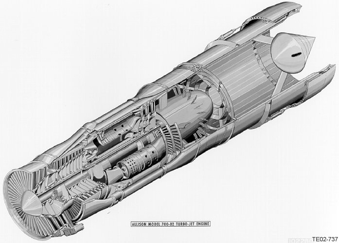
Allison Model 700-B2 (XJ89-A-1)

D

Deleted member 2278

Guest
Could anyone please help me identify some of the engines being compared in the paper linked below?


On Page 8, a Wright TJ37 (Orpheus) & GE 279 (J93 I believe) are being compared with an Allison 640 (according to Mr Chong, the XJ89) and some mystery items. The Wright WTF10/12 & Allison 700-PD5 turbofans and the Allison 670 turbojet are new to me. A cursory search didn't throw up anything obvious. Does anyone have a Scooby?

ETA: Edited thread title to better reflect contents.
 
Upon further reading, the Allison 640 and J89 would appear to be separate entities.

Aviation Week & Space Technology 1957-10-07 Page 72, under the section "Use of Plant 8" has the Allison 640 as a single-spool loser for propelling the WS-110A.


Aviation Week & Space Technology 1957-09-16 Page 23, under Industry Observer, has the J89 as a 12-to-1 pressure ratio twin-spool engine that bypasses flow around the high-pressure compressor above Mach 2.


An image of the J89's turbine casing can be found of Page 71 of the first link.
 
I remember reading in American Secret Projects: Fighters and Interceptors 1945-1978 by Tony Buttler that the Northrop N-167 interceptor was originally to be powered by two Allison J89 turbojets before they switched over to using four J79 turbojets for the interceptor. Any info regarding the J89 engine?
 
The Allison XJ89 Turbojet

As the Cold War developed in the years after World War II, consensus among the U.S. Armed Forces emerged that the United States required a strategic bomber with intercontinental high-speed capability. In November 1955, Boeing and North American were awarded Air Force contracts to initiate preliminary design of what would become the Mach 3 XB-70 Valkyrie. Approximately six months later, Allison and General Electric were asked to submit engine proposals in support of the project.

Allison’s response to the Air Force request was the Model 700-B2, which received the military designation XJ89-A-1. Although it was designated a turbojet, it was actually a low bypass turbofan.

The engine was Allison’s first twin-spool design, which featured a three-stage low pressure (LP) compressor, an eight-stage high pressure (HP) compressor, a single-stage LP turbine, a two-stage HP turbine, a high-altitude afterburner, and a variable-area plug-nozzle exhaust system. Air was carried from the outlet of the LP compressor around the HP compressor and reintroduced upstream of the afterburner. The controls and accessories were housed inside a cooled compartment to protect them from the temperatures resulting from high-Mach flight.

Maximum thrust was 34,500 lb at sea level. The engine was designed for Mach 2.8 at altitude with a Mach 3.0 objective. Maximum guaranteed altitude was 75,000 ft. The XJ89 was built and tested. Several variations were evaluated, including some with other design Mach numbers and others without an afterburner.

North American initially felt that the Allison XJ89 was “far better [than the GE offering] at high altitude and high Mach,”1 but GE improved its design in an attempt to narrow the gap. By April 1957, North American and Boeing announced that the two competing engines were virtually identical in projected performance and availability. On May 1, 1957, the Air Force declared GE the winner of the engine competition, thus terminating the XJ89 program.

AIAA 2002-3566
The Forgotten Allison Engines
D. T. Jensen and J. M. Leonard
Rolls-Royce Heritage Trust, Allison Branch
Indianapolis, IN
 

Attachments

  • XJ89.jpg
    XJ89.jpg
    301.5 KB · Views: 99
Two observations from the cross section:
- the combustor was a cannular design. Typical of that era
- the plug for the nozzle was suspended in the exhaust flow. Never have seen that before. Usually there is a cooled structure running aft from the turbine exhaust case to the plug. Variable convergent nozzle around the plug section. I could see that cooling air would have to be conducted thru the plug supports inward to the plug to allow it to live during AB operations. Would it have worked ?
 
To think we almost had a turbofan in service with this engine...
 
Last edited by a moderator:
Two observations from the cross section:
- the combustor was a cannular design. Typical of that era
- the plug for the nozzle was suspended in the exhaust flow. Never have seen that before. Usually there is a cooled structure running aft from the turbine exhaust case to the plug. Variable convergent nozzle around the plug section. I could see that cooling air would have to be conducted thru the plug supports inward to the plug to allow it to live during AB operations. Would it have worked ?

Remarkable how enormous the combustor section is compared to the compressors, too. Again a feature to some extent typical of the era, but it still seems particularly bulky (though the drawing may distorting scale somewhat).

Regarding the plug nozzle, since the engine architecture is very similar to a modern low-bypass turbofan, cooling could be effected in a similar manner to the radial reheat flameholders in the F414, EJ200, M88 etc. That is to say, ducting cool (bypass) air inward from behind the screech liner though the support struts, as you say. Seems a rather convoluted way to implement a variable plug nozzle compared to a translating centrebody, I concur.
 
Perhaps of interest as an example of a translating centerbody (although not with an afterburner) was the re-engined TU-144. The RD-36 non-afterburning turbojet centerbody was perforated and compressed air forced through the holes for noise attenuation around airports. ref Tupolev Tu-144 by Gordon,Komissarov and Rigmant, p.188.

Remarkable how enormous the combustor section is compared to the compressors, too. Again a feature to some extent typical of the era, but it still seems particularly bulky (though the drawing may distorting scale somewhat).

Regarding the plug nozzle, since the engine architecture is very similar to a modern low-bypass turbofan, cooling could be effected in a similar manner to the radial reheat flameholders in the F414, EJ200, M88 etc. That is to say, ducting cool (bypass) air inward from behind the screech liner though the support struts, as you say. Seems a rather convoluted way to implement a variable plug nozzle compared to a translating centrebody, I concur.

Burning actually happens downstream of flameholders so using bypass air is only good enough for dealing with radiation from the flame.
To explain this we have the contemporary J58 (Blackbird) afterburner description "Flameholders are placed close to spraybars so fuel does not have time to vaporize and ignite ahead of the flameholder and burn it'. ref https://authors.library.caltech.edu/records/6s4e6-b2j60 , AE107_SR-71_Case_Study_321-450.pdf pp. 72,73 The flameholders are in exhaust gas temperature 1450F, the afterburner flame is 3200F.

Incidentally, for excellent pictures of spraybars and flameholders see https://en.wikipedia.org/wiki/Jet_e..._Rolls-Royce_Turboméca_Adour_turbofan_(2).jpg
 
Two observations from the cross section:
- the combustor was a cannular design. Typical of that era
- the plug for the nozzle was suspended in the exhaust flow. Never have seen that before. Usually there is a cooled structure running aft from the turbine exhaust case to the plug. Variable convergent nozzle around the plug section. I could see that cooling air would have to be conducted thru the plug supports inward to the plug to allow it to live during AB operations. Would it have worked ?
We might say a plug obviously? can't stand afterburner temperatures so why even bother to think about it? The attraction is a translating plug is more efficient than a con-di nozzle. For this reason it was evaluated for the Concorde powerplant but rejected on too heavy and cooling unknowns although Concorde only had partial reheat, ie lower temperatures than full. ref "A Case Study By Aerospatiale And British Aerospace On The Concorde" Rech and Leyman, p.6-10.
 
As I noted in my original comment, most plug nozzles have been mounted on a sting support aft of the inner wall of the turbine exhaust case. Variable convergent area is accomplished by axial translation of the plug.

On the XJ89 cross section, it is showing the plug supported by three struts coming from the AB OD duct. The struts and the forward face of the plug would have been exposed to the AB flame and would need massive cooling. The convergent area appears to to be controlled by movable flaps around the OD of the AB.

Plug nozzle have a lot of performance advantages over traditional Convergent/Divergent nozzles. They have been used successfully in supersonic non-AB engines such as the Tu-144/D36 and the Hounddog missile / J52. I don’t know if they achieved long term durability in either of these applications, with that version of the Tu-144 not being introduced to fleet service, and the Houndog used to assist B-52 takeoffs (multiple uses, but short duration) and then a one way trip to the target. I am unaware of any successful afterburning turbojet / turbofan engines with a plug nozzle. Rockets may be another more successful application with the short distance from the combustion chamber to nozzle throat and the use of regenerative cooling of the plug.
 
The engine was RD-36-51A not RD-36.

This distinction is important because the 36 in this designation refers to OKB-36 (P. A. Kolesov) - all engines from this OKB in a certain time period are RD-36- something. The RD-36-41 and RD-36-51 are different (somewhat related) engines, not two variants of the same engine, and RD-36-35FV is an unrelated liftjet.


Other Soviet engines had the OKB number in there.

Isotov TV3-117 - 117 is the OKB number
Tumansky R13-300 - 300 is trhe OKB number
 
Thanks for the clarification. I’m
not that familiar with the Soviet / Russian engine designation system.
 

Similar threads

Please donate to support the forum.

Back
Top Bottom