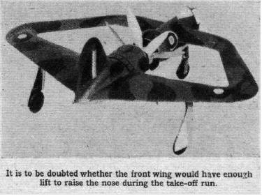
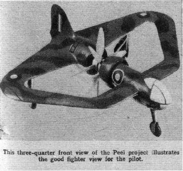
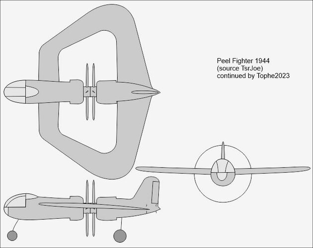
A fighter designed by Leslie Peel (1944)

If you read the article you'll discover that it is not a "Bristol" design but one designed by a Private in the Army - Leslie Peel.

The only mention of Bristol is in relation to the sleeve valve engine that they persevered at and perfected.

Regards,
Barry
 
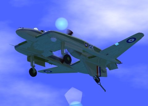
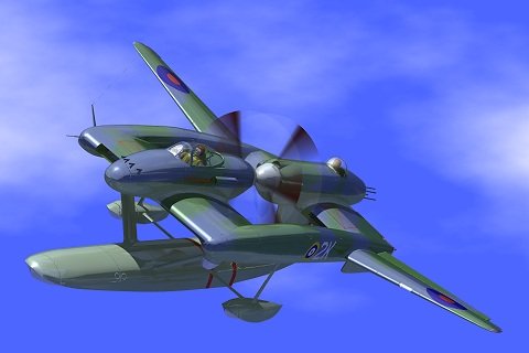
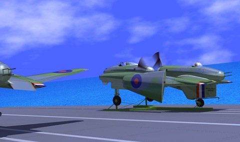
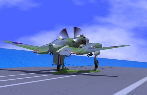
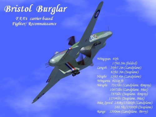
Its surprisingly similar to this fictional design which is from a Japanese website that holds competitions for fictional aircraft, ships and vehicles. The artwork is usually great.
 

Attachments

  • burglar_4.jpg
    burglar_4.jpg
    32 KB · Views: 470
  • burglar_3.jpg
    burglar_3.jpg
    31.4 KB · Views: 508
  • burglar_2.jpg
    burglar_2.jpg
    30.6 KB · Views: 737
  • burglar_1.jpg
    burglar_1.jpg
    31.7 KB · Views: 769
  • burglar_0.jpg
    burglar_0.jpg
    57.5 KB · Views: 881
Yes indeed , or an early attempt of joined wing thinking..
 
With its twin-booms, it looks more plausible, than this Bristol
design, I think. But with hindsight it may be easier to create
a WW II design .... ;D
 
But what kind of advantages could have this special design??
The configuration is one of the oddest I've ever seen.

Anyway thanks to Hesham for this special finding...
 
The advantage would be the use of contrapropos without the use of a gear and
positioning the props in the in the middle, so without disturbing the airflow
around the nose. Was tried in some other designs, too, such as the BV P.192.
But if it is really worthwhile, I don't know .... ???
 
The idea of two engines mounted front to front
was also used by Roberto Bartini in the intial design
for his DAR flying boat in the late 1930's.
 
Beautiful design, I suspect though that it would be possible only with much later structural engineering and materials... ???I tremble thinkg of the aeroelastic forces the aircraft would have been subjected ito n a gust: very much probably tearing it apart :(
 
I rather think that bailing out would be a very interesting adventure in that aircraft. It would also have some very interesting stall characteristics, with effectively what would be a "blown" wing in the rear. Could make landing quite an interesting adventure as well, particularly with the location of the tail-hook.
 
The first picture from flightgolabal is reminiscent of the Geobat which is a great circular wing design. Excellent.
 
Jemiba said:
As this thread came up again, I modified the title to give credit to the true designer. ;)

Cool. But why lose the mention "Bristol" in the title if this truly was a Bristol project? :(
 
Stargazer2006 said:
Cool. But why lose the mention "Bristol" in the title if this truly was a Bristol project? :(

Because I cannot find a clue in the Flight article, that it really was. To my opinion, Bristol is
only mentioned with regards to the sleeve valve. All aircraft designs are just mentioned with
regards to their designers, for the one we are speaking about " Definitely in the class of annular
plan forms falls a project sent to us by a private in the army, Mr. Leslie Peel, whose design is shown in
model form ....."
But maybe I'm wrong, then I'll add Bristol to the title again, of course. ;)
 
Beautiful design, I suspect though that it would be possible only with much later structural engineering and materials... ???I tremble thinkg of the aeroelastic forces the aircraft would have been subjected ito n a gust: very much probably tearing it apart :(
The wings would be stiffer if they joined just outboard of the prop tips. ... perhaps more like the twin-booms on the speculative Japanese sketches. Those (speculative) booms need to be stiff enough to prevent forward and aft wings from flexing up and down relative to each other.
IOW a shorter load path will be stiffer.
Reducing aero-elasticity would also reduce the prospects of prop blades clashing.
We wonder if it is practical to join the two prop hubs with a ball-bearing ... to reduce relative motion.??????
 
But what kind of advantages could have this special design??
The configuration is one of the oddest I've ever seen.

Anyway thanks to Hesham for this special finding...
There are multiple advantages.

First, the pilot has great visibility.

Second, it can concentrate all guns in the nose ... simplifying alignment and aiming. Mounting heavy guns near the center-line increases roll rates.

Thirdly, it will balance better than most flying wings, tandem-wings and canards because heavy engines are near the center-of-gravity. That also allows for quicker pitch changes (versus Dornier 335 with props at the extreme ends of a long fuselage).

Fourthly, it balances engine weight without long drive shafts (Curtiss Ascender, Japanese Shiden, etc.).

Fifth, the rear prop is forward of the main wheels, eliminating the risk of prop strikes (on the runway) or the need for a tail bumper.

Sixth, the rudder is far enough aft (of the C. of G.) to provide meaningful stability and control.

Seventh, the rudder is a convenient place to hang an arrestor hook for carrier landings.

Eighth, the configuration is more of a tandem-wing or canard, specifically because the forward wing is smaller (narrower chord) than the rear wing. Both can provide lift. ... allowing the forward to wing to provide lift at high angles of attack. This would help with the STOL landings needed for deck landings. Consider that SAAB's Viggen and Grippen canards are among the few STOL jet fighters.

If you worry about the pilot bailing out past those spinning props, just bolt his seat to a lever arm (as suggested for Spitfire). The lever arm only has to be long enough to lift him above/below the prop arc.

In conclusion, whether this airplane could be successful is a question of balancing extra structural weight versus all the advantages mentioned above.
 
Last edited:
There is an e-VTOL proposal that uses an almost identical wing form to that. Must be some perceived advantage to the design to have cropped up more than once and so far apart.
 
Its surprisingly similar to this fictional design which is from a Japanese website that holds competitions for fictional aircraft, ships and vehicles. The artwork is usually greBristol Burglar would be

Its surprisingly similar to this fictional design which is from a Japanese website that holds competitions for fictional aircraft, ships and vehicles. The artwork is usually great.
This fictional Bristol Burglar makes more sense structurally. By mounting booms just outboard of prop discs, it reduces the length, weight and flexibility of the whole structure. This stiffer structure also reduces the risk of props flexing out of alignment. We wonder if it is practical to directly connect the prop hubs to reduce relative vibrations. If the suggested bearing only limits the relative movement of the two props, it will further stiffen the entire airframe both vertical and horizontally. We also hope that shorter structural load paths will reduce vibrations.
 
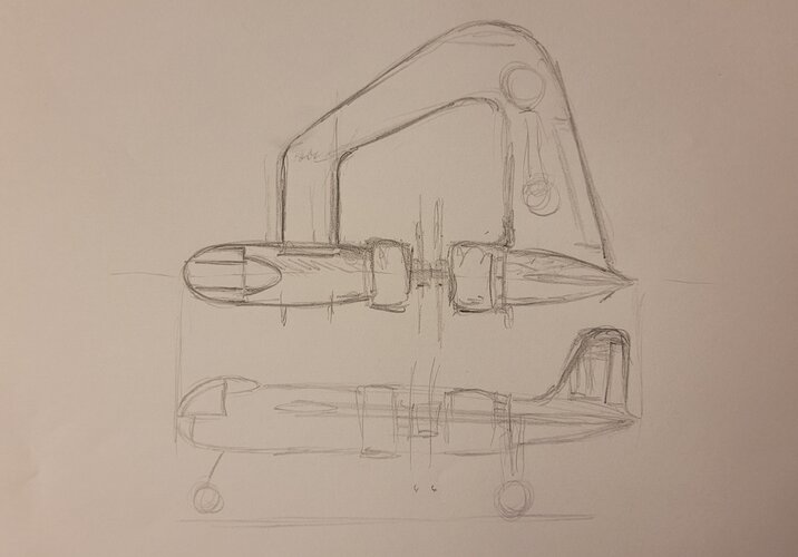
Has anyone tried sketching out a ga. drawing of the Peel design ? Im thinking the engine cowling might provide for a base dimension ? would certainly make for an interesting model :)

I have appended a very rough doodle to try visualise the shapes
 

Attachments

  • 20230124_171516.jpg
    20230124_171516.jpg
    1.5 MB · Views: 61
Last edited:
The idea of two engines mounted front to front
was also used by Roberto Bartini in the initial design
for his DAR flying boat in the late 1930's.
Are you sure?
Do you have a photo or drawing of that Bartini DAR variant?

The only photo that I was able to find of a Bartini DAR flying boat has the same configuration as Dornier Whal with a pair of engines mounted push-me-pull-you about the center of its parasol wing. That version of Bartini DAR had a tractor propeller mounted ahead of the parasol wings' leading edge and a pusher prop mounted immediately behind the trailing edges.

Savio-Marchetti's S.65 Schneider Cup racer also had a pair of engines mounted push-me-pull-you style in a small nacelle that also included the cockpit. Tail feathers were mounted to the aft end of twin pontoons. This leaves us wondering why more float planes do not mount their tail feathers to the ends of their pontoons. Perhaps that configuration is limited to bespoke racers.
Yesssss, I know that the bulk of working bush-planes (Beechcraft, Cessna, Fairchild, Fokker, Noordyn Norseman, Piper, Porter, Quest Kodiak, Stinston, Waco, etc.) are just bolt-on modifications of conventional land-planes.

I also vaguely remember another Schneider Cup racer with a pusher prop mounted immediately behind the trailing edges and the tail feathers mounted at the aft end of a single, center-line float. I doubt if that project got beyond the drafting board. The single center-line float was stiff enough to prevent tail feathers flying in too loose a formation. (A joke about aerodynamic flutter.)
A (fictional) variation on this theme would mount the rear engine above the aft portion of the central float/pontoon.

Overall, the biggest engineering challenge to mid-fuselage mounted propellers is building an aft fuselage stiff enough to mount tail feathers.
 
That 'Peel' is a truly disconcerting design.
Agreed, putting a flexible bearing between the prop-shafts may usefully augment the 'fuselage' stiffness.

Like the US 'flying pancakes' that never made it beyond prototype, this layout looks to have good STOL properties. And, unlike those hapless 'flap-jacks', short drive-shafts...

How slow could it fly ??

I reckon needs a much bigger rudder, as losing one engine or simply running one 'feathered' for economy could really, really struggle.

Plenty of wingspan to hang 'stores', fit cannon etc...
Even so, chord looks a tad lean...

The only 'killer' would seem the length of control runs, though presumably duplicated L/R to mitigate damage issues...

Unless, like spinner cannon, control lines run through the prop-shafts ??? :eek::eek: ( No, no, no, do not go there... )
 
Has anyone tried sketching out a ga. drawing of the Peel design ? Im thinking the engine cowling might provide for a base dimension ? would certainly make for an interesting model :)
If Peel's proposed fighter was powered by pre-war Bristol Perseus engines with a diameter of 55.3 inches/1.405mm. Add a few inches for the cowling and you get an outside diameter of around 60 inches/1.5 meters.
Mid-war Bristol Hercules and post-war Centarus have essentially the same diameter.

The next question is propeller diameter.
Perseus (830 horsepower) typically turned 3-bladed propellers when installed on Lysanders and Blenheims.
When installed on Bristol Freighters, Hercules (1615 hp.) turned 14 foot/4.3 meter diameter propellers.
Post-war Centaraus (2,520 hp.) turned 5-bladed propellers when installed on Hawker Sea Fury.
 
Another way to stabilize the two propellers - relative to each other - would be to start with the fictional Japanese burglar_3.jpg float-fighter then add an A-frame of struts coming up from the center float to hold a bearing between the two propeller spinners.
 
Sorry, I forgot to update the order of objects, for the main landing gear on the profile.
Corrected below:
Thanks for your sketches.
The next step is figuring out a cooling scheme for the rear engine. Those stock Townsend/NACA cowlings will merely dump warm air from the front engine into the rear engine. May I suggest squeezing the outlet for the front engine so that it becomes an iris with a vertical axis (think cats-eye).
Then shift inlets for the rear engine so that they resemble the inlets for a horizontally-opposed engine (think Continental, Franklin, Lycoming and Rotax). That scheme failed on an early Curtiss P-40, so will need further refinement?????????
 
This engine configuration was test-flown back in 1941 on an American prototype built by A.C. Johnson and flew about 200 hours before it was grounded by the war in 1941. Post-war, Johnson planned to test fly it some more and refine it for production.
Photos and a brief description appear on the Secret Early Aircraft Projects forum posts number 46 band 47. It was powered by a pair of 80 horsepower, Franklin, horizontally-opposed, air-cooled engines. 80 hp. sounds like enough to fly a light two-seater, but I wonder if it could still climb after one engine quit.
The key difference between Peel's and Johnson's configurations is that Johnson used a center keel to hold the two propellers in alignment. In that respect, Johnson's fuselage resembled a low-winged Luton Buzzard with both propellers rotating above a rigid wing center section.
 

Similar threads

Please donate to support the forum.

Back
Top Bottom