Wurger

ACCESS: Top Secret
Senior Member
Joined
25 October 2007
Messages
1,088
Reaction score
338
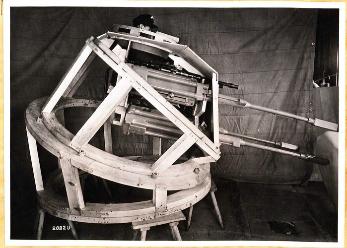
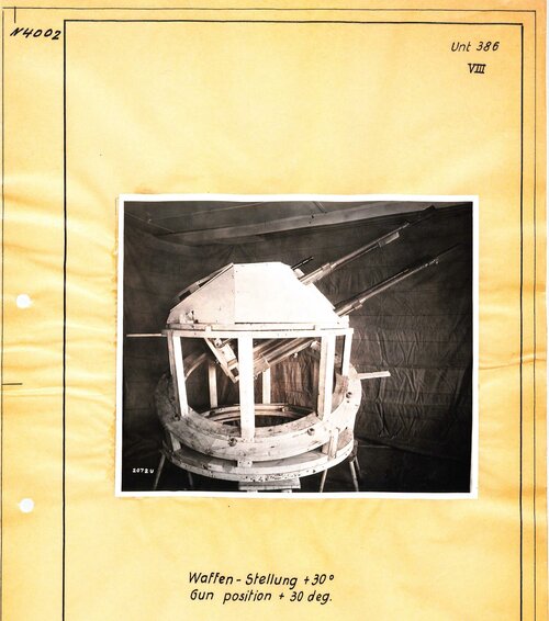
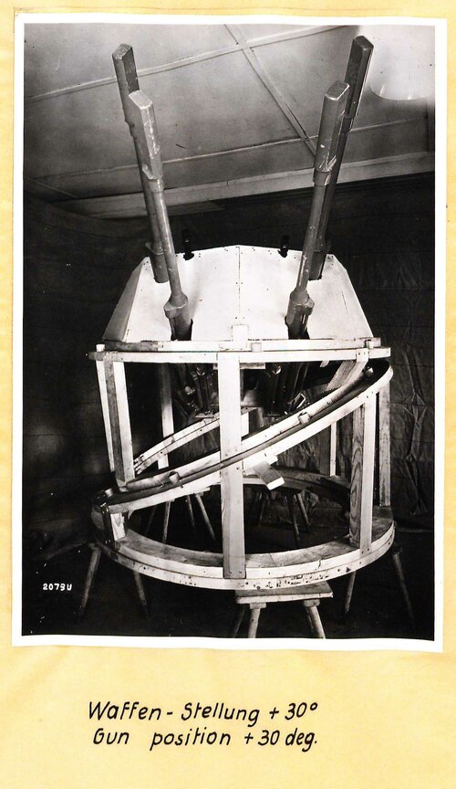
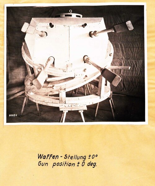
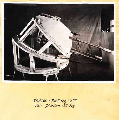
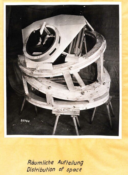
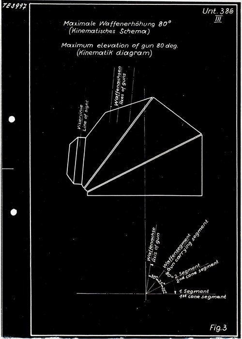
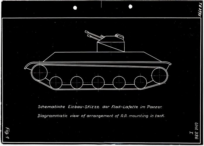
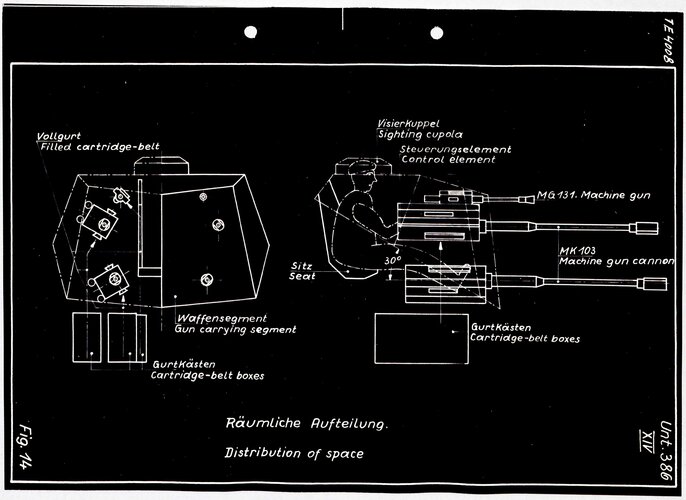
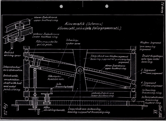
This, the last Flakpanzer designed by Rheinmetall-Borsig from late 1944, was incited by the SS-Führungshauptamt and fathered by SS-Hauptsturmführer Wabnitz. It proceeded to the last days of WW2, and not just a wooden mockup was made since metal was cut. All the plans were destroyed in a air raid. Mind that, apart from the four MK 103, there were two MG 131. There were cylinder segments (kalotte, much like the "Kugelbliz" turret), one sporting the fixed armament, oscillating via roller bearings. The traversing ring`s diameter amounted to 1470mm, much smaller than the Kugelblitz. There was a hydraulic handlebar control, developed by Dr. Himmler from D.V.L. (I believe it to be the same intended to the Kugelblitz), the aiming device shown (telescope with 0 magnification, 60º filed of view) is a stopgap before a more advanced one was installed. The report`s author mentions that he couldn`t collect more data from the fire control experts, who were absent after the war was over, but remoete and director control was meant in a latter stage of development. Also the stabilisation of the turret was discussed, but the late-war situation prevented further advances. Report found at the IWM.
Dear Moderators, this thread should be at "Army Secret Projects". Sorry for any inconvenience.
 

Attachments

  • Torre 1.jpg
    Torre 1.jpg
    298.9 KB · Views: 95
  • Torre 3.jpg
    Torre 3.jpg
    669.2 KB · Views: 81
  • Torre 4.jpg
    Torre 4.jpg
    334.3 KB · Views: 78
  • Torre 5.jpg
    Torre 5.jpg
    331.7 KB · Views: 80
  • Torre 6.jpg
    Torre 6.jpg
    358.1 KB · Views: 80
  • torre 7.jpg
    torre 7.jpg
    290.5 KB · Views: 77
  • Torre 2.jpg
    Torre 2.jpg
    433.1 KB · Views: 93
  • Torre 8.jpg
    Torre 8.jpg
    448.4 KB · Views: 92
  • Torre 9.jpg
    Torre 9.jpg
    512.8 KB · Views: 103
One snag seems to be that you can't mount anything to the inside of the turret sections, because they'll be moving relative to each other and the crew whenever the guns are elevated or depressed?

Delivering hydraulic power to the second and third tier seems likely to have been a challenge too
 
One snag seems to be that you can't mount anything to the inside of the turret sections, because they'll be moving relative to each other and the crew whenever the guns are elevated or depressed?

Delivering hydraulic power to the second and third tier seems likely to have been a challenge too
I`m sure R-B engineers would know better than you and me when designing and cutting metal to it. I`m attaching another drawing, not the report`s explanations on the three toothed rings ring on the different revolving segments.
 

Attachments

  • Torre 10.png
    Torre 10.png
    5.9 MB · Views: 88
I`m sure R-B engineers would know better than you and me when designing and cutting metal to it. I`m attaching another drawing, not the report`s explanations on the three toothed rings ring on the different revolving segments.

While that does explain how they intended to drive the sections, I've just thrown a rough model into Fusion360 and there's an issue with the kinematics - as you elevate and depress the gun, there's a sinusoidal oscillation of roughly 5 degrees in traverse with zeros at max elevation, max depression and halfway between.

I'm sure it could be compensated for manually using the separate traverse and elevation controls shown, but I'm not sure it would be great for accuracy.

Also, the upper barrel would need to turn at twice the rate of the lower barrel (and in the opposite direction), so there would need to be a 2:1 gear ratio in the drive transfer gears (the schematic illustration appears to show a roughly 1:1 ratio, presumably for ease of drawing)


EDIT:
After thinking about the mechanics more, I realised my rough model was too rough - I only modelled the outer barrel sections, not the internal mechanism.

As a result, all the issues I found would be resolved by adding the internal mechanism - the internal pedestal mount prevents the guns from unwanted traversing, and also ensures that the two barrel halves rotate correctly.

Never try to do mechanical analysis while tired
 
Last edited:
Hi Wurger,

I`m sure R-B engineers would know better than you and me when designing and cutting metal to it. I`m attaching another drawing, not the report`s explanations on the three toothed rings ring on the different revolving segments.

Thanks, that's quite interesting.

So the two segments can't rotate independently, and the "magic" is performed by the telescoping shaft! :) Not as complex as I'd have thought.

Regards,

Henning (HoHun)
 
A brilliant find, any thoughts as to intended hull & chassis (I'm assuming the elevation drawing is notional ?)
The narrow turret ring puts it between the Panzer 38(t) and the Panzer III. I will not speculate on the chassis without a solid base. The sketch is, most probably, just notional.
 

Similar threads

Please donate to support the forum.

Back
Top Bottom