- Joined
- 1 April 2006
- Messages
- 11,375
- Reaction score
- 10,209
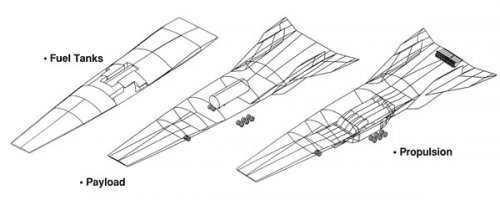
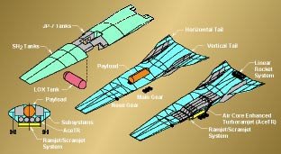
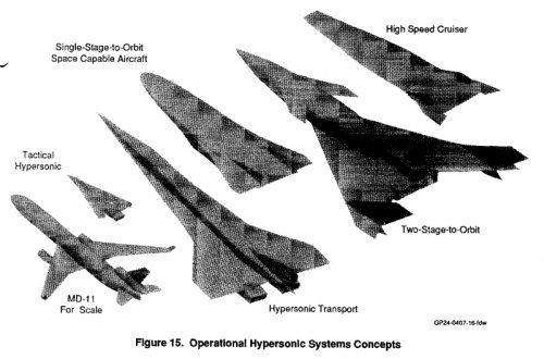
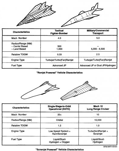
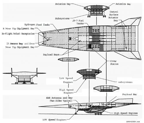
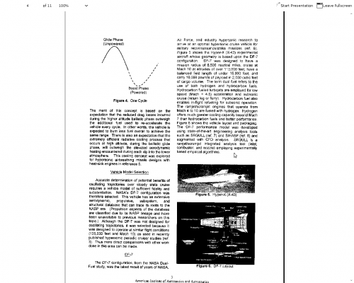
Excerpt and drawings from some Boeing AIAA papers. DF stays for Dual Fuel
______________________________________________
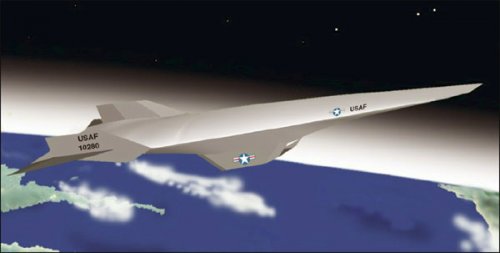
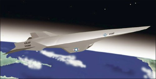
The Mach 10 aircraft concept which became
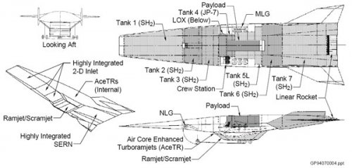
the vision for Hyper-X, features a lifting body configuration with an over-andunder
turbine based combination cycle (TBCC) engine
system. For this system, four hydrocarbon-fueled, lowspeed
turbo-ramjet engines are integrated inside the
vehicle, directly above three high-speed, hydrogenfueled
scramjet engines. This 61 m-long aircraft was
sized for an operating radius of 8500 nautical miles
(nm). The low-speed engines are used initially for takeoff
and acceleration to Mach 4. The high-speed engines
are then used for acceleration to and cruise at Mach 10.
Following the high-speed cruise mission, the aircraft
returns to base sub-sonically using the low-speed
engines. During return, it is refueled using KC-10
tanker aircraft. (!) (All of the engine design and
performance information, employed in the definition of
this Mach 10 aircraft, was provided by Pratt &
Whitney.)
The airframe structure, materials, thermal protection
system (TPS), vehicle management system, and
subsystems for the Mach 10 aircraft are described in
References 2,3 and 4. The fuselage is based on a cold,
integral structure, in which the cryogenic hydrogen
tanks are integral with the airframe. The tanks/fuselage
are built-up with graphite-epoxy frames and skins, and
the skins are covered with TPS. The TPS consists of
Tailorable Advanced Blanket Insulation (TABI) on the
upper surface of the aircraft (similar to the Shuttle
Orbiter) and Internal Multi-Screen Insulation (IMI) on
the lower surface. IMI is a developmental TPS, which
consists of carbon/silicon-carbide (C/SIC) outer panels,
intermediate ceramic screens, separated by ceramic
spacers, and an internal layer of advanced polyimide
foam (APF). The intermediate ceramic screens are
coated with a noble metal to reduce their emissivity.
The wings and vertical tails are constructed of titanium
matrix composite material and have zirconium diboride
leading edges. The nose consists of a hydrogen-cooled
NARloy-Z structure.
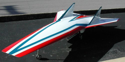
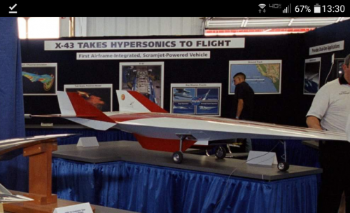
With this aircraft concept serving as a vision vehicle,
the Hyper-X (X-43A) was conceived to demonstrate, in
flight, the performance of an airframe-integrated,
scramjet powered vehicle. Also, Hyper-X II (which
later evolved into the X-43B) was conceived as a
follow-on step to demonstrate a larger, more flightweight,
scramjet powered aircraft. These flight
research vehicles became part of NASA’s Advanced
Space Transportation Program (ASTP), and a third
vehicle, the X-43C, was added to serve as an
intermediate step between the X-43A and X-43B. In
addition, a large-scale flight demonstration vehicle is
being considered as part of the ASTP hypersonics
investment strategy. This vehicle could lead to a future
hypersonic aircraft or 3rd generation, air-breathing,
reusable launch vehicle.

