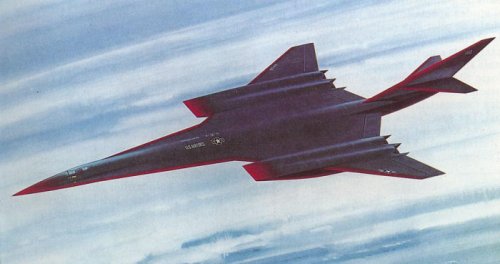
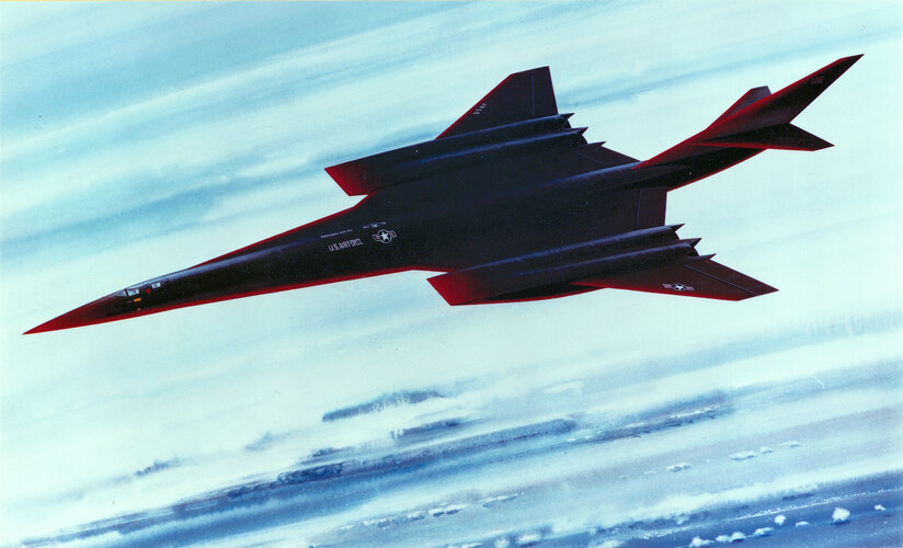
Lockheed ADP/NASA Langley 1990 Mach 4 - Mach 5 methane fueled aircraft studies

flateric

ACCESS: USAP
Staff member
Top Contributor
Senior Member
Joined
1 April 2006
Messages
11,121
Reaction score
8,803
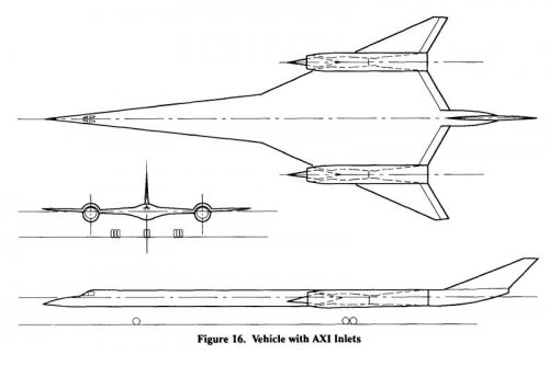
AlAA 90-2151
Airframe/Propulsion Integration of Supersonic Cruise Vehicles
J. Anderson
Lockheed Advanced Development Projects
Burbank, CA

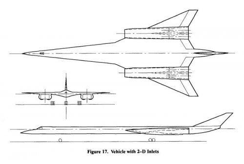
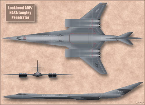
"...A system performance study was conducted by the Lockheed Advanced Development Projects (ADP) organization under a subcontract to Pratt & Whitney in support of the Air Force Enhanced Flow Compressor contract. This study investigated the system performance, impacts of the inlet/lengine match and the implications of engine flow scheduling vs Mach number.
The baseline aircraft used in the study was a derivative of the Mach 5 methane fueled cruise vehicle developed in a joint effort between ADP and NASA Langley - (pics 3 and 4 - Flateric). The derivative aircraft was a Mach 4, JP fueled aircraft. Both aircraft were designed for long range cruise at their respective design Mach numbers. The baseline aircraft was configured with propulsion
nacelles located on the wings. For this study, these nacelles were removed from the aircraft design and replaced with the various new inletlengine combinations being studied."
 

Attachments

  • ADP-1990-SCV-1.jpg
    ADP-1990-SCV-1.jpg
    31.4 KB · Views: 986
  • ADP-1990-SCV-2.jpg
    ADP-1990-SCV-2.jpg
    32.5 KB · Views: 878
  • Lockheed 89 EF M4-5 penetrator-1.JPG
    Lockheed 89 EF M4-5 penetrator-1.JPG
    42.4 KB · Views: 877
  • Lockheed 89 EF M4-5 penetrator-2.JPG
    Lockheed 89 EF M4-5 penetrator-2.JPG
    72.9 KB · Views: 860

Attachments

  • Mach5Colored2.png
    Mach5Colored2.png
    650.6 KB · Views: 471
Hi,

here is the Lockheed hypersonic,they called
it Mach 7.

http://books.google.com.eg/books?id=y-QDAAAAMBAJ&pg=PA71&dq=Mach+5+aircraft&hl=ar&ei=dTxATPHYFMuK4QaB8q2nDg&sa=X&oi=book_result&ct=result&resnum=16&ved=0CHMQ6AEwDw#v=onepage&q=Mach%205%20aircraft&f=true
 

Attachments

  • 1.JPG
    1.JPG
    19.6 KB · Views: 666
I think it was just listing the speed of the different vehicles, and this one got the 'Mach 7' label. Some of them also look a bit fanciful, like the Akula (I think) submarine's long tail and the weird hydroplane boat. Others like Thrust 2 look nearly dead-on. I was also wondering about the glowing leading edges on Mr. Lockheed Mach 7 in light of the mountains in the background implying he's flying in the dense lower atmosphere. I think an object going M7 at STP would give off intense blue-white or even violet-white light just like an arc welder.

Bravissimo for finding a view of Mr Lockheed's belly. That ranks up there with the various FDL and waverider hypersonics as my favorite unbuilt designs.
 
Excuse my ignorance, but why methane? I know it has been looked at for powering more conventional aircraft as well as rockets, but what makes it applicable to a Mach 4+ design?
 
Colonial-Marine said:
Excuse my ignorance, but why methane? I know it has been looked at for powering more conventional aircraft as well as rockets, but what makes it applicable to a Mach 4+ design?

1) It's cold. Useful for cooling an aircraft at those speeds.
2) It combusts faster than regualr jet fuel (important when dealing with speeds that put air through engines in *milliseconds*
3) It has more energy per unit mass than regular jet fuel.
4) It's denser than hydrogen.
5) It can be manufactured easily, unlike jet fuel.
6) There's lots of it underground.

Main negative of methane is that it's substantially less dense than regualr jet fuel, and is more difficult to handle.
 
Orionblamblam said:
Main negative of methane is that it's substantially less dense than regualr jet fuel, and is more difficult to handle.


Another not so nice property is it's tendency to detonate more easily than say H2.
 
dannydale said:
Hay guise! I found something that looks suspiciously like an engine nacelle from this beast!
...

Yes, there are a fair number of papers on this study whose titles are unclassified, but the body
of the paper is still secret.

There are also a few papers that are actually published and available via AIAA.

If you want to get excited and then frustrated:
http://www.secretprojects.co.uk/forum/index.php/topic,10338.msg97434.html#msg97434

Regards.
 
By the way.

The ISABE paper that can be found via the previous link is available via the
ISABE proceedings.

I have a copy. Interesting paper!

The 2-D inlet did not perform as well. A vortex instability on the sidewall from what I
recall. But the axisymmetric inlet did better (see flateric's 2 pix at the start of this
thread).

Also, the design called for the ramjet to cold-flow until it was needed.
I found this very interesting.
 
dannydale said:
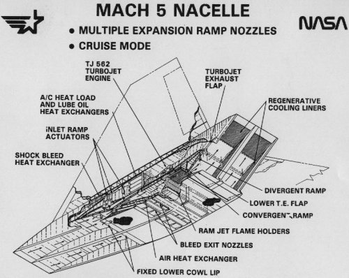
Hay guise! I found something that looks suspiciously like an engine nacelle from this beast!

http://crgis.ndc.nasa.gov/historic/File:1982_Mach_5_Nacelle_Multiple_Expansion_Ramp_Nozzles.jpg

I previously missed this: nice find - I'm sure there is a .pdf on DTIC or NTRS covering Wind Tunnel testing of (what seemed very likely to have been) this Inlet (but it may not have been specifically identified as such)....
 
With the ever increasing push of methane in rocketry...Lockmart might want to revisit this concept. Now I wonder if a tripropellant approach might yield a spaceplane at last...methalox rocket for an upper stage...perhaps with ammonia-to-hydrogen tech mixed in for a Star Raker type first stage?
 
AlAA 90-2151
Airframe/Propulsion Integration of Supersonic Cruise Vehicles
J. Anderson
Lockheed Advanced Development Projects
Burbank, CA

"...A system performance study was conducted by the Lockheed Advanced Development Projects (ADP) organization under a subcontract to Pratt & Whitney in support of the Air Force Enhanced Flow Compressor contract. This study investigated the system performance, impacts of the inlet/lengine match and the implications of engine flow scheduling vs Mach number.
The baseline aircraft used in the study was a derivative of the Mach 5 methane fueled cruise vehicle developed in a joint effort between ADP and NASA Langley - (pics 3 and 4 - Flateric). The derivative aircraft was a Mach 4, JP fueled aircraft. Both aircraft were designed for long range cruise at their respective design Mach numbers. The baseline aircraft was configured with propulsion
nacelles located on the wings. For this study, these nacelles were removed from the aircraft design and replaced with the various new inletlengine combinations being studied."
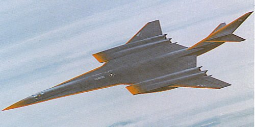
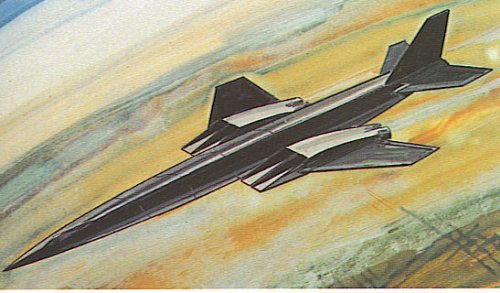
The artist's renderings predate the 1990 system performance study by Lockheed and NASA Langley, and since they appear on pages 51 and 91 of the book An Illustrated Guide to Future Fighters and Combat Aircraft (published in 1984), the aircraft designs in these artist's rendering were apparently conceived in 1982-1984 judging from the fact that a Lockheed company cutaway view of the turboramjet for the Mach 5 Lockheed design powered by methane-burning variable cycle turboramjets (see reply #8 above) is dated 1982.
 
The artist's renderings predate the 1990 system performance study by Lockheed and NASA Langley, and since they appear on pages 51 and 91 of the book An Illustrated Guide to Future Fighters and Combat Aircraft (published in 1984), the aircraft designs in these artist's rendering were apparently conceived in 1982-1984 judging from the fact that a Lockheed company cutaway view of the turboramjet for the Mach 5 Lockheed design powered by methane-burning variable cycle turboramjets (see reply #8 above) is dated 1982.
from HIGH-SPEED INLET RESEARCH PROGRAM AND SUPPORTING ANALYSES

MACH 5 CRUISE AIRCRAFT STUDY
In 1980, a joint NASA Lewis, NASA Langley, and Lockheed California (with P&W as subcontractor) program was initiated. The purpose of this study was to define an aircraft capable of sustained high-speed cruise, and specifically, to define the propulsion system for this aircraft. The final configuration from this study is shown in the figure. The aircraft would employ four propulsion modules (two under each wing). The propulsion system chosen for this aircraft is an over-under turbojet plus ramjet system with a two-dimensional dual flow inlet and nozzle.​
 
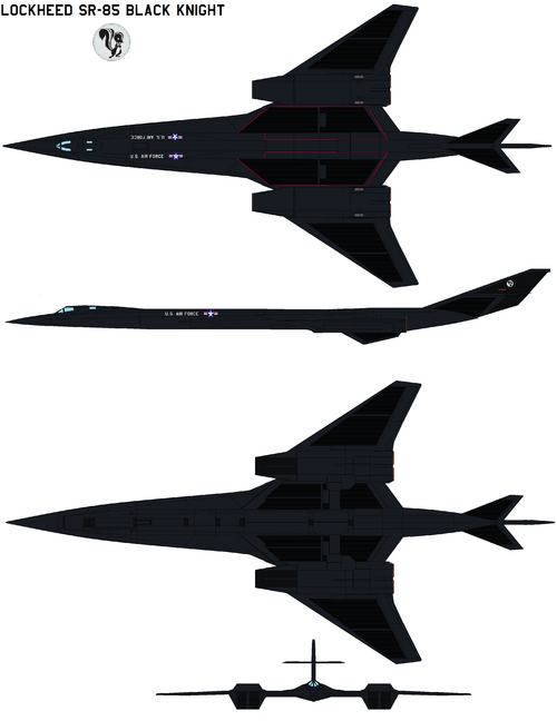
I'm wanting to get a 3D model of this aircraft made (and ultimately a 3D-printed model), but the tail configuration is confusing me. It doesn't look like there is a rudder on the vertical tail. Is it possible that it is all-moving? Given that it is a cruciform tail, then an all-moving vertical tail would carry around the horizontal tails with it. That sounds like it might be a problem for horizontal tail effectiveness. Has such a configuration ever been tried before? Or should I just assume that the artist's impression is incomplete and that a real aircraft would have a rudder?
 
Is that a very slim trim rudder at the rear of the fin on the artwork (might be a screen artifact?) possibly all moving tailplanes tho
 
I wonder if it would be possible to gimbal the whole tail---using hydraulics. At those speeds..you need something with authority
 
Back
Top Bottom